<> <>
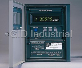
Model DM8
General
Vibration Type Liquid Density Meter
Specifications
GS 12T3A1-E
nOverview
In 1967, YOKOGAWA developed the Model VD6
Vibration Type Liquid Density Meter in response to user
requests for an online density meter, to assist in process
automation and saving labor resources and energy while
further improving and stabilizing quality. This was an
important development in the instrumentation field,
because density is a fundamental physical quantity, the
accurate measurement of which is important for almost all
processes. The VD6 density meter has gone on to
develop an excellent reputation as a highly stable high
sensitivity meter.
The Model DM8 Vibration Type Density Meter is a highly
reliable, multi-function meter developed on the basis of
our experience with the VD6 and which takes advanrage
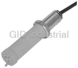
Converter Detector
of the latest computer technology to integrate a wide
range of sensor techniques. Its converter incorporates a
microprocessor to directly convert frequency signals from
the sensor into density values and display them and is
provided with a variety of functions such as one-touch
calibration, self diagnosis, digital output (RS-232C), etc.
Measuring liquid temperature: –10 to 100 °CnSystem Configuration
Measuring liquid pressure: 2 MPa G or less
Withstandable pressure: 4.9 MPa G
Model VD6SM
Steam tracing: Available
Sampling unit
Process connection: Rc1/4
Electrical connection: G3/4
Model DM8W
Mounting: JIS 50A pipe mounting
Model VD6D
Special cable
Model DM8C Transmission
Ambient temperature: –10 to 50 °C
Model VD6DF Detector
Max. 2 km Converter signal
Weight: Approx. 12 kg
Model VD6DS
(2) Flameproof (Explosionproof) Detector Model
VD6DF
nStandard Specifications
Detector construction: TIIS d2G3 or NEC Class I, Division
1, Groups C and D, Flameproof construction
1. General Specifications
Process connection: Rc1/4 or 1/4NPT female (only for
Measurement object: Liquid density
VD6DF-uu*B/FM)
Measurement principle: Vibration density measurement
Electrical connection: G3/4 or 3/4NPSM female (only for
Measurement range:
3 VD6DF-uu*B/FM)
Density: 0.5 to 2.0 g/cm
Specifications are the same as for the (1) General
Temperature: –10 to 100 °C
Purpose Detector except for the above construction.
Distance between Detector and Converter: Up to 2 km
Power supply: 90 to 132 V AC or 180 to 264 V AC,
(3) Sanitary Use Detector Model VD6DS
50/60 Hz
Process connection: Special joint for connection to
Power consumption:20 VA
JIS 6A pipe (with gasket)
Wetted part materials: Added to the standard model
2. Detector
Gasket: Teflon
(1) General Purpose Detector Model VD6D
O-Ring: Viton
Detector construction: Non-explosion protection, rain-
Stream tracing: Not available
proof construction
Specifications are the same as for the (1) General
Case material: Cast Aluminium alloy
Purpose Detector except for the above two items.
Case coating: Epoxy rasin, baked finish
Temperature detector protecting tubes are detachable.
Case color: Jade green (equivalent to Munsell 7.5BG4/
1.5)
These detectors cannot be used with highly corrosive
Wetted part materials:
liquids and solutions likely to stick to sensors. If it is desired
Base: SUS316
to be applied to solutions containing slurry or sludge,
Vibrator: SUS316 or Ni (Au Blazing: BAu·4)
consult with YOKOGAWA. For measuring NaOH solutions,
use sensors with a nickel vibrator.
Yokogawa Electric Corporation GS 12T3A1-E
2-9-32, Nakacho, Musashino-shi, Tokyo, 180-8750 Japan ©Copyright Apr. 1998
Tel.: 81-422-52-5617 Fax.: 81-422-52-6792 7th Edition Apr. 2009
2
<> <>
Mounting: To panel, wall or JIS 50A pipe
3. Converter Model DM8C
Air purge connector: Rc1/8, Rc1/4, or 1/4NPT female is
Display: Digital display, five digits LED
also optionally available
Display contents:
3
Electrical connection: Five holes, 27 mm dia.
Density (g/cm ) after conversion to reference
Attached with four plastic waterproof plugs
temperature (center temperature)
3
equivalent to JIS A15, and one plastic
Density (g/cm ) at the measuring temperature
waterproof plug equivalent to JIS A20.
Measuring liquid temperature (°C)
3
Weight: Approx. 7.5 kg
Set density value for the calibration liquid (g/cm )
(displayed on call)
4. Special Cable Model DM8W
Temperature coefficient set value for the calibration
Type: Six-conductor double shield cable
–5 3
liquid (310 g/cm /°C) (displayed on
Insulator: Polyethylene
call)
Sheath: Polyvinyl chloride
Output signal set value (%) (displayed on call)
Insulation resistance: 1000 MV/km
3
Setting for output range low limit (g/cm ) (displayed
Conductor resistance: 15.31 V/km
on call)
Finished O.D.: 15.8 mm
3
Setting for output range high limit (g/cm ) (displayed
5. Sampling Unit Model VD6SM
on call)
External dimensions: Approx. 400(W) 3 400(D) 3
Reference temperature (center temperature) set
1350(H) mm
value (°C) (displayed on call)
Coating finish: Epoxy resin, baked gray finish (equivalent
Temperature coefficient set value for the measuring
–5 3 to Munsell N7)
liquid (310 g/cm /°C) (displayed on
Watted part materials: SUS316, Teflon (gasket for
call)
flowmeter, pressure gauge and strainer), Ni
Fault contents display
for /FN option.
Output signal:
Weight: Approx. 80 kg
Analog output:
Process conditons:
4 to 20 mA DC (load resistance 550 V or less), and
Inlet temperature: 0 to 100 °C
0 to 1 V DC (load resistance 250 kV or
Inlet pressure: 0 to 1 MPa or 0 to 2 MPa
more), isolated output.
3 Required differential pressure: At least 100 kPa
Density (g/cm ) after conversion to the reference
Flow rate: 1 to 10 l/min
temperature
Digital ooutput:
FM
TI PI
To RS-232C
BV1 NV4
DD
3
Density (g/cm ) after conversion to the reference
Inlet
temperature
F
3
NV1 NV2 NV3
Density (g/cm ) at the measured temperature
Measured liquid temperature
Calibration state
Outlet
Failure alarm
3 Sampling System Diagram
Output signal span: 0.05 to 0.5 g/cm settable
Reference temperature set range: 0 to 100 °C (in
Element specitications
increments or decrements of 1 °C)
F: Strainer body; SUS316,
Contact output on failure: One point. Contact closed on
element; SUS316, Ni fo /FN option
failure or power failure. Contact open when PI: Pressure gauge, 0 to 1 MPa or 0 to 2 MPa, SUS316
TI: Thermometer, 0 to 100 °C or 0 to 150 °C, SUS316
normal.
FM: Flowmeter, tapered metal tube flowmeter, 1 to 10 l/
Permissible voltage: 220 V DC, 250 V AC
min, SUS316
Permissible current: 2A (resistive load)
BV: Ball valve, SUS316
Permissible contact power: 60 W
NV: Needle valve, SUS316
Fault detecting contents: Detector failure and converter
DD: Density detector
failure
Note: This sampling system cannot normally be
Failure output:
applied to food applications, if it is desired to
Analog signal: Falls down to about –10 % of the output
be applied to food applications, consult with
signal span
YOKOGAWA.
Digital signal: Error message outputs
Output signal hold: Holds in the CAL. or Maintenance
nCharacteristics
mode.
(overall characteristics after combing the detector and the
Settable range for temperature coefficient: 0 to 0.002 g/
3 converter)
cm /°C
–4 3
Calibration procedure: One-touch calibration by strong Repeatability: 5 3 10 g/cm (for digital output)
calibration liquid density (one-point 1 % of span (for analog output)
3
Linearity: ±0.5 % of span (when span is 0.2 g/cm or
calibration)
Ambient temperature: –10 to 55 °C less)
Power supply: 90 to 132 V AC or 180 to 264 V AC, ±1 % of span (when span is more than 0.2 g/
3
cm )
50/60 Hz
Case construction: Dust and rain proof construction Temperature characteristics: ±0.5 % of span/±10 °C
Coating color: (Compensating error for changes in the
measuring liquid temperature and detector
Door: Equivalent to Munsell 2.8GY6.4/0.9
Case: Equivalent to Munsell 2.0GY3.1/0.5 temperature)
Coating finish: Baked finish epoxy resin
All Rights Reserved. Copyright © 1988, Yokogawa Electric Corporation GS 12T3A1-E 7th Edition Apr.09,2009-00
3
<> <>
Flow characteristics:±0.1 % of span in the 0 to 5 l/min
range
3
Pressure characteristics: ±0.0005 g/cm /±98 kPa change
Viscosity error: ±0.1 % of span in the 0 to 1500 cP range
nStandard Accessories
Syringe (for injecting standard 1 pc.
(3) Sanitary Use Detector
solution or solvenet)
Brush (for cleaning the detector) 1 pc.
Model Suffix code Option code Description
Allen wrench for terminal box 1 pc. for Detector (VD6)
VD6DS Sanitary use detector
Allen wrench for locking the cover 1 pc.
Vibrator -S3 SUS316
O-Ring 1 bag
material
Silica gel 2 packs
B Style B
*
Fuse for the converter (3A) 1 pc. for Converter (DM8C)
2. Converter
nModel and Suffix Codes
Model Suffix code Option code Description
DM8C Converter
1 . Detector
Power -A1 90 to 132V AC, 50/60Hz
(1) General Purpose Detector
supply -A2 180 to 264V AC, 50/60Hz
C Style C
Model Suffix code Option code Description
*
(Option) /AP1 Rc1/4
VD6D General purpose detector
Air purge connector /AP2 1/4NPT female
Vibrator -S3 SUS316
material -N1 Ni
B Style B
*
3. Special Cable
(2) Flameproof Detector
Model Suffix code Option code Description
DM8W Special cable
Model Suffix code Option code Description
Cable length -Lhhhh Length (unit: m)
VD6DF Flameproof detector
A Style A
*
Vibrator -S3 SUS316
material -N1 Ni
(Note) Enter the cable length in “-Lhhhh in m.”
B Style B
[Example] L0050 for 50 m
*
(Option) /FM NEC Class I,Division 1,Group
L0100 for 100 m
C and D, explosionproof
L2000 for 2 km
4. Sampling Unit
Option
Description
Model Suffix code
code
Sampling unit for Vibration type Density Meter (Note 1)
VD6SM
-JPT Rc1/2
-10K JIS 10K 15 RF Flange
-20K JIS 20K 15 RF Flange
Piping -150 ANSI Class 150 1/2 RF Flange
connection
-300 ANSI Class 300 1/2 RF Flange
-151 JPI Class 150 1/2 RF Flange
-301 JPI Class 300 1/2 RF Flange
-WST 1/2 inch welding socket
-PG10
1 MPa
Pressure
-PG20
2 MPa
guage
-PK10
Diaphragm type 1 MPa
range
-PK20
Diaphragm type 2 MPa
-T100 0 to 1008C
Temperature
range -T150 0 to 1508C
B Style B
Style code
*
Option
With steam tracing (Note 2)
/ST
Ni (Note 3)
Material of strainer element
/FN
(Note 1) VD6SM Sampling unit is not including Detector. Order detector VD6D or VD6DF, separately.
DM8C converter and special cable DM8W are also required for sampling system of density meter.
(Note 2) If stean tracing is necessary, select the diaphragm type pressure guage.
(Note 3) If measuring solution includes NaOH (%30%) , select option code /FN of Ni.
All Rights Reserved. Copyright © 1988, Yokogawa Electric Corporation GS 12T3A1-E 7th Edition Apr.09,2009-00
4
<> <>
nWiring Connection
Detector Special cable Converter
RED
Closed when a failure
A2 A2 N.C
Alarm is detected or the
BLUE
A3 A3 C power fails.
YELLOW
• Density signal after being
A4 A4
SG
converted to the reference
BROWN
A6 A6
temperature state
Digital signal
RD
• Density signal before
GREEN
A5 A5
being converted to the
TD
WHITE reference temperature state
B4 B4
• Temperature signal
GRAY +
B5 B5
0 to 1V DC
-
Density signal after being
converted to the reference
+
temperature state
4 to 20mA DC
-
G
L1 L2
Power supply
nExternal Dimensions
1. Detector
lGeneral Purpose and Flameproof Detector Models VD6D and VD6DF
246
Unit: mm
100
192
Steam Connection Rc1/4
Sample lnlet Rc1/4
(1/4NPT for VD6DF-uu*B/FM)
[116
(1/4NPT for
Sample Outlet Rc1/4 [74
VD6DF-uu*B/FM)
(1/4NPT for VD6DF-uu*B/FM)
50A (2-inch) Pipe
(Horizontal or Vertical)
Electrical Wiring Port G3/4
(3/4NPSM for
VD6DF-uu*B/FM)
[160
146
All Rights Reserved. Copyright © 1988, Yokogawa Electric Corporation GS 12T3A1-E 7th Edition Apr.09,2009-00
200 342
100
78
[110
58 104
153
5
<> <>
lSanitary Use Detector Model VD6DS
246
Unit: mm
100
192
Gland
166
[116
Sample lnlet *
Sample Output * [74
50A (2-inch) Pipe
(Horizontal or Vertical)
Electrical Wiring Port
G3/4
[160
146
* The ends of sample inlet and outlet are connected with 6A (1/8-inch)
pipe in welding. The pipe may be removed by loosing the gland.
All Rights Reserved. Copyright © 1988, Yokogawa Electric Corporation GS 12T3A1-E 7th Edition Apr.09,2009-00
200 345
103
73
[110
58 104
153
6
<> <>
2. Converter Model DM8C
Unit: mm
Mounting bracket (applicable with any mounting
Wiring port holes (5-ø27)
method to panels, walls or pipes)
(with rubber plugs)
Mounting panel thickness
Max. 12
Purge air inlet Rc1/8
Pipe mounting bracket
Purge air outlet
(with seal sheet)
Mounting pipe
(50A (2-inch) pipe)
3. Special Cable Model DM8W
Density detector Density converter Unit: mm
130(from A)
(from B)100
B4 B4
WHITE
60(from A) (from B)
WHITE
80
B5 B5
GRAY
A B
GRAY
(from B)
50m, 100m, or 2km
110(from A)
120
A2
A2
RED
RED
A3
A3
(from B) BLUE
110(from A)
BLUE
110
A4
A4
60 YELLOW
YELLOW
(from B)100
[15.8
(from A)
A5 A5
GREEN
110(from A)
GREEN (from B)90
A6 A6
BROWN
60(from A) (from B)80
BROWN
All Rights Reserved. Copyright © 1988, Yokogawa Electric Corporation GS 12T3A1-E 7th Edition Apr.09,2009-00
7
<> <>
4. Sampling Unit Model VD6SM
Unit: mm
Steam Trap
270
400
Note: Some detail of steam trace
50 tube omitted in this drawings.
4 - [15
(*1): Only for with steam trace.(option /ST)
50
holes 300
P - P view
(Steam trace only) (*1)
400
For Anchor
Bolts
Pressure
Gauge
Thermometer
Detector
1350
Condensate
Outlet(*1)
125 150
Flowmeter
Steam
P
P
Sample
(*1)
Inlet
Outlet
Sample
Inlet
strainer 150
200
34
(100)
Approx.407 L 100 200
L
(for flange) (for welding
socket)
L
Model and Codes Connection Type
VD6SM - JPT - Puu 0 - T1 u 0 pB Rc 1/2 female 0
VD6SM - 10K - Puu 0 - T1 u 0 pB JIS 10K 15 RF Flange 100
VD6SM - 20K - Puu 0 - T1 u 0 pB JIS 20K 15 RF Flange 100
VD6SM - 150 - Puu 0 - T1 u 0 pB ANSI Class 150 1/2 RF Flange 100
VD6SM - 300 - Puu 0 - T1 u 0 pB ANSI Class 300 1/2 RF Flange 100
VD6SM - 151 - Puu 0 - T1 u 0 pB JPI Class 150 1/2 RF Flange 100
VD6SM - 301 - Puu 0 - T1 u 0 pB JPI Class 300 1/2 RF Flange 100
VD6SM - WST - Puu 0 - T1 u 0 pB 1/2 B Welding Socket 100
All Rights Reserved. Copyright © 1988, Yokogawa Electric Corporation GS 12T3A1-E 7th Edition Apr.09,2009-00
8
<> <>
Inquireis sheet for the Vibration Liquid Density Meter
Thank you for inqurity on our vibrationliquid density meter.
Please specify your requiremets by checking the appropriate boxes and filling in the blanks with the requested information.
1. General Items
Company name:
Contact person: Section:
Address: (Phone No. )
Plant name:
Measurement location:
Purpose: u Indication u Recording u Alarm u Control
2. Measurement conditions
(1) Liquid temperature: to , normally [°C]
(2) Liquid pressure: to , normally [kPa]
(3) Liquid flowrate: to , normally [l/min]
(4) Slurry or soiling components?: u Yes u No
(5) Name of measured liquid:
(6) Composition of measured liquid:
(7) Other:
3. Installation location
(1) Ambient temperature:
(2) Installation location: u Outdoors u Indoors
(3) Other:
4. User requirements
(1) Measurement range:
(2) Vibration material: u SUS316 u Ni
(3) Cable length between detector and converter: m
(4) Power supply: u 90 to 132 V AC u 180 to 264 V AC
(5) Other:
All Rights Reserved. Copyright © 1988, Yokogawa Electric Corporation GS 12T3A1-E 7th Edition Apr.09,2009-00


 Manufacturers


What they say about us
FANTASTIC RESOURCE
One of our top priorities is maintaining our business with precision, and we are constantly looking for affiliates that can help us achieve our goal. With the aid of GID Industrial, our obsolete product management has never been more efficient. They have been a great resource to our company, and have quickly become a go-to supplier on our list!
Bucher Emhart Glass
EXCELLENT SERVICE
With our strict fundamentals and high expectations, we were surprised when we came across GID Industrial and their competitive pricing. When we approached them with our issue, they were incredibly confident in being able to provide us with a seamless solution at the best price for us. GID Industrial quickly understood our needs and provided us with excellent service, as well as fully tested product to ensure what we received would be the right fit for our company.
Fuji
HARD TO FIND A BETTER PROVIDER
Our company provides services to aid in the manufacture of technological products, such as semiconductors and flat panel displays, and often searching for distributors of obsolete product we require can waste time and money. Finding GID Industrial proved to be a great asset to our company, with cost effective solutions and superior knowledge on all of their materials, it’d be hard to find a better provider of obsolete or hard to find products.
Applied Materials
CONSISTENTLY DELIVERS QUALITY SOLUTIONS
Over the years, the equipment used in our company becomes discontinued, but they’re still of great use to us and our customers. Once these products are no longer available through the manufacturer, finding a reliable, quick supplier is a necessity, and luckily for us, GID Industrial has provided the most trustworthy, quality solutions to our obsolete component needs.
Nidec Vamco
TERRIFIC RESOURCE
This company has been a terrific help to us (I work for Trican Well Service) in sourcing the Micron Ram Memory we needed for our Siemens computers. Great service! And great pricing! I know when the product is shipping and when it will arrive, all the way through the ordering process.
Trican Well Service
GO TO SOURCE
When I can't find an obsolete part, I first call GID and they'll come up with my parts every time. Great customer service and follow up as well. Scott emails me from time to time to touch base and see if we're having trouble finding something.....which is often with our 25 yr old equipment.
ConAgra Foods