

 Manufacturers
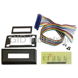
RED LION CONTROLS MDMU0110
Description
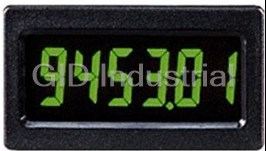
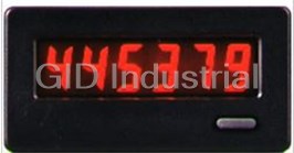
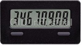
Red Lion Controls MDMU0110MINIATURE DISPLAY MODULE COUNTER/TIMER 6-DIG YEL BKLIT PCB MNT 4.5 V ~ 5.5 V LCD Backlit
Part Number
MDMU0110
Price
Request Quote
Manufacturer
RED LION CONTROLS
Lead Time
Request Quote
Category
TIMERS, COUNTER & METERS
Features
- 5 VDC POWERED
- 9 RANGES IN TIMER MODE
- COUNT POSITIVE OR NEGATIVE EDGE
- COUNTER & TIMER ALL IN A SINGLE UNIT
- LCD, POSITIVE REFLECTIVE OR NEGATIVE TRANSMISSIVE WITH YELLOW/GREEN
- PANEL MOUNT OR PC BOARD MOUNT
- SELECTABLE DECIMAL POINTS
Datasheet

Extracted Text
Bulletin No. MDMU-F Drawing No. LP0391 Released 12/09 Tel +1 (717) 767-6511 Fax +1 (717) 764-0839 www.redlion.net MODEL MDMU - MINIATURE DISPLAY MODULE COUNTER/TIMER LCD, POSITIVE REFLECTIVE OR NEGATIVE TRANSMISSIVE WITH YELLOW/GREEN OR RED BACKLIGHTING COUNTER & TIMER ALL IN A SINGLE UNIT COUNT POSITIVE OR NEGATIVE EDGE 9 RANGES IN TIMER MODE SELECTABLE DECIMAL POINTS 5 VDC POWERED PANEL MOUNT OR PC BOARD MOUNT DESCRIPTION CAUTION The MDMU is a complete 6 digit Counter/Timer in a small panel or printed This device contains CMOS circuitry which requires special anti-static circuit board mounted package. It is designed to operate from a 5 VDC power handling to the same degree required by standard CMOS integrated supply. It has a 6 digit LCD, with 0.35" high digits, and 3 selectable decimal circuits. Units should be stored in the conductive package used to ship the points. In the timer modes, a flashing annunciator is supplied to indicate that the device. Containers should be opened and units handled only on a signal input of the MDMU is active. The displays are available in positive image conductive table top by personnel wearing wrist-strap grounding equipment. reflective (black digits, reflective background) or negative image transmissive These devices have the same protection circuits as standard CMOS devices (illuminated digits, dark background) with red or yellow/green backlighting. to prevent damage to inputs due to nominal over-voltage. The MDMU has four Mode Select and two Decimal Point Select inputs available for determining the basic operation. In most applications, the MS and DP inputs are hard wired to select the appropriate function (counter or timer) SPECIFICATIONS and counter decimal point position. The COUNTER mode is selected by setting the Mode select inputs to the 1. DISPLAY: 6 Digit LCD, 0.35" (8.89 mm) high characters, available in positive image reflective (black digits, reflective background) or negative appropriate levels (Hardware selection). Decimal points may also be set using the DP Inputs (Hardware selection). image transmissive (illuminated digits, dark background) with red or yellow/ green backlighting. The TIMER mode and range is selected by setting the Mode Select inputs to the appropriate levels (Hardware selection). The timing range increments 2. POWER REQUIREMENTS: Reflective Versions: 5.0 VDC ±10% 100 μA max. available are 1 msec, 10 msec, 100 msec, 1 sec, 0.1 min, 1 min, 0.01 hr, 0.1 hr, and 1 hr. The TIMER ACTIVE annunciator will flash at a 1 Hz rate when the Backlight Versions: 5.0 VDC ±10% 25 mA max. 3. DECIMAL POINTS: input to the timer is activated. Timer: Determined by the timing mode selected. Counter: 3 programmable positions. DIMENSIONS Note: Recommended minimum clearance behind the panel for mounting clip installation is 2.25" (57.2)W x 1.5" (38.1)H In inches (mm) PANEL MOUNT UNIT PANEL CUT-OUT R 0.06 MAX., 4PL. +.03 0.93 -.02 (1.5) 1.06 +.8 (23.6 ) (26.9) -.5 +.03 1.68 -.02 1.81 (46.0) +.8 (42.7 ) -.5 0.06 SEE 0.2 (5.08) MAX. (1.5) NOTE 0.14 (3.56) MIN. NOTE: BACKLIGHT MODELS: 0.50" (12.7) REFLECTIVE MODELS: 0.31" (8.0) PRINTED CIRCUIT BOARD MOUNT UNIT RECOMMENDED PCB LAYOUT 0.90 0.19 (4.8) (22.9) UNIT OUTLINE 1.65 (41.9) 0.10 (2.5) SEE 0.2 (5.08) MAX. 0.12 (3.1) NOTE 0.14 (3.56) MIN. NOTE: BACKLIGHT MODELS: 0.56" (14.2) REFLECTIVE MODELS: 0.37" (9.4) Ø 0.042 (1.07) THRU, 15 PL. 1 4. ANNUNCIATOR: Flashes at a 1 Hz rate in the Timer mode when the signal input (CNT) is activated. MAXIMUM RATINGS 5. CONSTRUCTION: High impact black plastic case (mounting clip included RATING SYMBOL VALUE UNITS with panel mount models). DC Supply Voltage VDD 5.5 VDC 6 RELATIVE HUMIDITY: Less than 85% RH (non condensing) Input Voltage, all inputs VIN -0.5 to (VDD +0.5) VDC 7. WEIGHT: Operating Temperature TA -35 to +85 °C Reflective Panel Mount: 0.275 oz (7.26 g) Storage Temperature TSTG -40 to +85 °C Reflective PCB Mount: 0.26 oz (6.8 g) Transmissive Panel Mount: 0.38 oz (10.43 g) Transmissive PCB Mount: 0.356 (9.75 g) ELECTRICAL SPECIFICATIONS - VDD = 5.0 VDC = 10% @ 25 C unless otherwise specified. SYMBOL PARAMETER MIN TYP MAX UNITS NOTES VDD Supply Voltage 4.5 5.0 5.5 VDC Voltages outside these parameters may cause display problems IDD Supply Current - Transmissive 20 25 mA VDD = 5.0 VDC - 10 KHz Counting Rate. IDD Supply Current - Reflective 50 100 AVDD = 5.0 VDC - 10 KHz Counting Rate. VIH Valid High Voltage 3.0 VDC VIL Valid Low Voltage 1.5 VDC IIN Input Leakage Current 0.1 1.0 A Fc Count Frequency - CNT 9.9 KHz 50% Duty cycle TR,L RST, LATCH Pulse Width 30 sec ACCTB Time Base Accuracy 0.025 INSTALLATION WIRING CONNECTIONS The MDMUs are available in either a panel mount or printed circuit board The electrical connections are mount design. The panel mount units are provided with a mounting clip to made via terminal pins located on securely hold the unit in the panel cutout. the back of the unit. The terminal pins are on 0.100" center lines and Panel Mount Installation: can be mated with the RLC Model 1. Cut panel opening to specified EXISTING PANEL THICKNESS HWK7 cable assembly or many 0.031" to 0.125" dimensions. Remove burrs (0.79 to 3.18) standard 0.100" center line and clean the panel opening. connectors. When wiring the unit, 2. Install MDMU through the LOCKING refer to Figure 2 to identify the TAB panel cutout as shown in wire position with the proper Figure 1. function. 3. Slide mounting clip over rear There are certain considerations of unit until clip is against the that should be observed when back of panel. The unit has running the signal wires. A length BEZEL slots for the locking tabs to of wire can act like an antenna, hold it in the panel opening. and the closer it is to a source of MOUNTING CLIP Figure 2 Note: Hold the MDMU front electrical noise, the more it bezel in place when sliding the becomes susceptible to that noise. mounting clip in to position Figure 1 These are a few rules that should be followed when running these wires. 1. Never run signal wires in the same conduit or raceway with A.C. power lines, PCB Mount Installation: conductors feeding motors, solenoids, SCR controls, heaters, etc. 1. Prepare printed circuit board hole pattern to the specifications. 2. Signal wires within enclosures should be routed as far away as possible from 2. Unit should be hand soldered using good soldering techniques and hand contactors, control relays, transformers, and other noisy components. cleaned if necessary. 3. When shielded wire is used, connect the shield to the common of the MDMU unit, and leave the other end of the shield disconnected and insulated from machine ground. 4. Connect common of the MDMU to machine ground at one point only. 2 VSS (GND) CNT NO CONNECTION NO CONNECTION NO CONNECTION LATCH RST MS1 MS2 MS3 MS4 NO CONNECTION DP2 DP1 VDD PIN DESCRIPTIONS MODE SELECT INPUTS CHART (All inputs are Schmidt trigger inputs) MODE MS4 MS3 MS2 MS1 MODE OF OPERATION V : +5 VDC power DD 0 0000 0.001 Second Timer V : GND or common supply terminal SS 1 0001 0.01 Second Timer DP1 & DP2: Counters - See Decimal Point Configuration Chart 2 0010 0.1 Second Timer Timers - Tie low 3 0011 1 Second Timer MS1-MS4: See Mode Select Inputs Chart 4 0100 0.1 Minute Timer RST: Active low, will reset the display to zero LATCH: Counters - A HIGH level will freeze the display, a LOW level will 5 0101 1 Minute Timer allow the counter to update the display normally 6 0110 0.01 Hour Timer Timers - Tie low 7 0111 0.1 Hour Timer CNT: Counters - This is the count input (edge trigger determined by mode) 8 1000 1 Hour Timer Timers - This is the run input (active low = timer runs) 9 1001 DO NOT USE 10 1010 Negative Edge Counter DECIMAL POINT CONFIGURATION CHART 11 1011 Positive Edge Counter DP2 DP1 DISPLAY 12 1100 DO NOT USE 00 0 13 1101 DO NOT USE 0 1 0.0 14 1110 DO NOT USE 1 0 0.00 15 1111 DO NOT USE 1 1 0.000 TYPICAL APPLICATIONS COUNTER - TTL signal input counting. Positive edge 1 MINUTE TIMER - With Leading Zero Blanking incrementing (leading edge). enabled. Time starts with the switch closed. Time stops and holds the display with the switch open. GND +5 V GND +5 V TIMER RUN VSS (GND) TTL SIGNAL CNT VSS (GND) 220K NO CONNECTION CNT NO CONNECTION NO CONNECTION NO CONNECTION .0022 µf NO CONNECTION LATCH NO CONNECTION 220K .0022 µf LATCH RST 220K RST MS1 MS1 MS2 MS2 MS3 MS3 MS4 MS4 NO CONNECTION DP2 DP2 DP1 DP1 VDD VDD RST RST ORDERING INFORMATION MODEL NO DESCRIPTION PART NUMBER ACCESSORY: MDM CABLE ASSEMBLY - HWK70000 Panel Mount W/Reflective Display MDMU0000 Panel Mount W/Yel-Grn Backlighting MDMU0010 Panel Mount W/Red Backlighting MDMU0020 COLOR CODED RIBBON CABLE MDMU STRIPPED AND TINNED PC Board Mount W/Reflective Display MDMU0100 PC Board Mount W/Yel-Grn Backlighting MDMU0110 PC Board Mount W/Red Backlighting MDMU0120 HWK7 MDM Cable Assembly HWK70000 0.100 (2.54), TYP. 0.100 (2.54), TYP. CIRCUIT #1; BROWN 0.15 (3.8) 12 (305) 3 LIMITED WARRANTY The Company warrants the products it manufactures against defects in materials and workmanship for a period limited to two years from the date of shipment, provided the products have been stored, handled, installed, and used under proper conditions. The Company’s liability under this limited warranty shall extend only to the repair or replacement of a defective product, at The Company’s option. The Company disclaims all liability for any affirmation, promise or representation with respect to the products. The customer agrees to hold Red Lion Controls harmless from, defend, and indemnify RLC against damages, claims, and expenses arising out of subsequent sales of RLC products or products containing components manufactured by RLC and based upon personal injuries, deaths, property damage, lost profits, and other matters which Buyer, its employees, or sub-contractors are or may be to any extent liable, including without limitation penalties imposed by the Consumer Product Safety Act (P.L. 92-573) and liability imposed upon any person pursuant to the Magnuson-Moss Warranty Act (P.L. 93-637), as now in effect or as amended hereafter. No warranties expressed or implied are created with respect to The Company’s products except those expressly contained herein. The Customer acknowledges the disclaimers and limitations contained herein and relies on no other warranties or affirmations. Red Lion Controls Red Lion Controls India China Red Lion Controls Red Lion Controls 54, Vishvas Tenement Unit 101, XinAn Plaza Headquarters Europe GST Road, New Ranip, Building 13, No.99 Tianzhou Road 20 Willow Springs Circle Printerweg 10 Ahmedabad-382480 Gujarat, India ShangHai, P.R. China 200223 York PA 17406 NL - 3821 AD Amersfoort Tel +91 987 954 0503 Tel +86 21 6113-3688 Tel +1 (717) 767-6511 Tel +31 (0) 334 723 225 Fax +91 79 275 31 350 Fax +86 21 6113-3683 Fax +1 (717) 764-0839 Fax +31 (0) 334 893 793
Frequently asked questions
What makes Elite.Parts unique?

What kind of warranty will the MDMU0110 have?
Which carriers does Elite.Parts work with?
Will Elite.Parts sell to me even though I live outside the USA?
I have a preferred payment method. Will Elite.Parts accept it?


What they say about us
FANTASTIC RESOURCE
One of our top priorities is maintaining our business with precision, and we are constantly looking for affiliates that can help us achieve our goal. With the aid of GID Industrial, our obsolete product management has never been more efficient. They have been a great resource to our company, and have quickly become a go-to supplier on our list!
Bucher Emhart Glass
EXCELLENT SERVICE
With our strict fundamentals and high expectations, we were surprised when we came across GID Industrial and their competitive pricing. When we approached them with our issue, they were incredibly confident in being able to provide us with a seamless solution at the best price for us. GID Industrial quickly understood our needs and provided us with excellent service, as well as fully tested product to ensure what we received would be the right fit for our company.
Fuji
HARD TO FIND A BETTER PROVIDER
Our company provides services to aid in the manufacture of technological products, such as semiconductors and flat panel displays, and often searching for distributors of obsolete product we require can waste time and money. Finding GID Industrial proved to be a great asset to our company, with cost effective solutions and superior knowledge on all of their materials, it’d be hard to find a better provider of obsolete or hard to find products.
Applied Materials
CONSISTENTLY DELIVERS QUALITY SOLUTIONS
Over the years, the equipment used in our company becomes discontinued, but they’re still of great use to us and our customers. Once these products are no longer available through the manufacturer, finding a reliable, quick supplier is a necessity, and luckily for us, GID Industrial has provided the most trustworthy, quality solutions to our obsolete component needs.
Nidec Vamco
TERRIFIC RESOURCE
This company has been a terrific help to us (I work for Trican Well Service) in sourcing the Micron Ram Memory we needed for our Siemens computers. Great service! And great pricing! I know when the product is shipping and when it will arrive, all the way through the ordering process.
Trican Well Service
GO TO SOURCE
When I can't find an obsolete part, I first call GID and they'll come up with my parts every time. Great customer service and follow up as well. Scott emails me from time to time to touch base and see if we're having trouble finding something.....which is often with our 25 yr old equipment.
ConAgra Foods