

 Manufacturers
RED LION CONTROLS DT900020
Description
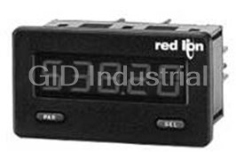
Red Lion Controls DT900020 RATE INDICATOR ADJ RED BACKLIGHT 9 V ~ 28 V LCD Backlit
Part Number
DT900020
Price
Request Quote
Manufacturer
RED LION CONTROLS
Lead Time
Request Quote
Category
TIMERS, COUNTER & METERS
Features
- 0.46 INCH (11.68 mm) HIGH DIGITS
- ACCEPTS MAGNETIC OR LOGIC TYPE SIGNAL INPUTS
- ADJUSTABLE TIMEBASE FROM 1 TO 7 SECONDS
- DESIGNED FOR MEDIUM/HIGH SPEED APPLICATIONS
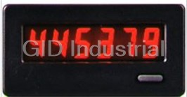
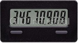
- LCD, POSITIVE REFLECTIVE OR NEGATIVE TRANSMISSIVE WITH YELLOW/GREEN OR RED BACKLIGHTING
- LITHIUM BATTERY PROVIDES OVER 7 YEARS OF CONTINUOUS OPERATION (Battery included)
- NEMA 4X/IP65 SEALED FRONT PANEL BEZEL
- RATE MULTIPLIER FROM 0.0001 TO 1.9999
- SELECTABLE DECIMAL POINTS
Datasheet

Extracted Text
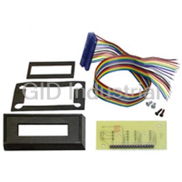
Bulletin No. DT9-C Drawing No. LP0534 Released 4/07 Tel +1 (717) 767-6511 Fax +1 (717) 764-0839 www.redlion.net DITAK 9 - ADJUSTABLE TIMEBASE 5-DIGIT RATE INDICATOR z DESIGNED FOR MEDIUM/HIGH SPEED APPLICATIONS z LCD, POSITIVE REFLECTIVE OR NEGATIVE TRANSMISSIVE WITH YELLOW/GREEN OR RED BACKLIGHTING z 0.46 INCH (11.68 mm) HIGH DIGITS z ADJUSTABLE TIMEBASE FROM 1 TO 7 SECONDS z RATE MULTIPLIER FROM 0.0001 TO 1.9999 z SELECTABLE DECIMAL POINTS z LITHIUM BATTERY PROVIDES OVER 7 YEARS OF CONTINUOUS OPERATION (Battery included) z NEMA 4X/IP65 SEALED FRONT PANEL BEZEL z ACCEPTS MAGNETIC OR LOGIC TYPE SIGNAL INPUTS DESCRIPTION SPECIFICATIONS The DITAK 9 is a self-powered rate indicator designed to operate in 1. DISPLAY: 5-Digit LCD, 0.46" (11.68 mm) high digits. medium/high speed applications. It is ideal for use with magnetic pick-ups or 2. POWER SOURCE: Internal 3.0 V lithium battery provides over 7 years of other bi-polar sensors operating at a minimum of 30 Hz*. The unit features continuous service (battery life is dependent upon usage). selectable timebase, rate multiplier, and decimal points via two front panel 3. BACKLIGHT POWER REQUIREMENTS: 9 to 28 VDC @ 35 mA. pushbuttons. It has a 5-digit LCD Display with 0.46" high digits that are available Above 26 VDC, derate operating temperature to 50°C. in positive image reflective (black digits, reflective background) or negative Must use the MLPS or a Class 2 or SELV rated power supply. image transmissive red or yellow/green (illuminated digits, dark background). 4. SIGNAL INPUT: 0 to 10 KHz from a magnetic or bi-polar output (with a Backlight version units require power from an external 9 to 28 VDC supply. 50% duty cycle). Min. input sensitivity is 0.9 V. Max. input = 28 V. The unit is constructed of a lightweight, high impact plastic case with a clear 5. TIMEBASE: Adjustable in 1 sec increments via front panel. Timebase viewing window. The sealed front panel meets NEMA 4X/IP65 specifications ranges from 1 second to 7 seconds; 0.05% accuracy. for wash-down and/or dusty environments, when properly installed. A Ditak 9 6. CONSTRUCTION: High impact plastic case with clear viewing window unit can be mounted in the same panel cut-out as the earlier Ditak 7 units. (Panel gasket and mounting clip included). Installation Category I, Pollution The optional Micro Line/Sensor Power Supply (MLPS1000) is designed to Degree 2. attach to the rear of an installed backlight version Ditak 9. The optional supply 7. CERTIFICATIONS AND COMPLIANCES: can be powered from an 85 to 250 VAC source, and can provide power for the SAFETY backlighting of a unit and a sensor. The maximum current draw for the sensor IEC 1010-1, EN 61010-1: Safety requirements for electrical equipment for is 45 mA. measurement, control, and laboratory use, Part 1. IP65 Enclosure rating (Face only), IEC 529 * - For slow speed applications with low pulse rates, it is recommended to use Type 4X Enclosure rating (Face only), UL50 the CUB5 Counter/Rate Indicator. ELECTROMAGNETIC COMPATIBILITY Emissions and Immunity to EN 61326 SAFETY SUMMARY Electrostatic discharge EN 61000-4-2 Criterion A All safety related regulations, local codes and instructions that appear in the 4 kV contact discharge manual or on equipment must be observed to ensure personal safety and to 8 kV air discharge prevent damage to either the instrument or equipment connected to it. If Electromagnetic RF fields EN 61000-4-3 Criterion A equipment is used in a manner not specified by the manufacturer, the protection 10 V/m provided by the equipment may be impaired. Fast transients (burst) EN 61000-4-4 Criterion A 2 kV power 2 kV signal CAUTION: Risk of Danger. Surge EN 61000-4-5 Criterion A Read complete instructions prior to 2 kV power installation and operation of the unit. 1 kV signal RF conducted interference EN 61000-4-6 Criterion A 10 V/rms Note: Recommended minimum clearance (behind the panel) for DIMENSIONS In inches (mm) mounting clip installation is 2.15" (54.6) H x 3.00" (76.2) W. 1 SPECIFICATIONS (Cont’d) BLOCK DIAGRAM Power Frequency magnetic fields EN 61000-4-8 Criterion A 30 A/m Voltage dip/interruptions EN 61000-4-11 Criterion A 0.5 cycle Emissions EN 55022 Class B Notes: 1. Criterion A: Normal operation within specified limits. Refer to the EMC Installation Guidelines section of this bulletin for additional information. 8. ENVIRONMENTAL CONDITIONS: Operating Temperature: 0 to 75°C (Above 50°C derate backlight operating voltage to 26 VDC max.) Storage Temperature: -30 to 80°C Operating and Storage Humidity: 85% max. relative humidity (non- condensing) from 0°C to 75°C. Altitude: Up to 2000 meters 9. WEIGHT: 3.3 oz (93.5 g) grounded. This is especially useful in applications where cable runs are long EMC INSTALLATION GUIDELINES and portable two-way radios are used in close proximity or if the installation Although this unit is designed with a high degree of immunity to is near a commercial radio transmitter. ElectroMagnetic Interference (EMI), proper installation and wiring methods 3. Signal or Control cables within an enclosure should be routed as far away as must be followed to ensure compatibility in each application. The type of the possible from contactors, control relays, transformers, and other noisy electrical noise, source or coupling method into the unit may be different for components. various installations. In extremely high EMI environments, additional measures 4. In extremely high EMI environments, the use of external EMI suppression may be needed. Cable length, routing and shield termination are very important devices, such as ferrite suppression cores, is effective. Install them on Signal and can mean the difference between a successful or a troublesome installation. and Control cables as close to the unit as possible. Loop the cable through the Listed below are some EMC guidelines for successful installation in an core several times or use multiple cores on each cable for additional protection. industrial environment. Install line filters on the power input cable to the unit to suppress power line 1. Use shielded (screened) cables for all Signal and Control inputs. The shield interference. Install them near the power entry point of the enclosure. The (screen) pigtail connection should be made as short as possible. The following EMI suppression devices (or equivalent) are recommended: connection point for the shield depends somewhat upon the application. Ferrite Suppression Cores for signal and control cables: Listed below are the recommended methods of connecting the shield, in order Fair-Rite # 0443167251 (RLC #FCOR0000) of their effectiveness. TDK # ZCAT3035-1330A a. Connect the shield only at the panel where the unit is mounted to earth Steward #28B2029-0A0 ground (protective earth). Line Filters for input power cables: b. Connect the shield to earth ground at both ends of the cable, usually when Schaffner # FN610-1/07 (RLC #LFIL0000) the noise source frequency is above 1 MHz. Schaffner # FN670-1.8/07 c. Connect the shield to common of the unit and leave the other end of the Corcom #1VR3 shield unconnected and insulated from earth ground. Note: Reference manufacturer’s instructions when installing a line filter. 2. Never run Signal or Control cables in the same conduit or raceway with AC 5. Long cable runs are more susceptible to EMI pickup than short cable runs. power lines, conductors feeding motors, solenoids, SCR controls, and Therefore, keep cable runs as short as possible. heaters, etc. The cables should be run in metal conduit that is properly Variable Frequency AC Inputs, Signal Source Powered WIRING CONNECTIONS The electrical connections are made via rear screw-clamp terminals located on the back of the unit. All conductors should meet voltage and current ratings for each terminal. Also cabling should conform to appropriate standards of good installation, local codes and regulations. It is recommended that power supplied to the unit (AC or DC) be protected by a fuse or circuit breaker. When wiring the unit, use the label to identify the wire position with the proper function. Strip the wire, leaving approximately 1/4" bare wire exposed (stranded wires should be tinned with solder). Insert the wire into the screw-clamp terminal and tighten the screw until the wire is clamped tightly. Each terminal can accept up to two #14 AWG wires. Variable Frequency AC Inputs, Signal Source Powered The backlighting for a backlight version unit is powered between the V+ Minimum V for operation is 0.9 V peak. AC Terminal and the Common Terminal. Logic Pulse Inputs From Other Circuits & Sensors 2 INSTALLATION ENVIRONMENT The unit should be installed in a location that does not exceed the maximum operating temperature and provides good air circulation. Placing the unit near INSTALLATION devices that generate excessive heat should be avoided. The Ditak 9 meets NEMA 4X/IP65 requirements for indoor use, when The bezel should be cleaned only with a soft cloth and neutral soap product. properly installed. The units are intended to be mounted into an enclosed Do NOT use solvents. Continuous exposure to direct sunlight may accelerate panel. A sponge rubber gasket, mounting clip, two screws, and nut fasteners the aging process of the bezel. are provided to install and seal the unit in the panel cut-out. The following procedure assures proper installation: 1. Cut panel opening to specified dimensions. Remove burrs and clean panel opening. 2. Slide the panel gasket over the rear of the unit to the back of the bezel. 3. Slide nut fastener into slot on mounting clip and then insert mounting screw through nut on both sides of mounting clip. Tip of mounting screw should NOT project through hole on clip. 4. Install Ditak unit through panel cut-out. 5. Slide mounting clip over rear of unit until clip is against back of panel. The mounting clip and Ditak housing have a latching feature to hold the unit in place until tightened. Note: Hold the Ditak front bezel in place when sliding the mounting clip into position. 6. Alternately tighten each mounting screw to ensure uniform gasket pressure. Visually inspect the gasket for proper seal. The gasket should be compressed approximately 75 to 80% of its original thickness. 7. If the gasket is not adequately compressed and the mounting screws cannot be tightened any further, loosen mounting screws and insure that the clip is latched as close as possible to the panel. 8. Repeat step #6 for tightening the mounting screws. RATE MULTIPLIER PROGRAMMING MENU The Ditak 9 has a Rate Multiplier (RM) selection range from 0.0001 to 1.9999. See Programming Calculations to determine the calculated value. After entering the programming mode, the least significant digit will be flashing. To increment this digit, press the SEL button. After the value 9, the digit will start over at 0. To move to the next digit press PAR and then that digit can be changed by pressing SEL. When reaching the most significant digit, pressing PAR will advance the meter to the Decimal Point selection. DECIMAL POINT SELECTION The selection of the decimal point position for the display (DDP) is Note: The display changes on “PAR” or “SEL” push button release. accomplished by repeatedly pressing SEL. This selection will always default to 0.0000 when advancing to it from the Rate Multiplier selection. By pressing PAR, the shown decimal point selection is entered and the Time base selection is shown. PROGRAMMING TIMEBASE SELECTION From the factory, the Ditak 9 is programmed with a fixed 1 second timebase The Ditak 9 has a Time Base selection range from 1 second to 7 seconds. See to read directly in HZ or RPM with a 60 tooth gear To enter the programming Programming Calculations to determine the calculated Rounded Time Base mode, place a jumper between the Push Button Enable (P. B. En.) Terminal and (RTB) value. The value is changed by pressing SEL. The value is entered by the Common Terminal. Once the jumper is connected the programming buttons pressing PAR and the Main Display/Run Mode is shown. are now activated. The Programming Mode consists of three selections; Rate Note: The position of the decimal point has no effect on this selection. Multiplier, Decimal Point, and Timebase. There is a fourth display which is the main display or run mode. Once programming is complete, the unit must be MAIN DISPLAY/RUN MODE returned to the main display before exiting the programming mode to obtain This display follows the Timebase Selection. The unit must be in this mode to normal operation. exit the Programming Mode and have the unit display properly. The push button enable jumper can be removed after the Ditak 9 is returned to the main display. 3 PROGRAMMING CALCULATIONS (Select one of the following) USING KNOWN RPM USING KNOWN PULSES PER UNIT An amusement park director wants his parking tram operators to keep their A newspaper company wants to know the line speed of their press to tenths speed under a certain limit. He has a magnetic sensor looking at a shaft on the of feet per minute. They have an encoder that gives 125 pulses per foot. The tram with 30 pulses per revolution. When the shaft is turning at 50 RPM he Ditak 9 is programmed as follows: wants the meter to show 15.5. The Ditak 9 is programmed as follows: TF = Time Factor DDP = Display Decimal Point DR = Desired Reading PPU = Pulses Per (Single) Unit DDP = Display Decimal Point TF: = Use one of the following numbers in the formula for the Time Factor: RPM = Revolutions Per Minute Per second = 1 PPR = Pulses Per Revolution Per minute = 60 DDP: Use the following corresponding numbers in the formula for the Display Per hour = 3600 Decimal Point: DDP: Use the following corresponding numbers in the formula for the Display 0 = 1 Decimal Point: 0.0 = 10 0 = 1 0.00 = 100 0.0 = 10 0.000 = 1000 0.00 = 100 RPM = 50 0.000 = 1000 Required minimum pulses per (single) unit: PPR = 30 Per second = 0.07 DR = 15.5 Per minute = 4.4 (multiply this value by DDP) DDP = 10 Per hour = 259.0 HERTZ (HZ) = RPM x PPR = 50 x 30 = 25 PPU = 125 (pulses per foot) 60 60 DDP = 10 (for tenths of a foot) TF = 60 (for per minute) CALCULATED TIME BASE = DR x DDP = 15.5 x 10 = 6.2 HZ 25 CALCULATED TIME BASE = TF x DDP = 60 x 10 = 4.8 PPU 125 ROUNDED TIME BASE (RTB) = 6 ROUNDED TIME BASE (RTB)= 5 REMAINDER MULTIPLIER (RM) = DR x DDP = 15.5 x 10 = 1.0333 REMAINDER MULTIPLIER (RM) = TF x DDP = 60 x 10 = 0.9600 RTB x HZ 6 x 25 RTB x PPU 5 x 125 RM = 1.0333 Decimal = 0.0 RM = 0.9600 RTB = 6 Decimal = 0.0 RTB = 5 ROUNDED TIME BASE (RTB) = Round Calculated Time Base to nearest whole number between 1-7. ROUNDED TIME BASE (RTB)= Round Calculated Time Base to nearest whole number between 1-7. If RM is greater than 1.9999, then remove a decimal location or add more pulses per revolution. If RM is greater than 1.9999, then remove a decimal location or add more pulses per unit. ORDERING INFORMATION MODEL NO. DESCRIPTION PART NUMBER Adjustable Timebase Tachometer DT900000 Adjustable Timebase Tachometer DT900010 TROUBLESHOOTING DT9 with Yellow/Green Backlighting For further technical assistance, contact Technical Adjustable Timebase Tachometer DT900020 Support at the appropriate company numbers listed. with Red Backlighting MLPS MLPS Micro Line Sensor/Power Supply MLPS1000 For more information on Pricing, Enclosures & Panel Mount Kits refer to the RLC Catalog or contact your local RLC distributor. Red Lion Controls AP Red Lion Controls Red Lion Controls BV 31, Kaki Bukit Road 3, 20 Willow Springs Circle Printerweg 10 #06-04/05 TechLink York PA 17406 NL - 3821 AD Amersfoort Singapore 417818 Tel +1 (717) 767-6511 Tel +31 (0) 334 723 225 Tel +65 6744-6613 Fax +1 (717) 764-0839 Fax +31 (0) 334 893 793 Fax +65 6743-3360
Frequently asked questions
What makes Elite.Parts unique?

What kind of warranty will the DT900020 have?
Which carriers does Elite.Parts work with?
Will Elite.Parts sell to me even though I live outside the USA?
I have a preferred payment method. Will Elite.Parts accept it?


What they say about us
FANTASTIC RESOURCE
One of our top priorities is maintaining our business with precision, and we are constantly looking for affiliates that can help us achieve our goal. With the aid of GID Industrial, our obsolete product management has never been more efficient. They have been a great resource to our company, and have quickly become a go-to supplier on our list!
Bucher Emhart Glass
EXCELLENT SERVICE
With our strict fundamentals and high expectations, we were surprised when we came across GID Industrial and their competitive pricing. When we approached them with our issue, they were incredibly confident in being able to provide us with a seamless solution at the best price for us. GID Industrial quickly understood our needs and provided us with excellent service, as well as fully tested product to ensure what we received would be the right fit for our company.
Fuji
HARD TO FIND A BETTER PROVIDER
Our company provides services to aid in the manufacture of technological products, such as semiconductors and flat panel displays, and often searching for distributors of obsolete product we require can waste time and money. Finding GID Industrial proved to be a great asset to our company, with cost effective solutions and superior knowledge on all of their materials, it’d be hard to find a better provider of obsolete or hard to find products.
Applied Materials
CONSISTENTLY DELIVERS QUALITY SOLUTIONS
Over the years, the equipment used in our company becomes discontinued, but they’re still of great use to us and our customers. Once these products are no longer available through the manufacturer, finding a reliable, quick supplier is a necessity, and luckily for us, GID Industrial has provided the most trustworthy, quality solutions to our obsolete component needs.
Nidec Vamco
TERRIFIC RESOURCE
This company has been a terrific help to us (I work for Trican Well Service) in sourcing the Micron Ram Memory we needed for our Siemens computers. Great service! And great pricing! I know when the product is shipping and when it will arrive, all the way through the ordering process.
Trican Well Service
GO TO SOURCE
When I can't find an obsolete part, I first call GID and they'll come up with my parts every time. Great customer service and follow up as well. Scott emails me from time to time to touch base and see if we're having trouble finding something.....which is often with our 25 yr old equipment.
ConAgra Foods