

 Manufacturers
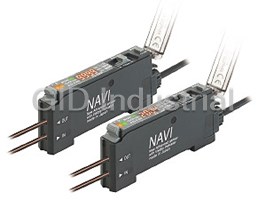
PANASONIC FX-411

Description
Panasonic FX-411 Sensor - FX-411 Standard Type 12-24VDC NPN
Part Number
FX-411
Price
Request Quote
Manufacturer
PANASONIC
Lead Time
Request Quote
Category
PRODUCTS - F
Specifications
Ambient humidity
35 to 85 % RH, Storage: 35 to 85 % RH
Ambient illuminance
Incandescent light: 3,000 lx or less at the light-receiving face
Ambient temperature
-10 to +55 °C -14 to +131 °F (If 4 to 7 units are connected in cascade: -10 to +50 °C +14 to +122 °F, if 8 to 16 units are connected in cascade: -10 to +45 °C +14 to +113 °F)(No dew condensation or icing allowed), Storage: -20 to +70 °C -4 to +158 °F
Automatic interference prevention function
Incorporated (Up to four sets of fiber heads can be mounted close together. However, U-LG mode is 8 fiber heads.)(Note 4)
Cable length
Total length up to 100 m 328.084 ft (50 m 164.042 ft for 5 to 8 units, 20 m 65.617 ft for 9 to 16 units) is possible with 0.3 mm2, or more, cable.
EMC
EN 60947-5-2
Emitting element (modulated)
Red LED
Insulation resistance
20 MO, or more, with 250 V DC megger between all supply terminals connected together and enclosure (Note 5)
Material
Enclosure: Heat-resistant ABS, Case cover: Polycarbonate
Operation indicator
Orange LED (lights up when the output is ON)
Output
NPN open-collector transistor Maximum sink current: 100 mA
Output operation
Switchable either Light-ON or Dark-ON
Peak emission wevelength
650 nm 0.026 mil
Pollution degree
3 (Industrial environment)
Power consumption
Normal operation: 960 mW or less (Current consumption 40 mA or less at 24 V supply voltage) ECO mode: 840 mW or less (Current consumption 35 mA or less at 24 V supply voltage)
Response time
150 µs or less (FAST), 500 µs or less (STD), 4.5 ms or less (U-LG) selectable with setting switch
Shock resistance
98 m/s2 acceleration (10 G approx.) in X, Y and Z directions for five times each
Short-circuit protection
Incorporated
Stability indicator
Green LED (lights up under stable light received condition or stable dark condition)
Supply voltage
12 to 24 V DC ± 10 % Ripple P-P 10 % or less
Timer function
Incorporated with variable ON-delay / OFF-delay / ONE SHOT timer, switchable either effective or ineffective. [Timer period (Note 3): 1 ms to 3 sec. approx. (1 to 10 ms: Setting possible in units of 1 ms, 10 to 100 ms: Setting possible in units of 10 ms, 100 to 500 ms: Setting possible in units of 50 ms, 500 ms to 1 sec.: Setting possible in units of 100 ms, 1 to 3 sec.: Setting possible in units of 500 ms)]
Utilization category
DC-12 or DC-13
Vibration resistance
10 to 150 Hz frequency, 0.75 mm 0.030 in amplitude in X, Y and Z directions for two hours each
Voltage withstandability
1,000 V AC for one min. between all supply terminals connected together and enclosure (Note 5)
Weight
Net weight: 20 g approx., Gross weight: 30 g appro
Features
- Easy-to-understand operating panel layout
- Enhanced user interface
- Excellent workability and ease of maintenance
- Four-chemical emitting element in combination with a built-in auto power control circuit
- Incident light intensity and threshold value are displayed simultaneously
- Large endless adjuster
- light emitting amount selection feature
- Stronger lighting
Datasheet

Extracted Text
PHOTOELECTRIC SENSOR
DIGITAL FIBER SENSOR
FX-411SERIES
Conforming to
EMC Directive
Digital dual display Large adjuster
Just ‘Look’ and ‘Turn’
Simple, easy-to-use fiber sensor
Fiber sensors that are easy to understand
and use, even for beginners
Operation is so simple that it can be understood without even needing to look at an
instruction manual.
This is a new type of fiber sensor that emphasizes convenience in the workplace.
Find the threshold value and incident light intensity
just by ‘Looking’
Use a screwdriver to adjust simply by ‘Turning’
Incident light intensity
Threshold value
Stability indicator
Output indicator
Industry’s smallest
Industry’s smallest
m
m
in its class
in its class
mFor digital dual-display fiber
sensors
As of April 2005 and based
on research conducted by
SUNX.
Basic performance that is central to the design stage has been upgraded
Beam power greatly increased to Improved stability over both Three types are available,
give strong performance under long and short terms with red, blue and green light
Red LED type
adverse environments The red LED type sensors have a ‘four-chemical emitting Different sensors can be selected to suit the
element’ which maintains stability of light emissions for application.
The beam power has been greatly increased. This
long-term operation. Furthermore, all models have an ‘APC
means a longer sensing distance and less trouble
(Auto Power Control) circuit’ which improves stability at
from problems such as dust. These sensors have
times such as when the power is turned on. These features
ample performance for workplace needs.
improve overall stability compared to previous models.
● Stable sensing comparison
1,500 mm
FX-411
Short-term stability
59.055 in
FX-411 (Red LED type)
Previous 1,000 mm
Three-chemical
emitting element,
models 39.370 in
Deviation
Without APC
(for U-LG mode)
1.5 times 1.5 times
previous previous
models models
Long-term stability
mFor FT-FM2 thru-beam type fiber
Time
1
Light emitting amount
Dual display Large adjuster
Explanations of how to operate the sensors can be given remotely by telephone with ease.
●
● Operations are carried out using basic tools (screwdrivers), which reduces the possibility
Therefore
of accidental operating errors.
Work-
Emphasis on being easy to understand and easy to use place
Incident light intensity and Large endless adjuster Easy-to-understand operating panel layout
threshold value are displayed
New concept
The threshold value adjuster and operation
simultaneously mode switch are large and easy to see, and
Standard screwdrivers can be used to turn the
they can be operated with the same
The incident light intensity and threshold adjuster as well as
sensitivity as general-purpose photoelectric
value can be checked at the same time with precision screwdrivers.
sensors. Functions which are not commonly
no operations needed. In addition, no In addition, an ‘endless’
used can be operated using a non-obtrusive
complex mode settings are needed when mechanism is used
setting switch.
the values are adjusted. which eliminates the
Operation mode swich
possibility of any
damage being caused
by turning the adjuster
Everyday-use
too far.
screwdriver is OK
Setting
Threshold value adjuster switch
m
mRotation Speed Sensitivity
Immediate setting possible using the R.S.S. adjuster
The sensitivity amount changes depending on the rotation speed of the adjuster, so that
adjustment can be carried out speedily.
Amount of
change
(digit)
100
30�
10 S Slower lower Faster Faster
1
Adjuster
rotation speed
No need for the fine changes
in force required for
photoelectric sensors.
Design
Excellent workability and ease of maintenance
The same quick-connection cable that is used for sensors such as the FX-300 series of digital fiber sensors is used. This means that they can be
used together with other types of sensors such as laser sensors, and the number of power supply cables can be reduced.
Laser sensor Fiber sensor Fiber sensor Fiber sensor
LS-401 FX-411 FX-411B FX-411G
Sub cable
CN-71-C�
Quick-connection cables can be used for
power supply cascade wiring.
Main cable
CN-73-C� Both main and sub units utilize the same
amplifier body.
Up to a maximum 16 sensors can be connected together
The sensors can be connected together with other sensors such as the
Output line 1 Output line 2 Output line 3 Output line 16
Power
FX-300 series of digital fiber sensors and the GA-311 of inductive
supply
cable Main cable Sub cable
proximity sensors. In addition, the SC series of sensor PLC connection
A single output line is used, so that wiring can be greatly reduced
units with MIL connector compatibility can also be used to further
and space savings can be obtained.
reduce the amount of wiring.
2
Adjustment in units of Adjustment in units of
1 digit is also easy 1 digit is also easy
1 digit equals 30�
Convenient functions backed up
by technology
Red LED type New concept
Ideal for dealing with saturation / Light-emitting amount selection function
In cases where the incoming light level can become saturated, such as during close-
range sensing or when sensing transparent or minute objects, the sensor’s light-
emitting amount can be adjusted to provide more stable sensing without changing the
response time.
Level 4
FT-WA8
Level 3
Light-emitting amount
can be changed
Level 2
without changing
response time.
Level 1
Wire breakage detection
Equipped with 3 types timers Interference prevention for up to 8 sets fiber heads (for U-LG)
Equipped with OFF-delay The optical transmission function allows up to a maximum of eight
/ ON-delay / ONE SHOT sets of fiber heads (four sets for FAST and STD settings) to be
Time chart For L-ON
Beam-
timer. installed in contact with each other without mutual interference
received
Timer period: occurring. (Set automatically when power is turned on.)
Sensing Beam-
( )
1 to 500 ms approx. condition interrupted
ON
T1
ON-delay
OFF
FD-FM2
ON
T1 T1
OFF-delay OFF
Dog
ON
T1 T1
ONE SHOT OFF
Digital display upside-down / off function Hold function
The digital display can be turned upside-down if required to suit the Peak and bottom hold values for the incident light intensity can be
setup location. In addition, a stability indicator is also provided, so displayed. This is useful for checking the incident light intensity
that the amount of light-receiving excess can be checked even during tasks such as drop detection.
when the display is turned off.
In addition, the peak and bottom values can be checked while
looking at the threshold value, which makes adjustment much
When digital
easier.
display is
upside down
(turned ON)
Adjuster is used so that operation can be
Displayed sequentially
Displayed sequentially
carried out confidently even when upside down.
Hold function
setting display
When digital
display is off
(Eco ON)
Bottom hold
Stability indicator FT-A8
amount display
Excess amount can be seen even when display is off
Peak hold
Key lock function* prevents wrong operation
Drop detection of minute objects amount display
This prevents the operator from changing the threshold value by
mistake.
Press and hold setting switch for 5 seconds
Available in models manufactured since July 2005.
*
3
FX-411
ORDER GUIDE
Connector type amplifiers Quick-connection cable is not supplied with the amplifier. Please order it separately.
Type Appearance Model No. Emitting element Output
FX-411 Red LED
NPN open-collector
FX-411B Blue LED
transistor
FX-411G Green LED
FX-411P Red LED
PNP open-collector
FX-411BP Blue LED
transistor
FX-411GP Green LED
Quick-connection cable is not supplied with the amplifier. Please order it separately.
Quick-connection cables
Main cable
Type Model No. Description
• CN-73-C�
CN-73-C1 Length: 1 m 3.281 ft
2
Main cable 0.15 mm 3-core cabtyre cable, with connector on one end
CN-73-C2 Length: 2 m 6.562 ft
(3-core) Cable outer diameter: "3.0 mm "0.118 in
Length: 5 m 16.404 ft
CN-73-C5
Sub cable
CN-71-C1 Length: 1 m 3.281 ft
2
Sub cable 0.15 mm 1-core cabtyre cable, with connector on one end • CN-71-C�
Length: 2 m 6.562 ft
CN-71-C2
(1-core) Cable outer diameter: "3.0 mm "0.118 in
Length: 5 m 16.404 ft
CN-71-C5
End plates End plates are not supplied with the amplifier. Please order them separately when the amplifiers are mounted in cascade.
Appearance Model No. Description
When cascading multiple amplifiers, or when it moves
depending on the way it is installed on a DIN rail, these end
plates ensure that all amplifiers are mounted together in a
MS-DIN-E
secure and fully connected manner.
Two pcs. per set
OPTIONS
Amplifier mounting bracket
• MS-DIN-2
Designation Model No. Description
Amplifier mounting
Mounting bracket for amplifier
MS-DIN-2
bracket
10 sets of 2 communication window seals and 1 connector seal
Communication window seal:
Fiber amplifier protective seal
It prevents malfunction due to transmission signal from another
Fiber amplifier
• FX-MB1
FX-MB1 amplifier, as well as, prevents effect on another amplifier.
protective seal
Communication
Connector seal:
window seal
It prevents contact of any metal, etc., with the pins of the quick-
connection cable.
Connector seal
4
Connector type
PNP output NPN output
FX-411
LIST OF FIBERS (TYPICAL)
Please contact our office for details on models which are not shown below.
Thru-beam type (one pair set)
� : U-LG � : FAST
Fiber cable
Sensing range (mm in)(Note 1)
Shape of fiber head Bending
� : STD
Type length Model No.
radius
(mm in)
Red LED Blue LED Green LED : Free-cut
Lens mountable
2,000 78.740 440 17.323 220 8.661
M4
530 20.866 110 4.331 55 2.165
FT-B8
400 15.748 75 2.953 40 1.575
R25
Lens mountable 1,500 59.055 230 9.055 120 4.724
M4
340 13.386 60 2.362 30 1.181
FT-FM2
2 m
240 9.449 40 1.575 22 0.866
6.562 ft
Lens mountable 950 37.402 170 6.693 100 3.937
M4
290 11.417 45 1.772 26 1.024
R1 FT-W8
200 7.874 30 1.181 18 0.709
Lens mountable 1,200 47.244 240 9.449 120 4.724
M4
1 m
320 12.598 64 2.520 32 1.260
R10 FT-P81X
3.281 ft
230 9.055 45 1.772 22 0.866
Tough flexible
450 17.717 85 3.346 38 1.496
M3
130 5.118 20 0.787 10 0.394
R25 FT-NFM2
2 m
85 3.346 14 0.551 7 0.276
6.562 ft
300 11.811 48 1.890 26 1.024
M3
80 3.150 8 0.315 5 0.197
R1 FT-W4
2 m
55 2.165 5 0.197 3 0.118
6.562 ft
Wide area sensing Note 2 Note 2 3,500 137.795 900 35.433 400 15.748
1,500 59.055 300 11.811 150 5.906
FT-WA8
R1
1,100 43.307 220 8.661 110 4.331
sensing width 11 mm 0.433 in
2 m
N Note 2 ote 2 3,500 137.795 900 35.433 400 15.748
W4.2�H31�D13.5 6.562 ft
1,500 59.055 300 11.811 150 5.906
R10 FT-A8
0.165�1.220�0.531
1,100 43.307 220 8.661 110 4.331
Notes: 1) Please take care that the sensing range of the free-cut type fiber may be reduced by 20 % max. depending upon how the fiber is cut.
2) The fiber cable length practically limits the sensing range to 3,500 mm 137.795 in long.
Reflective type
� : U-LG � : FAST
Fiber cable
Sensing range (mm in)(Note 1, 2)
Shape of fiber head � : STD Bending
Type length Model No.
radius
(mm in)
Red LED Blue LED Green LED
: Free-cut
650 25.591 160 6.299 86 3.386
M6
180 7.087 40 1.575 21 0.827
FD-B8
120 4.724 26 1.024 14 0.551
R25
Coaxial
460 18.110 90 3.543 46 1.811
M6
110 4.331 23 0.906 12 0.472
FD-FM2
2 m
80 3.150 15 0.591 8 0.315
6.562 ft
M6
300 11.811 53 2.087 28 1.102
70 2.756 11 0.433 7 0.276
FD-W8
R1
50 1.969 8 0.315 4 0.157
M6 280 11.024 70 2.756 32 1.260
1 m
80 3.150 16 0.630 8 0.315
R10 FD-P81X
3.281 ft
55 2.165 10 0.394 5 0.197
Tough flexible
170 6.693 35 1.378 16 0.630
M4
40 1.575 8 0.315 4 0.157
R25 FD-NFM2
2 m
30 1.181 5 0.197 2 0.079
6.562 ft
Coaxial � Lens mountable
150 5.906 26 1.024 12 0.472
32 1.260 5 0.197 3 0.118
R2 FD-WG4
25 0.984 3 0.118 2 0.079
2 m
220 8.661 48 1.890 20 0.787
M4
6.562 ft
52 2.047 11 0.433 5 0.197
FD-G4
R25
38 1.496 8 0.315 3 0.118
Lens mountable (FX-MR3, FX-MR6)
200 7.874 50 1.969 22 0.866
M3
45 1.772 11 0.433 6 0.236
1 m 3.281 ft FD-G6X
R10
35 1.378 6 0.236 4 0.157 (Note 3)
Coaxial Tough flexible
Notes: 1) The sensing range is specified for white non-glossy paper [200�200 mm 7.874�7.874 in (FD-B8, FD-FM2, FD-W8, FD-P81X: 400�400 mm
15.748�15.748 in)] as the object.
2) Please take care that the sensing range of the free-cut type fiber may be reduced by 20 % max. depending upon how the fiber is cut.
3) The allowable cutting range is 700 mm 27.559 in from the end that the amplifier inserted.
5
Threaded type Special Threaded type
M3 M4 M6 Wide beam M3 M4
FX-411
SPECIFICATIONS
NPN output PNP output
Type
Red LED Blue LED Green LED Red LED Blue LED Green LED
Model No. FX-411 FX-411B FX-411G FX-411P FX-411BP FX-411GP
Item
Supply voltage
12 to 24 V DC�10 % Ripple P-P 10 % or less
Frequently asked questions
What makes Elite.Parts unique?

What kind of warranty will the FX-411 have?
Which carriers does Elite.Parts work with?
Will Elite.Parts sell to me even though I live outside the USA?
I have a preferred payment method. Will Elite.Parts accept it?
Why buy from GID?

Quality
We are industry veterans who take pride in our work

Protection
Avoid the dangers of risky trading in the gray market

Access
Our network of suppliers is ready and at your disposal

Savings
Maintain legacy systems to prevent costly downtime

Speed
Time is of the essence, and we are respectful of yours
Related Products

Request a Quote

The quote request has been received
Close

Facing challenges or have inquiries? Feel free to contact us!
Call Us +1-469-283-2440
What they say about us
FANTASTIC RESOURCE
One of our top priorities is maintaining our business with precision, and we are constantly looking for affiliates that can help us achieve our goal. With the aid of GID Industrial, our obsolete product management has never been more efficient. They have been a great resource to our company, and have quickly become a go-to supplier on our list!
Bucher Emhart Glass
EXCELLENT SERVICE
With our strict fundamentals and high expectations, we were surprised when we came across GID Industrial and their competitive pricing. When we approached them with our issue, they were incredibly confident in being able to provide us with a seamless solution at the best price for us. GID Industrial quickly understood our needs and provided us with excellent service, as well as fully tested product to ensure what we received would be the right fit for our company.
Fuji
HARD TO FIND A BETTER PROVIDER
Our company provides services to aid in the manufacture of technological products, such as semiconductors and flat panel displays, and often searching for distributors of obsolete product we require can waste time and money. Finding GID Industrial proved to be a great asset to our company, with cost effective solutions and superior knowledge on all of their materials, it’d be hard to find a better provider of obsolete or hard to find products.
Applied Materials
CONSISTENTLY DELIVERS QUALITY SOLUTIONS
Over the years, the equipment used in our company becomes discontinued, but they’re still of great use to us and our customers. Once these products are no longer available through the manufacturer, finding a reliable, quick supplier is a necessity, and luckily for us, GID Industrial has provided the most trustworthy, quality solutions to our obsolete component needs.
Nidec Vamco
TERRIFIC RESOURCE
This company has been a terrific help to us (I work for Trican Well Service) in sourcing the Micron Ram Memory we needed for our Siemens computers. Great service! And great pricing! I know when the product is shipping and when it will arrive, all the way through the ordering process.
Trican Well Service
GO TO SOURCE
When I can't find an obsolete part, I first call GID and they'll come up with my parts every time. Great customer service and follow up as well. Scott emails me from time to time to touch base and see if we're having trouble finding something.....which is often with our 25 yr old equipment.
ConAgra Foods