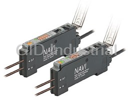
FZ-10 SERIES
Color Detection Fiber Sensor
PNP output Timer
type available
Reliable and precise
color discrimination
Conforming to
UL Recognition
EMC Directive
Red, green and blue LEDs Easy set up
FZ-10 incorporates red, green and blue Just pressing a button recognizes the reference color you want to detect as the
LEDs as its beam sources, which criterion. There are two methods to set the criterion, manual teaching and
promise longer lifetime and greater auto-teaching. The tolerance adjuster also allows you to set the tolerance of color
immunity against extraneous light than equivalence in 16 grades.
fluorescent lamps and are also mainte-
�Criterion
nance free.
Manual teaching Auto-teaching
Lenses
Place a workpiece bearing the reference Keep pressing the teaching button until a
workpiece bearing the reference color travels
color under the fiber head and press the
Fibers
past the fiber head.
teaching button.
Teaching
button Teaching button
Red LED
Green LED
Half mirrors
Blue LED
Place a workpiece,
Press the button,
and press the button.
and feed a workpiece.
Excellent color detectability
�Tolerance adjustment
Each of the red, green and blue com-
Reference color
(Criterion)
ponents is digitally processed so that
Precise judgment
Rough judgment
precise color discrimination is possible.
Tolerance adjuster Tolerance adjuster
FZ-10 can discriminate between white
The adjuster deter-
Turn the adjuster clock- Turn the adjuster coun-
and yellow or distinguish if a surface is 8 8
10 6 10 6
mines the tolerance of
wise. The closer it is to
terclockwise. The closer
plated or not, that could never be pos-
12 4 equivalence with re- 12 4
‘FINE’, finer is the set it is to the ‘ ’ mark,
spect to the reference
sible with conventional fiber sensors 14 FINE tolerance. 14 FINE coarser is the set toler-
color.
ance.
which were based on detection of light
intensity.
Narrow tolerance Wide tolerance
Can discriminate bet- Dully gold-plated surface
ween white and yel- is reliably detected.
low surfaces.
182
FZ-10 FX-11A FX-311 FX-CH FX-303 FX-302 FX-301
Fiber
FIBER SENSORS
Color Detection Analog Output Manually Set Bank Selection Unit Digital Setting Selection
FZ-10
APPLICATIONS
Detecting labels on different colored Evaluating if objects are plated or not Detecting seals on boxes
objects (Note 1)
It can reliably detect the presence of a
Even if objects are differently colored, Its precise color resolution discrim- seal on every package in the pharma-
FZ-10 reliably detects the same color inates a bare metal surface from a plat- ceutical, cosmetic, food, tobacco, and
label. ed metal surface. software industries.
Synchronizing
Synchronizing
sensor
Synchronizing
sensor
sensor
Notes: 1) FD-L52 fiber head (high precision type) or FD-L53 fiber head (extremely small spot type) is recommended for applications in which specular objects,
having a high reflective index are to be detected, e.g., evaluating if metal objects are plated or not.
FD-L54 fiber head (long sensing range type) is recommended for applications where the object wavers on the assembly line.
Notes: 2) FZ-10 may not be able to detect color depending on object shape, color, glossiness, etc. Please test before actual use and contact our office if you have
any questions.
Miniature & space-effective Four types of fibers are available High-speed response time: 1 ms
The amplifier is only W20�H31.5� The fiber can be selected according to Small traveling objects can be sensed
D67 mm W0.787�H1.240�D2.638 in the application and object size. The even on a high-speed production line,
in size and the fiber head is just 7 mm color of even a small object can be reli- due to its response time of 1 ms.
0.276 in, 8 mm 0.315 in or 12 mm ably detected.
0.472 in thick, so that it is mountable in
a tight space.
FD-L51 FD-L52
Small and
(Standard type) (High precision type)
fast
traveling
Amplifier
objects can
be reliably
sensed.
31.5 mm
1.240 in
Spot
Setting distance diameter
Setting distance Spot diameter 10 mm 0.394 in "2.5 mm
20 mm 0.787 in fixed " 0.098 in
"5 mm "0.197 in
fixed
67 mm 2.638 in
20 mm 0.787 in
FD-L53 FD-L54
(Extremely small spot type) (Long sensing range type)
Fibers
8 mm 8 mm
0.315 in 0.315 in
Spot diameter
"1 mm "0.039 in
Setting distance Setting distance
40 mm 1.575 in
5 mm 0.197 in fixed
fixed
Spot diameter "8 mm "0.315 in
FD-L52 fiber head (high precision type) or FD-L53 fiber head (extremely small spot type) is rec-
ommended for applications in which specular objects, having a high reflective index are to be
detected, e.g., evaluating if metal objects are plated or not.
7 mm 12 mm
FD-L54 fiber head (long sensing range type) is recommended for applications where the
0.276 in 0.472 in
object wavers on the assembly line.
183
Color Detection Analog Output Manually Set Bank Selection Unit Digital Setting Fiber
FIBER SENSORS
Selection
FZ-10 FX-11A FX-311 FX-CH FX-303 FX-302 FX-301
P D
FZ-10
ORDER GUIDE
Amplifiers
Type Appearance Model No. Emitting element Output
NPN output NPN open-collector
FZ-11
type
transistor
Red LED
Green LED
Blue LED
PNP open-collector
PNP output
FZ-11P
type transistor
Fibers
Type Appearance Setting distance Spot diameter Fiber cable length Model No.
20 mm 0.787 in
"5 mm "0.197 in
Standard 1 m 3.281 ft
FD-L51
(fixed)
(at the setting distance)
10 mm 0.394 in
"2.5 mm "0.098 in
High precision 1 m 3.281 ft
FD-L52
(fixed)
(at the setting distance)
"1 mm "0.039 in
Extremely small
5 mm 0.197 in (fixed) 1 m 3.281 ft
FD-L53
(at the setting distance)
spot
40 mm
"8 mm "0.315 in
Long sensing
1.575 in 1 m 3.281 ft
FD-L54
(at the setting distance)
range
(fixed)
Reference
Threaded head fiber
Color discrimination is also possible with FD-B8/FM2/G4 (standard fiber for the FX-301/302/303/311 series) in combination with the FZ-10 series amplifier.
As a standard fiber has a small head and is free-cut type, allowing you to cut the desired fiber cable length, it can be mounted in a narrow space.
FD-B8 FD-FM2 FD-G4
Setting distance: 8 mm 0.315 in (fixed) Setting distance: 5 mm 0.197 in (fixed) Setting distance: 4 mm 0.157 in (fixed)
M4
M6 M6
Caution: They cannot be used in an application which needs precision sensing.
Accessory
• MS-DIN-3
• (Amplifier mounting bracket)
OPTIONS
Universal sensor mounting stand
Using the arm which enables adjustment in the horizontal direction, sensing
Designation Model No. Description
can also be done from above an assembly line.
• MS-AJ1-F • MS-AJ2-F
MS-AJ1-F Horizontal mounting type 360� 360�
Universal sensor Mounting stand
rotation rotation
mounting stand assembly for
(Note) fiber
MS-AJ2-F Vertical mounting type
Height Height
360� 360�
adjustment: adjustment:
Note: Refer to p.332l for details of the universal sensor mounting stand.
rotation rotation
150 mm 150 mm
5.906 in 5.906 in
approx. approx.
20� 20�
20� 20�
Mounting hole
Mounting hole
Angle adjustment:�20° Angle adjustment:�20°
for M6 screw
for M6 screw
184
FZ-10 FX-11A FX-311 FX-CH FX-303 FX-302 FX-301
Fiber
FIBER SENSORS
Color Detection Analog Output Manually Set Bank Selection Unit Digital Setting Selection
FZ-10
SPECIFICATIONS
Amplifiers
Type NPN output PNP output
Model No. FZ-11 FZ-11P
Item
Applicable fibers FD-L51, FD-L52, FD-L53, FD-L54
Supply voltage 12 to 24 V DC�10 % Ripple P-P 10 % or less
Current consumption 45 mA or less
Sensing object
Opaque or translucent object larger than the spot diameter of the applicable fiber
NPN open-collector transistor PNP open-collector transistor
• Maximum sink current: 100 mA • Maximum source current: 100 mA
Output • Applied voltage: 30 V DC or less (between output and 0 V) • Applied voltage: 30 V DC or less (between output and�V)
• Residual voltage: 1 V or less (at 100 mA sink current) • Residual voltage: 1 V or less (at 100 mA source current)
0.4 V or less (at 16 mA sink current) 0.4 V or less (at 16 mA source current)
Utilization category
DC-12 or DC-13
Output operation Switchable either Coincident-ON or Incoincident-ON
Short-circuit protection Incorporated
Response time
1 ms or less (3 ms or less when auto-teaching has been engaged)
Power indicator: Green LED (lights up when the power is ON, blinks during auto-teaching)
Operation indicator: Red LED (lights up when the output is ON)
Indicators
mBoth blink alternately when a manual teaching error occurs
Both blink simultaneously when the output is short-circuited
Timer function
Approx. 40 ms fixed OFF-delay timer (switchable either effective or ineffective)
Teaching
Button operation, Switchable either manual-teaching or auto-teaching
Tolerance Adjustable in 16 grades with the tolerance adjuster
Pollution degree 3 (Industrial environment)
Ambient temperature
�10 to�55 �C �14 to�131 �F (No dew condensation or icing allowed) (Note 1), Storage:�20 to�70 �C �4 to�158 �F
Ambient humidity
35 to 85 % RH, Storage: 35 to 85 % RH
Ambient illuminance
Sunlight: 10,000 ?x at the light-receiving face, Incandescent light: 3,000 ?x at the light-receiving face
EMC
EN 50081-2, EN 50082-2, EN 60947-5-2
Voltage withstandability 1,000 V AC for one min. between all supply terminals connected together and enclosure (Note 2)
Insulation resistance 20 MΩ, or more, with 250 V DC megger between all supply terminals connected together and enclosure (Note 2)
Vibration resistance
10 to 150 Hz frequency, 0.75 mm 0.030 in amplitude in X, Y and Z directions for two hours each
2
Shock resistance
100 m/s acceleration (10 G approx.) in X, Y and Z directions for three times each
Emitting element
Red LED • Green LED • Blue LED (modulated)
Material Enclosure: ABS, Case cover: Polycarbonate, Fiber lock lever: PPS
2
Cable 0.2 mm 3-core cabtyre cable, 2 m 6.562 ft long
2
Cable extension Extension up to total 100 m 328.084 ft is possible with 0.3 mm , or more, cable.
Weight
85 g approx.
Accessories
MS-DIN-3 (Amplifier mounting bracket): 1 pc., Adjusting screwdriver: 1 pc.
Notes: 1) The amplifier should be used under the ambient temperature of�15 �C to�35 �C �59 �F to�95 �F when the tolerance adjuster is set from the 1st
grade to the 4th grade, which provide fine color resolution.
Notes: 2) The voltage withstandability and the insulation resistance values given in the above table are for the amplifier only.
185
Environmental resistance
Color Detection Analog Output Manually Set Bank Selection Unit Digital Setting Fiber
FIBER SENSORS
Selection
FZ-10 FX-11A FX-311 FX-CH FX-303 FX-302 FX-301
FZ-10
SPECIFICATIONS
Fibers
Type Standard High precision Extremely small spot Long sensing range
Item Model No. FD-L51 FD-L52 FD-L53 FD-L54
Applicable amplifiers FZ-11 FZ-11P
,
Sensing range (Note 1) 14 to 24 mm 0.511 to 0.945 in 8 to 11 mm 0.315 to 0.433 in 4 to 6 mm 0.157 to 0.236 in 30 to 50 mm 0.181 to 1.969 in
Setting distance 20 mm 0.787 in (fixed) 10 mm 0.394 in (fixed) 5 mm 0.197 in (fixed) 40 mm 1.575 in (fixed)
Spot diameter (at setting distance) "5 mm 0.197 in "2.5 mm 0.098 in "1 mm 0.039 in "8 mm 0.315 in
Allowable bending radius R25 mm 0.984 in or more (Note 2)
Fiber cable length 1 m 3.281 ft
Ambient temperature �20 to�70 °C �4 to�158 °F (No dew condensation or icing allowed), Storage:�20 to�70 °C �4 to�158 °F
Ambient humidity 35 to 85 % RH, Storage: 35 to 85 % RH
Material Fiber core: Acrylic, Sheath: Polyethylene, Fiber head: Polycarbonate, Lens: Polyalylate (FD-L54: Acrylic)
Weight 15 g approx.
Notes: 1) The sensing range of each fiber is the range for which white non-glossy paper can be detected at the sensitivity for which teaching has been done with
a white non-glossy paper (50�50 mm 1.969�1.969 in) at the respective rated setting distance and at the 16th grade (d mark) of tolerance.
Notes: 2) If the fiber cable is bent at less than R25 mm 0.984 in or less, the detectability may deteriorate.
Notes: 3) Since fiber FD-L51 (standard type) is easily affected by specular reflection, it is possible that teaching may not be properly done or sensing may be
unstable if objects of high reflectivity (mirror, plated objects, copper foil, etc.) are sensed. When such objects are to be sensed, please use FD-L52 (high
precision type) or FD-L53 (extremely small spot type) and make sure that the projected optical beam is perpendicular to the object surface.
I/O CIRCUIT AND WIRING DIAGRAMS
FZ-11
NPN output type
I/O circuit diagram Wiring diagram
Color code
Brown
D
(Brown) �V
Load
�
Load Black 12 to 24 V DC
�10 %
� �
(Black) Output 12 to 24 V DC
Tr
�10 %
�
100 mA max. Blue
ZD
(Blue) 0 V
Internal circuit Users’ circuit
Symbols ... D : Reverse supply polarity protection diode
D
Z : Surge absorption zener diode
Tr : NPN output transistor
FZ-11P
PNP output type
I/O circuit diagram Wiring diagram
Color code
Brown
(Brown) �V
�
Black 12 to 24 V DC
ZD
Tr
100 mA max.
�10 %
�
12 to 24 V DC �
Load
�10 %
(Black) Output �
Blue
Load
D
(Blue) 0 V
Internal circuit Users’ circuit
Symbols ... D : Reverse supply polarity protection diode
ZD: Surge absorption zener diode
Tr : PNP output transistor
186
FZ-10 FX-11A FX-311 FX-CH FX-303 FX-302 FX-301
Fiber
FIBER SENSORS
Color Detection Analog Output Manually Set Bank Selection Unit Digital Setting Selection
Sensor circuit Sensor circuit
P D
FZ-10
PRECAUTIONS FOR PROPER USE Refer to p.1135l for general precautions.
Amplifier
Functional description
This product is not a safety sensor. Its use is not
intended or designed to protect life and prevent body
3
injury or property damage from dangerous parts of
machinery. It is a normal object detection sensor.
1 4
POWER OUT
Mounting
5
2
FZ–11
LOCK SET
How to mount the amplifier
LOCK SET
AUTO MANUAL
INVERSE NORMAL AUTO MANUAL
OFD NON
1 Fit the rear part of the amplifier 8
INVERSE NORMAL
10
6
6
12 4
on the attached amplifier mount- OFD NON
FINE
14
ing bracket (MS-DIN-3) or a TOLERANCE
7
8
35 mm 1.378 in width DIN rail.
TEACH
2 JAPAN
1
2 Press down the front part of the
9
amplifier on the amplifier mount-
Attached amplifier mounting
ing bracket (MS-DIN-3) or 35 mm
bracket or 35 mm 1.378 in width DIN rail
1.378 in width DIN rail to fit it.
Description Function
How to remove the amplifier
1
1 Push the amplifier forward.
2
1
Fiber lock lever Locks or unlocks fiber cables.
2 Lift up the front part of the
Lights up when the pow- Both blink alternately
amplifier to remove it. Power indicator
2
er is ON, blinks during when a manual teaching
(Green LED)
auto-teaching. error occurs.
Note: Please take care that if the front
Both blink simultaneously
part is lifted without pushing the
Operation indicator Lights up when the output when the output is short-
3
amplifier forwards, the hooks on
(Red LED) is ON. circuited.
the rear portion of the mounting
section are likely to break.
The teaching button is ineffective if this switch is set
Teaching protect
4
on ‘LOCK’, but is effective if this switch set is on
switch
‘SET’.
How to connect the fiber cables
Manual teaching is selected if the switch is set on
1 Unlock the fiber lock Setting mode
5 ‘MANUAL’. Auto-teaching is selected if the switch is
selection switch
lever by lowering it. set on ‘AUTO’.
13
Fiber
lock lever
2Insert the beam-
Coincident-ON is selected if the switch is set on
Output operation
6
‘NORMAL’. Incoincident-ON is selected if the switch
emitting fiber cable
mode switch
Beam-
2 is set on ‘INVERSE’.
emitting
tagged with the mark
part
‘ P ’ into the beam-emit- The approx. 40 ms fixed OFF-delay timer is ineffec-
Timer operation
Beam-
7
tive if this switch is set on ‘NON’, but is effective if this
ting part ‘P’, and the mode switch
receiving part
switch is set on ‘OFD’.
beam-receiving fiber
Fiber cable
Determines the tolerance of equivalence with respect
cable into the beam-
Tag mark P Tolerance
8 to the reference color, that the sensor has been
adjuster
receiving part ‘D’.
taught, in 16 grades.
They should be inserted gradually until the position
Teaches the sensor the reference color as the criterion.
where they stop. If the emitting fiber cable and the
9 Teaching button While the button is held, the sensor emits blue,
()
receiving fiber cable are reversely inserted, proper oper- red, and green beams one after the other.
ation cannot be obtained.
3 Lock the fiber lock lever to the original position.
Others
• Do not use during the initial transient time (0.5 sec.) after
the power supply is switched on.
• Periodical teaching should be done to maintain stable
sensing condition.
187
Color Detection Analog Output Manually Set Bank Selection Unit Digital Setting Fiber
FIBER SENSORS
Selection
FZ-10 FX-11A FX-311 FX-CH FX-303 FX-302 FX-301
POWER POWER OUT OUT
FZ FZ– –11 11
LOCK LOCK SET SET
AUTO AUTO MANUAL MANUAL
INVERSE INVERSE NORMAL NORMAL
OFD OFD NON NON
8 8
10 10
6 6
12 12 4 4
14 14 FINE FINE
TOLERANCE TOLERANCE
TEACH TEACH
JAPAN JAPAN
POWER OUT
FZ–11
LOCK SET
AUTO MANUAL
INVERSE NORMAL
OFD NON
8
10 6
12 4
14 FINE
TOLERANCE
TEACH
JAPAN
FZ-10
PRECAUTIONS FOR PROPER USE Refer to p.1135l for general precautions.
Amplifier
Setting
• During teaching, the FZ-10 series resolves the color projected by the spot into red, green, and blue components which
are processed as numerical values and stored into the EEPROM memory. If, during teaching, the spot area is not filled
by one uniform color, such as when the target objects are smaller than the spot area, or are partly pro-
Emitting spot
jected upon, then colors other than the one you want to detect may also be sensed. Make sure that objects
fill the whole spot area during teaching, as well as, sensing.
The taught data is saved in the EEPROM even when the sensor power supply is switched off. However,
the guaranteed rewrite operations are limited to 100,000 times because of its lifetime.
Workpiece
• To manipulate the DIP switches, use a pair of tweezers, etc., with a tip width of 0.8 mm 0.031 in approx.
• Procedure
Setting by auto-teaching
1 2 3 4
Setting Setting Setting
• Teaching the reference color on a moving object.
Setting
reference output timer
tolerance •If the sample object includes colors other than the
color operation operation
reference color, perform manual teaching. The sample object
must contain only one uniform color for correct auto-teaching.
1. Setting reference color
• Prepare a sample object bearing the target color you want
to detect. Choose manual teaching or auto-teaching.
Step Operation
8
Set the tolerance adjuster at the 16th grade
10
6
Setting by manual-teaching
( mark) with the adjusting screwdriver.
d
12 4
1
• Teaching the reference color on a stationary object.
FINE
14
Set the teaching protect switch on ‘SET’.
LOCK SET
Step Operation
2
8
Set the tolerance adjuster at the 16th grade
10 Set the setting mode selection switch on ‘AUTO’.
6
( mark) with the adjusting screwdriver. AUTO MANUAL
d
3
1 12 4
FINE
14
Press the teaching button and release it. Then, the sensor enters into
Set the teaching protect switch on ‘SET’.
LOCK SET
the waiting state.
2
The sensor recognizes the background color, then enters into the
waiting state and the power indicator (green) starts blinking.
Power indicator (Green)
Set the setting mode selection switch on
4
‘MANUAL’. AUTO MANUAL
3
Place the sample object, bearing the reference color, under the fiber head
at the setting distance.
Teaching button Operation indicator (Red)
The surface of the sample object must face the fiber head
at right angle to the beam axis, and the reference color must fill the
Run the sample object at the setting distance.
whole spot area.
� The sensor recognizes the first coming color other than the
Press the teaching button and release it. Then, the sensor recognizes
background color as the criterion.
the reference color as the criterion and starts sensing.
� The traveling speed must satisfy the following two conditions.
(1) It should be 300 mm/sec. or more.
(2) The reference color must be exposed to the spot for 3 ms or more.
Setting distance L
� After the sample object moves away, the sensor takes 50 ms approx.
FD-L51: 20 mm 0.787 in
to complete the teaching. The sensor is not operable in this period.
FD-L52: 10 mm 0.394 in
� The sensor automatically starts sensing after recognizing the
FD-L53: 5 mm 0.197 in
reference color as the criterion, and the power indicator (green)
FD-L54: 40 mm 1.575 in
stops blinking and lights up continuously.
Power indicator (Green)
4 Setting distance L
FD-L51: 20 mm 0.787 in
FD-L52: 10 mm 0.394 in
FD-L53: 5 mm 0.197 in
Sample object
L
FD-L54: 40 mm 1.575 in
bearing
the reference color
Sample object bearing Teaching
5
the reference color button
Operation indicator (Red)
Sample object bearing
L
the reference color
Sample object bearing
the reference color
m If the teaching fails, the operation indicator (red) and the power indi-
cator (green) blink alternately.
m If the teaching fails, the power indicator (green) keeps blinking. The sen-
Repeat the teaching operation after confirming that the light spot is
sor still stays in the waiting state. Make sure of the perpen-
projected at right angle to the reference color sample and that the
dicularity of the sample object to the beam axis, the setting distance
distance to the sample is appropriate.
between the fiber head and the sample, the time duration for which the
sample passes through the beam, and the consistency of the back-
Set the teaching protect switch on ‘LOCK’.
LOCK SET ground color during the teaching. Then, run the sample object again.
m If your reference color is similar to the background color, the teach-
ing may fail if the tolerance is set at the 16th grade(d mark). Make
the tolerance of the background color narrower with the tolerance
5
m After the teaching, test the sensing. adjuster from the 1st to the 15th grade according to the contrast
If the sensor identifies other similar colors that you do not want to between these colors. Then, run the sample object again.
detect, set the tolerance to be finer. (Refer to ‘4. Setting tolerance’ on p.189 for more details.)
(Refer to ‘4. Setting tolerance’ on p.189 for more details.)
Set the teaching protect switch on ‘LOCK’. LOCK SET
6
188
FZ-10 FX-11A FX-311 FX-CH FX-303 FX-302 FX-301
Fiber
FIBER SENSORS
Color Detection Analog Output Manually Set Bank Selection Unit Digital Setting Selection
k
k
k
FZ-10
PRECAUTIONS FOR PROPER USE Refer to p.1135l for general precautions.
Amplifier
2. Setting output operation
• When the grade is changed, the output is turned ON,
once, for resetting.
• Either Coincident-ON or Incoincident-ON can be selected.
• Even if the grade is changed, the reference color taught
Output Output operation
earlier does not change until the sensor is taught again.
Operation
operation mode switch
• When performing auto-teaching, it is possible that teaching
may fail depending upon the tolerance grade. If this hap-
pens, change the tolerance grade and repeat the teaching.
Set the output operation
Coincident-ON
INVERSE NORMAL
mode switch on ‘NORMAL’.
• For 16th to 5th grade, color identification is done based
upon the color (red, green, blue) component ratio. For 4th
to 1th grade (precise range), brightness is also considered
Set the output operation for color identification. Hence, when the adjuster is set to
Incoincident-ON
INVERSE NORMAL
mode switch on ‘INVERSE’.
the FINE side (4th to 1th grade), minute differences in
gloss or color shades are also detected.
3. Setting timer operation
Precise range
• The FZ-10 series is incorporated with an OFF-delay timer
Grade16151413121110 987654321
d FINE
fixed for 40 ms approx. The OFF-delay timer operates when
the timer operation mode switch is set on ‘OFD’. Since the
output signal is extended by a fixed time interval, this function
is useful when the connected device has a slow response
time or if small objects are being detected, resulting in a short
output signal width.
Reference color
Time chart
Sensing
Timer
Sensing
condition
operation
Not
mode switch
Operation
sensing
ON
Coincident-
ON OFF
ON Tolerance in precise range (4th to 1st grade)
OFD NON Incoincident-
ON OFF
•Within the precise range, color is identified in all
ON
Coincident-
TT T aspects of hue, chroma, and lightness. Hence, the sensor
ON
OFF
can discriminate the reference color from others even if
ON
Incoincident-
OFD NON
T
there is a subtle difference in glossiness or density.
ON OFF
Timer period: T�40 ms approx. • After the tolerance is set within the precise range, the
4. Setting tolerance
sensor should be used under an ambient temperature of
Tolerance
• The tolerance adjuster determines the
�15 to�35 °C �59 to�95 °F. Also, periodical teaching
adjuster
tolerance of equivalence with respect
should be done to maintain the stable sensing conditions.
8
10
6
to the reference color in 16 grades.
Before teaching, wait for a warm-up time of 10 min. approx.
after switching on the power supply.
• Set the arrow mark of the adjuster to 12 4
the desired grade from 1st to 16th
• Please take care that extraneous light or vibration may
FINE
14
Precise
using the adjusting screwdriver.
affect the detectability.
sensing
range
Fiber
Mounting Others
• Mount with two M3 screws with a tightening torque of • If the bending radius is smaller than the allowable value,
0.5 N�m or less. the sensing performance may deteriorate.
• Wipe dirt or stains from the sensing faces with a soft cloth.
M3 screws
Do not use any organic solvent for cleaning.
• Ensure that any strong extraneous light is not incident on
the receiving face of the fiber head.
• Do not move or bend the fiber cable after the sensitivity
setting. Detection may become unstable.
• Keep the fiber head surface intact. If it is scratched or
spoiled, the detectability will deteriorate.
• Do not expose the fiber cable to any organic solvents.
• Ensure that the fiber head is not directly exposed to water.
•Several fiber heads of FD-L51, FD-L52, FD-L53 and
A water drop on the fiber head deteriorates the sensing.
FD-L54 can be mounted close together as long as their
emitted spots do not overlap. • Do not apply excessive tensile force to the fiber cable.
189
Normal
Timer
Tolerance of equivalence
Not identified
Not identified
Color Detection Analog Output Manually Set Bank Selection Unit Digital Setting Fiber
FIBER SENSORS
Selection
FZ-10 FX-11A FX-311 FX-CH FX-303 FX-302 FX-301
FZ-10
DIMENSIONS (Unit: mm in) The CAD data in the dimensions can be downloaded from the SUNX website: http://www.sunx.co.jp/
FZ-11
MS-DIN-3 Amplifier mounting bracket
Amplifier
FZ-11P
(Accessory for FZ-11�)
Assembly dimensions with attached amplifier mounting bracket
Setting mode selection switch
Tolerance adjuster
Operation indicator (Red)
Teaching button
Fiber lock lever
4.4 0.173
2 0.079
20
18.5
0.787
0.728
10
0.394
Power indicator (Green)
20.5 17 10 10.5 4.4 2
0.807 0.669 0.394 0.413 0.173 0.079
15
20
67 0.591
3 0.118
0.787
2.638
Beam- Beam- 35
"4.2 "0.165 cable,
1.378
emitting receiving
2 m 6.562 ft long
22
part part 2 0.079
2 0.079
"7.6 "0.299
0.866
31.5 "1.8 "0.071
2-"4.4 "0.173 holes
15
1.240 0.7 0.028
3
0.118 5.5 0.591
P D 10.5
0.217
9 0.354
0.413
10 0.3
0.394 0.012
5.5 0.217
2-"4.4 "0.173
2 0.079
8
27
7.5 holes
0.315 Attached amplifier mounting
1.063
0.295 29.1 15
( )
bracket MS-DIN-3
1.146 0.591
19.1 36.5
Suitable for 35mm 1.378 in
0.752 1.437
width DIN rail
2 4.4
0.079 0.173
2
4.4 0.173
0.079
29.1 14
1.146 0.551
Note: The top view is shown without the cover.
FD-L51 FD-L52
Fiber Fiber
8
8
5 5
0.315
0.315
0.197 0.197
31 1,000
33 1,000
1.220 39.370
19.5 1.299 39.370
19.5
0.768
0.768
10 10
Heat-shrink tube Heat-shrink tube
0.394 0.394
4.5
4.5
0.177
21 P
P
24
0.177
0.827
10 0.945
Tag mark on beam- "4
Tag mark on beam- "4
0.394 10
"0.157
emitting fiber cable 0.394 "0.157
emitting fiber cable
2 0.079
"2.2 "0.087
"2.2 "0.087
12 8 2-"3.2 "0.126 mounting holes
2 0.079
2-"3.2 "0.126 mounting holes
0.472 0.315
12 8
28
0.472 0.315
1.102
30
1.181
FD-L53 FD-L54
Fiber Fiber
7 7
5
0.276 0.276
0.197
12
0.472
35
1,000 34 1,000
1.378
39.370 1.339 39.370
19.5
19.5
0.768
0.768
10
10
Heat-shrink tube
Heat-shrink tube
0.394
0.394
6.5
P
0.256
4 P
26
30
0.157
Tag mark on beam- 1.024
1.181 "4
13 Tag mark on beam- "4
emitting fiber cable "0.157
10 0.512 "0.157
emitting fiber cable
0.394
"2.2 "0.087
"2.2 "0.087
2-"3.2 "0.126 mounting holes 2-"3.2 "0.126 mounting holes
12 8 1.5 0.059
8
0.472 0.315 12
0.315
0.472
32
1.260
190
FZ-10 FX-11A FX-311 FX-CH FX-303 FX-302 FX-301
Fiber
FIBER SENSORS
Color Detection Analog Output Manually Set Bank Selection Unit Digital Setting Selection


 Manufacturers


What they say about us
FANTASTIC RESOURCE
One of our top priorities is maintaining our business with precision, and we are constantly looking for affiliates that can help us achieve our goal. With the aid of GID Industrial, our obsolete product management has never been more efficient. They have been a great resource to our company, and have quickly become a go-to supplier on our list!
Bucher Emhart Glass
EXCELLENT SERVICE
With our strict fundamentals and high expectations, we were surprised when we came across GID Industrial and their competitive pricing. When we approached them with our issue, they were incredibly confident in being able to provide us with a seamless solution at the best price for us. GID Industrial quickly understood our needs and provided us with excellent service, as well as fully tested product to ensure what we received would be the right fit for our company.
Fuji
HARD TO FIND A BETTER PROVIDER
Our company provides services to aid in the manufacture of technological products, such as semiconductors and flat panel displays, and often searching for distributors of obsolete product we require can waste time and money. Finding GID Industrial proved to be a great asset to our company, with cost effective solutions and superior knowledge on all of their materials, it’d be hard to find a better provider of obsolete or hard to find products.
Applied Materials
CONSISTENTLY DELIVERS QUALITY SOLUTIONS
Over the years, the equipment used in our company becomes discontinued, but they’re still of great use to us and our customers. Once these products are no longer available through the manufacturer, finding a reliable, quick supplier is a necessity, and luckily for us, GID Industrial has provided the most trustworthy, quality solutions to our obsolete component needs.
Nidec Vamco
TERRIFIC RESOURCE
This company has been a terrific help to us (I work for Trican Well Service) in sourcing the Micron Ram Memory we needed for our Siemens computers. Great service! And great pricing! I know when the product is shipping and when it will arrive, all the way through the ordering process.
Trican Well Service
GO TO SOURCE
When I can't find an obsolete part, I first call GID and they'll come up with my parts every time. Great customer service and follow up as well. Scott emails me from time to time to touch base and see if we're having trouble finding something.....which is often with our 25 yr old equipment.
ConAgra Foods