

 Manufacturers
BARBER COLMAN MP5210002

Description
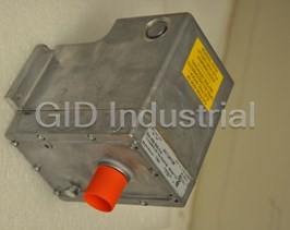
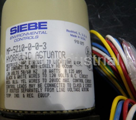
BARBER COLMAN-MP5210002-ACTUATOR
Part Number
MP5210002
Price
Request Quote
Manufacturer
BARBER COLMAN
Lead Time
Request Quote
Category
PRODUCTS - M
Specifications
Auxiliary Switch (-500 models)
10 Amps, 120/240 Vac adjustable SPDT, factory set to close the N.C. contact at the retracted end of stroke.
Compatible with
2 to 15 Vdc from TAC System 8000,TAC NETWORK 8000, or TAC DMS
Connections
Color-coded 4' (1.2 m) leads.
Damper
2" (51 mm) over a nominal 6 Vdc (fully retracted) to 9 Vdc (fully extended)
20 to 140°F (-29 to 60°C).
Humidity
5 to 95% RH, non-condensing.
Internal Power Supply
20 Vdc, 25 mA.
Location
NEMA Type 1.
Nominal Damper Area
Actuator selection should be made in accordance with damper
Nominal Extended Start Point
Approximately 6 Vdc.
Operating
-20 to 140°F (-29 to 60°C).
Operating Span
Nominally 3 Vdc fixed. 4.5 to 12 Vdc are required to assure full stroke
Power Input
Refer to Table-1 and Table-2. All 24 Vac circuits are Class 2.
Shipping & Storage
-40 to 160°F (-40 to 71°C).
Signal Impedance
10,000 O or greater.
Torque
Refer to Table-1 and Table-2.
Valve
9/16" (14.3 mm) over a nominal 6 Vdc (fully retracted) to 9 Vdc (fully extended)
Features
- 10,000 Oor greater input impedance.
- 24 Vac, 120 Vac, and 240 Vac models
- Available in damper models or base models that require damper or valve linkage.
- Die cast lower housing and painted steel upper housing.
- Fixed start point and non-positive positioning.
- Hydraulic actuator with oil-immersed motor, transducer, and pump.
- Internal feedback circuitry provides non-positive positioning control in relation to the controller signal.
- Linear motion output shaft controlled by a variable dc voltage input signal.
- Nominal 3 Vdc operating span.
- Optional adjustable SPDT auxiliary switch.
- Spring return.
Datasheet

Extracted Text
MP-5200 Series TAC 1354 Clifford Avenue P. O. Box 2940 Loves Park, IL 61132-2940 www.tac.com Electronic Hydraulic Actuator General Instructions Application The MP-5200 Series actuators are for the electronic proportional control of dampers, valves, or program switches which require the return to normal position upon power interruption. This series is compatible with TM 2 to 15 Vdc input signals from TAC System 8000 , ® TAC NETWORK 8000 , and TAC DMS DDC controllers. Features Linear motion output shaft controlled by a variable dc voltage input signal. MP-521X Spring return. Valve Actuator Nominal 3 Vdc operating span. Fixed start point and non-positive positioning. 10,000 Ω or greater input impedance. 24 Vac, 120 Vac, and 240 Vac models Optional adjustable SPDT auxiliary switch. Available in damper models or base models that require damper or valve linkage. Die cast lower housing and painted steel upper housing. Hydraulic actuator with oil-immersed motor, transducer, and pump. MP-523X Internal feedback circuitry provides non-positive Damper Actuator positioning control in relation to the controller signal. Applicable Literature TAC Cross-Reference Guide, F-23638 TAC Reference Manual, F-21683 Environmental Controls Application Manual, F-21335 TAC Electric/Electronic Products Catalog, F-27382 Engineering Bulletin EN-111, x Electronic Control, F-15264 AV-600 Hydraulic Actuator Valve Linkage Kit, F-26279 AV-601 Linkage Extension Set for AV-600 Valve Linkage Kit, F-26280 AV-7600-1 Hydraulic Actuator Valve Linkage Kit, F-26235 Printed in U.S.A. 8-06 © Copyright 2006 TAC All Rights Reserved. F-24789-6 SPECIFICATIONS Actuator Inputs Compatible with: 2 to 15 Vdc from TAC System 8000,TAC NETWORK 8000, or TAC DMS controllers. Operating Span, Nominally 3 Vdc fixed. 4.5 to 12 Vdc are required to assure full stroke travel under various loading conditions. Nominal Extended Start Point, Approximately 6 Vdc. Signal Impedance, 10,000 Ω or greater. Power Input: Refer to Table-1 and Table-2. All 24 Vac circuits are Class 2. Connections: Color-coded 4' (1.2 m) leads. Actuator Outputs Electrical: Internal Power Supply, 20 Vdc, 25 mA. Auxiliary Switch (-500 models), 10 Amps, 120/240 Vac adjustable SPDT, factory set to close the N.C. contact at the retracted end of stroke. Mechanical: Stroke, Damper 2" (51 mm) over a nominal 6 Vdc (fully retracted) to 9 Vdc (fully extended) input range (includes AM-601 linkage). Valve 9/16" (14.3 mm) over a nominal 6 Vdc (fully retracted) to 9 Vdc (fully extended) input range. Torque, Refer to Table-1 and Table-2. Nominal Damper Area: Actuator selection should be made in accordance with damper manufacturer’s specifications. Environment Ambient Temperature Limits: Shipping & Storage, -40 to 160° F (-40 to 71° C). Operating, -20 to 140° F (-29 to 60° C). Damper -20 to 140° F (-29 to 60° C). Valve Refer to Table-3. Humidity: 5 to 95% RH, non-condensing. Location: NEMA Type 1. Agency Listings UL 873: Underwriters Laboratories (File # E9429 Category Temperature-Indicating and Regulating Equipment). CSA: Certified for use in Canada by Underwriters Laboratories. Canadian Standard C22.2 No. 24-93. European Community: EMC Directive (89/336/EEC). Low Voltage Directive (72/23/EEC). Table-1 Model Chart for Damper Actuators. Actuator Power Input Timing in Seconds @ 72° F (22° C) a 10 Amps Torque Rating Part 60 Hz 50 Hz Aux No Load Stroke Retract (Extend & Retract) Voltage Number Switch on Power lb. - in. (N-m) ± 10% Watts Amps Watts Amps To Extend To Retract Loss MP-5230 120 11.7 0.16 12.9 0.19 No 60 40 15 1.86 (0.21) MP-5233 24 12.0 0.80 13.2 0.97 No a Common of switch is in series with AC power supply to the motor. Therefore, the switch must be wired to control the same voltage as the actuator itself. 2 Copyright 2006 TAC All Rights Reserved. F-24789-6 Table-2 Model Chart for Valve Actuators. Also for Damper Actuators with Field Assembled Damper Linkages. Timing in Seconds @ 72° F (22° Actuator Power Input Required Linkage C) 10 a Amps Part Number 60 Hz 50 HZ No Load Stroke Retract AC Aux on Voltage ± Damper Valve Switch To Power 10% Watts Amps Watts Amps To Retract Extend Loss MP-5210 No 120 11.7 0.16 12.9 0.19 MP-5210-500 Yes MP-5211 No AV-7600-1 b 240 11.8 0.08 13.0 0.09 60 40 15 AM-601 c AV-601 MP-5211-500 Yes MP-5213 No 24 12.0 0.80 13.2 0.97 MP-5213-500 Yes a Common of switch is in series with AC power supply to the motor. Therefore, the switch must be wired to control the same voltage as the actuator itself. b With the installation of the AM-601 damper linkage, these valve actuators become functionally the same as the damper actuators listed in Table-1. Refer to Table-1 for the torque rating. c AV-601 required for steam applications, recommended for hot water applications and in chilled water applications where condensation may occur on actuator. Table-3 Maximum Allowable Ambient Air Temperature for Valve Actuators. Maximum Allowable Ambient Air Temperature Temperature of Media of MP-52xx Series in the Valve Body (Check the Rating of the Valve) AV-600 Only for Chilled AV-600 with AV-601 extension °F (°C) Water Applications °F (°C) °F (°C) 366 (180) 90 (32) 90 (32) 340 (171) 100 (38) 100 (38) 281 (138) 115 (46) 140 (60) 181 (83) 140 (60) 140 (60) 80 (26) 140 (60) 140 (60) ACCESSORIES Common 11-1612 1/2" conduit bushing. AD-8969-612 Capacitor kit For MP-52xx-xxx-0-3 and earlier models only. Capacitor built into MP- 52xx-xxx-0-4 and later models. Damper Only AD-553 Sequencing adaptor. AE-249 Transformer. AM-111 Crank arm for 5/16" diameter damper shaft. AM-112 Crank arm for 3/8" diameter damper shaft. AM-113 Crank arm for 1/2" diameter damper shaft. AM-115 Crank arm for 7/16" diameter damper shaft. AM-122 Linkage connector straight type. AM-123 Damper clip. AM-125 5/16" diameter x 20" damper rod. AM-125-048 5/16" diameter x 48" damper rod. AM-132 Ball joint connector. AM-161-3 Damper linkage kit. AM-601 Device includes mounting bracket, damper linkage with spring, and AM-122 straight connector. Required to modify (MP-521x series) valve actuators into 2" (51 mm) stroke damper actuators. AM-602 Spacer. Valve Only AV-600 Valve linkage. AV-601 Valve linkage extension for hot water and steam applications; use with AV-600 (may be used on chilled water to avoid condensation). TOOLS (factory available) TOOL-12 Wrench for adjustment of auxiliary switch. TOOL-19 Spring compression tool for AV-600. TOOL-37 1-5/8" open-end wrench. TOOL-202 Manual positioner. F-24789-6 © Copyright 2006 TAC All Rights Reserved. 3 TYPICAL APPLICATIONS (wiring diagrams) Vac Power Black 24 Vac Black/Blue 120 Vac White 240 Vac White/Black Typical Controllers CP-8102 Red (+20) Red TP-810X Yellow (OP1) Yellow TP-8121 Blue (COM) TP-8124 Blue TP-8232 Green Maximum of 2 MP-52XX MP-52XX-500 models Vac Power include internal SPDT auxiliary switch. Red Yellow Blue N.C. Orange Green COM (wired internally to Brown black power lead) N.O. MP-52XX Figure-1 Typical Control Wiring for Up to Two MP-5200 Series Actuators to Controllers Requiring External 20 Vdc Power Supply. 4 Copyright 2006 TAC All Rights Reserved. F-24789-6 Vac Power Black 24 Vac Black/Blue 120 Vac White Typical Controllers 240 Vac White/Black CP-8102 Red (+20) Red TP-810X TP-8121 Yellow (OP1) Yellow TP-8124 Blue (COM) Blue TP-8232 Green Maximum of 2 MP-52XX MP-52XX-500 models Vac Power include internal SPDT auxiliary switch. Red N.C. Orange Yellow COM (wired internally to Brown Blue black power lead) N.O. Green MP-52XX Vac Power To 4 additional Actuators Yellow Blue 1 Capacitor AD-8969-612 must Blue be connected between Red and Red Red Blue leads (max. 4) MP-52XX. Required only for MP-52XX-XXX-0-3 Green and earlier models. Capacitor built into MP-52XX MP-52XX-XXX-0-4 and later models. 1 Max. of 4 additional MP-52XX. Each requires one AD-8969-612 filter. Figure-2 Typical Control Wiring for More Than Two MP-5200 Series Actuators to Controller Requiring External 20 Vdc Power from the Actuator. F-24789-6 © Copyright 2006 TAC All Rights Reserved. 5 Max. of 5 additional 1 MP-52XX. Each requires one AD-8969-612 filter. Vac Power Typical Controllers Black CC-8111 Yellow 24 Vac Black/Blue OP1 CC-8118 120 Vac White COM Blue CC-8218 240 Vac White/Black CP-8161 CP-8261 Yellow To Controller Blue Blue Typical DDC Controllers Red Red Yellow AO COM Blue Green MICROZONE® II LCM™ MP-52XX DMS SH Capacitor AD-8969-612 must be connected between Red and MP-52XX-500 models 1 Blue leads (max. 4) MP-52XX. include internal SPDT Note 1: When applied with most DDC auxiliary switch. controllers, the actuator’s 20 Vdc supply (red to blue) is not Vac Power required. In such a case, each actuator requires the installation of one AD-8969-612 capacitor kit N.C. Orange (filter) between its +20 Vdc (red) COM and COM (blue) leads. Brown Yellow (wired internally to Note 2: When this actuator is used with a Blue N.O. black power lead) DDC controller, it is important to Blue program the controller's output to provide a minimum control span Red Red of 4.5 to 11.5 Vdc, to assure full To 4 Green travel to each end of the actuator additional MP-52XX stroke. Actuators 1 Required only for MP-52XX-XXX-0-3 and earlier models. Capacitor built into MP-52XX-XXX-0-4 and later models. Figure-3 Typical Control Wiring For Up to Six MP-5200 Series Actuators to Controllers That Do Not Require 20 Vdc Power From the Actuator. 6 Copyright 2006 TAC All Rights Reserved. F-24789-6 24 Vac Black/Blue To Vac Power 120 Vac White 240 Vac White/Black Black Green MP-52XX Green MP-52XX To additional MP-52XX Series Actuator Figure-4 Wiring of Multiple MP-5200 Series Actuators to Single Power Source. INSTALLATION Inspection Inspect the package for damage. If damaged, notify the appropriate carrier immediately. If undamaged, open the package and inspect the device for obvious damage. Return damaged products. RequirementsJob wiring diagrams Tools (not provided): – Digital Volt-ohm Meter (DVM) – Appropriate drill and drill bit for mounting screws on dampers – Appropriate screw drivers and wrenches – TOOL-12, Wrench for adjustment of auxiliary switch – TOOL-19, Spring compression tool for AV-600 when used on VB-9xxx valves only – TOOL-37, 1-5/8" open-ended wrench Training: Installer must be a qualified, experienced technician Warning: Disconnect power at breaker or fuse before installation to prevent electrical shock and equipment damage. Make all connections in accordance with the wiring diagram and in accordance with national and local electrical codes. Use copper conductors only. F-24789-6 © Copyright 2006 TAC All Rights Reserved. 7 Caution: Static charges produce voltages high enough to damage the electronic components. Follow static electricity precautions when installing or servicing the device(s). Discharge any static electricity you may have accumulated by using wrist straps, or by touching a known, securely grounded object. Do not exceed the ratings of the device(s). Do not apply power to the unit unless the damper linkage and/or the valve assembly have been installed. Avoid locations where excessive moisture, corrosive fumes, or vibration is present. Do not install insulation on any part of the actuator. Mounting Caution: Do not twist or exert any force on the actuator housing during installation. Either turn the base by hand or, if necessary, use a 1-5/8" open-ended wrench (TOOL-37) on the flats provided on the actuator base or the valve body mounting nut. Refer to Figure-5. Housing Base Position Indicator Wrench Flats Figure-5 Housing and Base Location. Dampers The actuator is not position sensitive. It can be mounted in any position in a NEMA Type 1 location. Valves Allow 3" (76 mm) of clearance above the actuator valve assembly for the removal and reattachment of the actuator to the installed valve. 1. Install all two-way valves so that they close against the flow. An arrow on the valve body or tag indicates proper flow direction. 2. Always install three-way mixing valves with two inlets and one outlet. 3. Always install three-way diverting valves with one inlet and two outlets. 4. Actuators can be mounted in any upright position to approximately 5° above the centerline of the valve body. Caution: For steam applications only, mount the actuator above the valve body at approximately 45° from vertical for maximum heat dissipation. 8 Copyright 2006 TAC All Rights Reserved. F-24789-6 Wiring Requirements Control Leads The control leads may be connected to a Class 2 circuit if routed separately from Class 1 circuit wiring. Refer to Figure-9. Refer to Table-4 for the maximum wire run of the control leads. Caution: Use three-conductor, twisted, shielded wire when it becomes necessary to install the control leads in the same conduit with power wiring or when RFI/EMI generating devices are near. Do not connect the shield or conduit to earth ground. Table-4 Control Wiring Data. Wire Size Maximum Wire Run GA ft. (m) 18 1000 (304.8) 16 2250 (685.8) 14 4000 (1219.1) Power Leads The low voltage (24 Vac) power leads may be connected to a Class 2 circuit if routed separately from Class 1 circuit wiring. Refer to Figure-9. Line voltage power leads must be connected to a Class 1 circuit. Refer to Table-5 for maximum length of run for given wire size(s). To determine the allowable maximum power lead run for multiple actuator wiring, divide the maximum run shown in Table-5 by the number of actuators on the run. Table-5 Power Wiring Data. Actuator Actuator Model Power Lead Wire Size Maximum Wire Run Voltage Number Colors GA ft. (m) Vac MP-52x0 3500 120 Black & White (1067) MP-5210-500 MP-52x1 6000 240 Black & White/Black 14 (1829) MP-5211-500 MP-52x3 300 24 Black & Black/Blue (91.5) MP-5213-500 MP-52x3 480 24 Black & Black/Blue 12 (146.3) MP-5213-500 F-24789-6 © Copyright 2006 TAC All Rights Reserved. 9 Wiring Connections Wire Lead Connections (No Conduit) Make connections as required. Refer to Figure-6. Note: Cover plate and screw supplied with actuator are not required with this method. Figure-6 Wire Leads Connection (No Conduit). Installing 3/8" Flexible Conduit onto One or Both Sides of Actuator Flexible conduit may be installed onto one or both sides of the actuator (refer to Figure-8 and Figure-9). Install each conduit as follows: 1. Determine the side of the actuator to which the flexible conduit is to be attached. 2. Remove the knockout, using channel lock pliers, on the selected side of the actuator. Refer to Figure-7. 3. Make the required connections. Refer to Figure-1, Figure-2, or Figure-3 for a wiring diagram similar to your particular application. Base Knockout Figure-7 Removal of Knockout on Actuator Base. 4. Slip the conduit onto the base, over the ribs. Refer to Figure-8 and Figure-9. 10 Copyright 2006 TAC All Rights Reserved. F-24789-6 Base Cover Plate Ribs or Figure-8 Flexible Conduit Installation to Either Side of Actuator. Line voltage motor or auxiliary switch Typical for 24 Vac leads only when connected to other models (MP-52X3) than Class 2 circuits. 4 x 4 Conduit Box Transformer (AM-610 shown) Cover Plate Leave Knockout in place Low voltage motor or control leads Note: Class 2 circuit wiring must be routed may be connected to a Class 2 separately from the wiring from other circuits. circuit if routed separately from Do not route Class 2 circuit wiring in the same line voltage circuit wiring. conduit box with the line voltage transformer. Figure-9 MP-5200 Series Wiring with Separation for Line Voltage and Class 2 Circuits. 5. Install the cover plate with two screws. The cover plate and two screws are supplied with the actuator. 6. If flexible conduit is to be installed on both sides of the actuator, repeat the preceding steps to install the second conduit. Auxiliary Switch Leads The low voltage (24 Vac) auxiliary switch leads may be connected to a Class 2 circuit. The line voltage (120 Vac and 240 Vac) auxiliary switch leads must be connected to a Class 1 circuit and routed separately from any Class 2 circuit wiring. Refer to Figure-4. F-24789-6 © Copyright 2006 TAC All Rights Reserved. 11 Installing Conduit Box Onto Actuator Installation of a conduit box allows for the attachment of one or more thin wall conduits to the actuator. This procedure also serves as an optional method for connecting flexible conduit to the actuator. 1. Remove the knockout from the cover plate supplied with the actuator. Refer to Figure-10. Cover Plate Knockout Figure-10 Cover Plate Knockout Removal. 2. Slip the actuator’s leads through a standard 1/2” conduit bushing (Figure-11, not supplied) and the knockout hole in the cover plate. Refer to Figure-12. 1/8" (3 mm) maximum Use TAC 11-1612, Bridgeport 1102-DC, or equivalent Figure-11 1/2" Conduit Bushing. 1/2" Conduit Bushing Base (not supplied) Cover Plate Figure-12 Conduit Bushing and Cover Plate Installation. 3. Seat the conduit bushing in the base. 4. Install the cover plate, using the two screws provided. 5. Loosely install the conduit box and the locknut onto the conduit bushing. Refer to Figure-13. 12 Copyright 2006 TAC All Rights Reserved. F-24789-6 Conduit Lock Nut Figure-13 Attachment of Conduit Box to Conduit Bushing. 6. Tighten the locknut as follows: a. Tilt the conduit box approximately 30 degrees counterclockwise, relative to the actuator. b. Finger-tighten the locknut against the conduit box. c. Rotate the conduit box clockwise until it is aligned with the actuator. This will tighten the locknut. 7. Make the required wiring connections. Refer to Figure-1, Figure-2, and Figure-3 for typical control wiring diagrams. 8. Install the conduit to the conduit box as required. Note: As shown in Figure-12, the hole in the actuator’s cover plate is also sized to accept both British standard M20 (20 mm) conduit connectors and 20 mm-to-PG16 adaptors for use with DIN PG16 connectors. (Follow the steps for installing the conduit box to the actuator.) Linkage Assembly Damper Note: Each actuator in the MP-523x Series is provided with a factory-installed damper linkage. No separately-ordered linkage is required. Do not twist or exert any force on the actuator housing during installation. Either turn the base by hand or, if necessary, use a 1-5/8" open-ended wrench (TOOL-37) on the flats provided on the actuator base, or on the valve body mounting nut. Refer to Figure-5. 1. Determine the best mounting position for the actuator as follows: a. Determine, from the system requirements, if the damper should spring-return to the open position (Figure-14) or closed position (Figure-15) whenever power is lost to the actuator. For example, an outside air damper actuator is typically linked so as to retract (spring-return) to the damper’s fully closed position (safe position). b. Be sure to allow adequate working space around the actuator mounting location to mount the actuator, link it to the damper, and wire it into the system (refer to Figure-21). c. If possible, select a mounting position such that, at mid-stroke, the actuator crank arm and the damper crank arm on the drive shaft are each at a 90° angle to the damper rod (refer to Figure-16). This is the recommended mounting position. It may be necessary to swivel the actuator linkage to arrive at this mounting location. d. Consider the damper rod length when positioning the actuator in relation to the damper. A damper rod that is too long is not rigid enough to provide good control, while a damper rod that is too short makes adjustment difficult. F-24789-6 © Copyright 2006 TAC All Rights Reserved. 13 Spring returns open on loss of power Open Close Retract Extend Damper Shaft Figure-14 Dampers Open When Actuator Retracts (Spring-Returns Open on Power Loss). Spring returns closed on loss of power Extend Retract Open Close Damper Shaft Figure-15 Dampers Open When Actuator Extends (Spring-Returns Closed on Power Loss). 2. Position the actuator on the duct and mark the location of the mounting holes, using the actuator mounting bracket as a template (refer to Figure-21). 3. Drill or punch the mounting holes in the duct for the appropriate 1/4" (6 mm) diameter screws or bolts. The actuator must be mounted firmly enough to prevent excessive actuator movement under normal damper loading. If there is excessive actuator movement, the damper may not fully open or close. Mid-Stroke Position Mounting Actuator Angle from Mid-Stroke Points Crank Arm Position (See Table) Angle Position of Required from Linkage Damper Mid-Stroke Connector Rotation Position 60 30 2" (50 mm) 90 45 1-1/2" (38 mm) Mounting Points Damper Rod Linkage Position of Linkage Connectors Connector (See Table) Damper Damper Crank Arm Shaft Figure-16 Actuator/Damper Mounting. 4. Mount a ball joint connector in the slot on the damper crank arm. To achieve 90° of damper rotation, position the connector 1-1/2" (38 mm) from the centerline of the shaft hole on the crank arm. For 60° of damper rotation, position the connector 2" (50 mm) from the shaft hole centerline. Typically, 60° to 70° of rotation (maximum is 90°) is sufficient to permit almost maximum air flow through the dampers. Refer to Figure-16. 14 Copyright 2006 TAC All Rights Reserved. F-24789-6 5. Rotate the damper to its open position. Install and secure the damper crank arm (with ball joint connector) to the damper shaft, positioning the crank arm as follows (refer to Figure-16): a. To achieve 60° of damper rotation, position the crank arm so that it is pointed towards the actuator at 30° from its mid-stroke position. b. To achieve 90° of damper rotation, position the crank arm so that it is pointed towards the actuator at 45° from its mid-stroke position. 6. Install the damper rod by sliding one end through the ball joint connector mounted on the damper crank arm, and the other end through the straight connector on the actuator crank arm. Tighten the nut on the actuator crank arm’s straight connector. Cut off any excess length of damper rod. 7. For normally open dampers, tighten the nut on the ball joint connector on the damper crank arm. To ensure that the damper closes completely, make adjustments so that the actuator is 1/16" (1.6 mm) from the extended end of stroke when the damper closes. Verify and, if necessary, make final adjustments during system checkout. 8. For normally closed dampers, rotate the damper crank arm until the damper is closed. While holding the damper closed, tighten the nut on the ball joint connector on the damper crank arm. To ensure that the damper closes completely, make adjustments so that the actuator is 1/16" (1.6 mm) from the retracted end of stroke when the damper closes. Final adjustment of the actuator and damper must be performed when the system is powered and functioning. Refer to the CHECKOUT section to ensure that the damper is linked correctly. Valve For valve assembly details refer to AV-600, Valve Linkage Kit General Instructions, F-26279 for VB-9xxx valves, or AV-7600-1, Valve Linkage Kit General Instructions, F-26235 for VB-7xxx valves, with AV-601, Linkage Extension Kit General Instructions, F-26280. Refer to Figure-22 for external dimensions of the valve actuator. Adjustments Auxiliary Switch (MP-52xx-500) The switching point is adjustable over the entire actuator stroke and is pre-set at the factory to close the N.C. contacts at the retracted end of stroke. Turning the switch adjustment screw CW (using TOOL-12), adjusts the make (or break) point closer to the extended end of stroke. Refer to Figure-17. MP-52XX-500 Series Auxiliary Switch Adjustment Screw Position Indication and Switch Action Cam Figure-17 Auxiliary Switch Point Adjustment and Position Indication for MP-5200 Series. F-24789-6 © Copyright 2006 TAC All Rights Reserved. 15 CHECKOUT After the entire system has been installed and the actuator has been powered up, perform the following checks for proper system operation. Caution: Never power the actuator without a spring return linkage attached. Go, No-Go Test 1. If actuator is MP-52xx-xxx-0-3 or older model, install the AD-8969-612 filter capacitor (not required for MP-52xx-xxx-0-4 or newer models). 2. The actuator should be powered. 3. Disconnect the control leads from the controller. 4. To make the actuator shaft extend fully, short the red lead to the yellow lead. 5. To make the actuator retract fully, short the blue lead to the yellow lead. 6. Check for proper operation of the valve or damper as the actuator is operated. 7. Reconnect the control wiring. Positioning with If the sensed media is within the controller’s setpoint range, the actuator can be positioned by adjusting the controller setpoint up and down. Check for correct operation of the actuator Controller (valve or damper) while the actuator is being stroked. THEORY OF OPERATION Refer to Figure-18. The permanently sealed, oil-filled case contains a movable hydraulic piston assembly and an electric pump/motor for the hydraulic system. The electric pump/motor is powered by the input supply voltage and runs continuously, generating a fluid pressure which is transmitted to the top of the piston. This fluid pressure creates a hydraulic force which drives the piston downward. Opposing the hydraulic force is the spring of the valve or damper linkage. When the hydraulic force becomes great enough to overcome the opposing spring force, the piston translates downward, extending the output shaft. The pump/motor contains a transformer winding which provides power to the Vdc power supply. The power supply, in turn, provides power to the transducer assembly. To proportionally position the shaft, first the control signal (2 to 15 Vdc) input is compared to the shaft position feedback signal, through the actuator controller circuit. Then, the actuator controller circuit emits an output signal which positions the flapper in the transducer. The flapper opens or closes further to decrease or increase the hydraulic pressure above the piston, resulting in an upward or downward movement at the shaft. Oil-Filled Case Hydraulic Piston Assembly Transducer Assembly Vdc Power Supply Electric Motor/Pump To AC Power Source Feedback Yellow (+) Controller Printed Circuit Board Controller Input Blue (-) Figure-18 MP-5200 Series Actuators. 16 Copyright 2006 TAC All Rights Reserved. F-24789-6 REPLACEMENT PARTS The installation of replacement actuators, in place of the obsolete series of MP-52xx actuators, may require additional items. These replacement items are required for the following reasons: 1. The AM-601 damper linkage is used to convert base actuators to damper actuators when damper models are not available. Refer to Figure-20. 2. The AM-602 spacer is used when current actuators are installed on old linkages. Refer to Figure-19. 3. The AE-249 transformer (208 Vac to 120 Vac) is used when replacing 208 Vac actuators with 120 Vac actuators. 4. Resistors are required when an obsolete TP-5xxx or CP-51xx controller is used to control a current actuator. Detailed resistor and wiring information is provided in section C1.1 of Engineering Bulletin EN-111 (TAC System 8000 Electronic Control), F-15264. 2-3/16" 1-5/8" (56mm approx.) (41mm approx.) Spacer AM-602 1-5/8" (41mm approx.) Obsolete Linkages Current Linkage Figure-19 Current or Obsolete Valve Linkage. No Strap Strap Current AM-601-0-0-2 Obsolete AM-601 Figure-20 Current or Obsolete Damper Linkage. F-24789-6 © Copyright 2006 TAC All Rights Reserved. 17 Table-6 Cross Reference of Obsolete Series of MP-5200 Actuators. Other Replacement Items Required Actuator Replacement AM-601-0-0-2 a Being AM-602 AE-249 b Actuator Current Damper Resistor Replaced Spacer Transformer Linkage MP-5210 MP-5210-0-0-3 No Yes No Yes MP-5210-0-0-1 MP-5210-0-0-3 No Yes No Yes MP-5210-0-0-2 MP-5210-0-0-3 No No No No MP-5210-500 MP-5210-500-0-3 No Yes No Yes MP-5210-500-0-1 MP-5210-500-0-3 No Yes No No MP-5210-500-0-2 MP-5210-500-0-3 No No No No MP-5211 MP-5211-0-0-3 No Yes No Yes MP-5211-0-0-1 MP-5211-0-0-3 No Yes No No MP-5211-0-0-2 MP-5211-0-0-3 No No No No MP-5211-500 MP-5211-500-0-3 No Yes No Yes MP-5211-500-0-1 MP-5211-500-0-3 No Yes No No MP-5211-500-0-2 MP-5211-500-0-3 No No No No MP-5212 MP-5210-0-0-3 No Yes Yes Yes MP-5212-0-0-1 MP-5210-0-0-3 No Yes Yes No MP-5212-0-0-2 MP-5210-0-0-3 No No Yes No MP-5212-500 MP-5210-500-0-3 No Yes Yes Yes MP-5212-500-0-1 MP-5210-500-0-3 No Yes Yes No MP-5212-500-0-2 MP-5210-500-0-3 No No Yes No MP-5213 MP-5213-0-0-3 No Yes No Yes MP-5213-0-0-1 MP-5213-0-0-3 No Yes No No MP-5213-0-0-2 MP-5213-0-0-3 No No No No MP-5213-500 MP-5213-500-0-3 No Yes No Yes MP-5213-500-0-1 MP-5213-500-0-3 No Yes No No MP-5213-500-0-2 MP-5213-500-0-3 No No No No MP-5220 MP-5230-0-0-3 No No No Yes MP-5220-0-0-1 MP-5230-0-0-3 No No No No MP-5220-500 MP-5230-0-0-3 Yes No No Yes MP-5220-500-0-1 MP-5230-500-0-3 Yes No No No MP-5221 MP-5211-0-0-3 Yes No No No MP-5221-0-0-1 MP-5211-0-0-3 Yes No No No MP-5221-500 MP-5211-500-0-3 Yes No No Yes MP-5221-500-0-1 MP-5211-500-0-3 Yes No No No MP-5222 MP-5230-0-0-3 No No Yes Yes MP-5222-0-0-1 MP-5230-0-0-3 No No Yes No MP-5222-500 MP-5320-0-0-3 Yes No Yes Yes MP-5222-500-0-1 MP-5230-0-0-3 Yes No Yes No MP-5223 MP-5233-0-0-3 No No No Yes MP-5223-0-0-1 MP-5233-0-0-3 No No No No MP-5223-500 MP-5230-0-0-3 Yes No No Yes MP-5223-500-0-1 MP-5233-0-0-3 Yes No No No MP-5230 MP-5230-0-0-3 No No No No MP-5230-500 MP-5230-0-0-3 Yes No No No MP-5231 MP-5211-0-0-3 Yes No No No MP-5231-500 MP-5230-0-0-3 Yes No No No MP-5232 MP-5230-0-0-3 No No Yes No MP-5232-500 MP-5230-0-0-3 Yes No Yes No MP-5233 MP-5233-0-0-3 No No No No MP-5233-500 MP-5233-500-0-3 No No No No a AE-249 is 208 Vac to 120 Vac Transformer. b Refer to Engineering Bulletin EN-111 section C1.1 for resistor value and wiring information. 18 Copyright 2006 TAC All Rights Reserved. F-24789-6 MAINTENANCE The actuator is sealed in oil and requires no maintenance. Regular maintenance of the total system is recommended to assure sustained, optimum performance. TROUBLESHOOTING Use the following steps to locate malfunctions: 1. Disconnect control wiring. 2. Check for the proper supply voltage to the actuator. 3. The motor should run when power is applied. If it does not run, the actuator is inoperative and should be replaced. 4. With the actuator motor running: a. Short the red lead to the yellow lead and observe the position indicator shown in Figure-5. The actuator should extend. b. Short the blue lead to the Yellow lead, this should cause the indicator to retract. c. If the actuator is installed on a damper check the linkage for any damage or misadjustment which could prevent the actuator from extending. If the mechanical linkage is inoperative, adjust the linkage or replace the damaged components, as applicable. If the mechanical linkage moves correctly and freely, the problem lies in the actuator and it must be replaced. 5. Reconnect control wiring. 6. If applying power directly to the actuator results in correct operation of the actuator, the actuator and linkage are functional, and the problem lies with the control signal. Repair or replace the controller, wiring, or thermostat, as applicable. FIELD REPAIR None. Replace an inoperative actuator with a functional unit. F-24789-6 © Copyright 2006 TAC All Rights Reserved. 19 DIMENSIONAL DATA (4) 1/4" 5/16" 4-5/8" (6 mm) (8 mm) (117 mm) 4-3/4" (120 mm) 3-1/4" 4-1/4" Actuator (108 mm) (83 mm) 5-3/4" 4-1/4" (146 mm) (110 mm) 8" 2" 5-1/2" (203 mm) (50 mm) (140 mm) Figure-21 Damper Linkage Assembly Dimensions. 3-1/4" Dia. 3-23/32" (83 mm) (94 mm) 6-3/4" (171 mm) 1-3/8" (35 mm) 2-9/32" (58 mm) Figure-22 Actuator Dimensions. Copyright 2006, TAC TAC All brand names, trademarks and registered 1354 Clifford Avenue trademarks are the property of their respective P.O. Box 2940 owners. Information contained within this Loves Park, IL 61132-2940 document is subject to change without notice. F-24789-6 www.tac.com
Frequently asked questions
What makes Elite.Parts unique?

What kind of warranty will the MP5210002 have?
Which carriers does Elite.Parts work with?
Will Elite.Parts sell to me even though I live outside the USA?
I have a preferred payment method. Will Elite.Parts accept it?
Why buy from GID?

Quality
We are industry veterans who take pride in our work

Protection
Avoid the dangers of risky trading in the gray market

Access
Our network of suppliers is ready and at your disposal

Savings
Maintain legacy systems to prevent costly downtime

Speed
Time is of the essence, and we are respectful of yours
Related Products

Barber Colman MA-405-0-0-2 120 Volt Actuator Motor 2 Position

Barber Colman MA-405-0-0-4 Actuater, 120 Volts, 60HZ, 25 Watts
TWO POSITION ACTUATOR WITH AUXILIARY SWITCH, 120V/60HZ
Barber Colman MF2-PID Controller - MICROFLO II VAV CONTROLLER
Barber Colman MM-500-0-0-1 Motor - MODULAR MOTOR 24VAC 50/60HZ 20VA SPRING RETURN
Barber Colman MP5210003 Actuator - 10WATT 50/60HZ
Request a Quote

The quote request has been received
Close

Facing challenges or have inquiries? Feel free to contact us!
Call Us +1-469-283-2440
What they say about us
FANTASTIC RESOURCE
One of our top priorities is maintaining our business with precision, and we are constantly looking for affiliates that can help us achieve our goal. With the aid of GID Industrial, our obsolete product management has never been more efficient. They have been a great resource to our company, and have quickly become a go-to supplier on our list!
Bucher Emhart Glass
EXCELLENT SERVICE
With our strict fundamentals and high expectations, we were surprised when we came across GID Industrial and their competitive pricing. When we approached them with our issue, they were incredibly confident in being able to provide us with a seamless solution at the best price for us. GID Industrial quickly understood our needs and provided us with excellent service, as well as fully tested product to ensure what we received would be the right fit for our company.
Fuji
HARD TO FIND A BETTER PROVIDER
Our company provides services to aid in the manufacture of technological products, such as semiconductors and flat panel displays, and often searching for distributors of obsolete product we require can waste time and money. Finding GID Industrial proved to be a great asset to our company, with cost effective solutions and superior knowledge on all of their materials, it’d be hard to find a better provider of obsolete or hard to find products.
Applied Materials
CONSISTENTLY DELIVERS QUALITY SOLUTIONS
Over the years, the equipment used in our company becomes discontinued, but they’re still of great use to us and our customers. Once these products are no longer available through the manufacturer, finding a reliable, quick supplier is a necessity, and luckily for us, GID Industrial has provided the most trustworthy, quality solutions to our obsolete component needs.
Nidec Vamco
TERRIFIC RESOURCE
This company has been a terrific help to us (I work for Trican Well Service) in sourcing the Micron Ram Memory we needed for our Siemens computers. Great service! And great pricing! I know when the product is shipping and when it will arrive, all the way through the ordering process.
Trican Well Service
GO TO SOURCE
When I can't find an obsolete part, I first call GID and they'll come up with my parts every time. Great customer service and follow up as well. Scott emails me from time to time to touch base and see if we're having trouble finding something.....which is often with our 25 yr old equipment.
ConAgra Foods