

 Manufacturers
BARBER COLMAN MP-475-0-2-2

Description
Barber Colman MP-475-0-2-2 Reversible and Proportional Electric Actuator
Part Number
MP-475-0-2-2
Price
Request Quote
Manufacturer
BARBER COLMAN
Lead Time
Request Quote
Category
PRODUCTS - M
Datasheet

Extracted Text
MP-3xx Series, MP-4xx Series, MP-2xxx Series, and MP-4xxx Series Reversible and Proportional Electric Actuators General Instructions Application The MP series actuators are used for two-position, floating, and proportional control of dampers, valves, and program switches in heating, ventilating, air conditioning, and similar applications. Hazardous location models offer a sturdy cast aluminum case with bolted cover. They have two 3/4" pipe tapped openings for joints with rigid metal conduit. All wiring is brought out to separate terminals for ease Typical Spring Return of installation. These factory enclosure and actuator assemblies are Underwriters Laboratories Listed. Features • Proportional actuators with built-in feedback potentiometers • Spring return and non-spring return models Typical Non-Spring Return available • 24 Vac, 120 Vac, and 240 Vac models are available • Actuator has a rugged die cast aluminum housing with two 1/2” conduit openings. • Hazardous location actuator housing has two 3/4" pipe taped openings for rigid metal conduit connection • Oil-immersed motor and gear train Applicable Literature Typical -6xx Suffix • Valve Selection Guide, F-26094 (CP-8301-xxx or CP-8391-91x Installed) • AV-29x Valve Linkage for Hazardous Location Gear Train Actuators General Instructions, F-27441. • Apparatus for Hazardous Locations EN-56-2, F-18451. • AV-390 Series, Valve Linkage for Gear Train Actuators, General Instructions, F-24376 • Material Safety Data Sheet MSDS-4 • AM-363 Gasket Cover Kit General Instructions, F-25598 • CP-8301 Solid State Actuator Drive General Typical MP6 Instructions, F-14940 (Hazardous Locations) • CP-8391-716 Electronic Actuator Drive General Instructions, F-21220 * Refer to Table-5 to identify specific models that are in • CP-8391-910 Series 4 to 20 mA Electronic Actuator compliance with CE requirements. Drive General Instructions, F-22453 • AE-504 Solid State Paralleling Relay General Instructions, F-16524 Printed in U.S.A. 3/11 © Copyright 2011 Schneider Electric All Rights Reserved. F-15479-11 SPECIFICATIONS Actuator Inputs Input Control Signals: Refer to the actuator selection tables beginning on page 3 for input control signal capability versus specific actuator models. Floating, Requires one Single Pole Double Throw (SPDT) switch with floating (center off) position rated at 0.9 amps @ 24 Vac or two Single Pole Single Throw (SPST) switches rated at 0.9 amps @ 24 Vac. Two-Position, SPDT Requires snap acting switch rated at 0.9 amps @ 24 Vac. SPST Can be used with certain spring return actuators. Switch must be rated to handle actuator power requirements. Barber-Colman Microtherm, Proportional Electrical system with the following typical controllers: PP-22x series, TP-1xx series, TP-2xx series, TP-3xx series, TP-4xx series, TP-1xxx series, and TP-1xxxx series. Standard Control of a single actuator. Sequencing Control of two actuators in sequence. Five-Position Used typically for adjustable minimum position (five positions) of an economizer actuator. Slidewire and Paralleling, Requires AE-504 paralleling relay. Refer to AE-504 Solid State Paralleling Relay General Instructions F-16524. AE-504 accepts 100 Ω to 1000 Ω slidewires. Voltage Vdc, Requires CP-8301-xxx series of solid state actuator drives. Refer to CP-8301 Solid State Actuator Drive General Instructions F-14940. Refer to the actuator selection tables beginning on page 3. Current mAdc, Requires CP-8391-xxx series of solid state actuator drives. Refer to the actuator selection tables beginning on page 3. Power Requirements: Refer to the actuator selection tables beginning on page 3 to determine power requirements. Connections: MP-3xx, 4xx, 2xxx, 4xxx, Coded screw terminals. Models with “-600” Suffix, Coded screw terminals except for input signal which are color coded pigtails. Actuator Outputs Torque: Refer to the actuator selection tables beginning on page 3 to determine the actuator torque rating. Nominal Damper Area: Actuator selection should be made in accordance with the damper manufacturer’s specifications. Stroke (Degrees of Rotation), Refer to the actuator selection tables beginning on page 3 for information on degrees of rotation. Auxiliary Switch, Refer to the actuator selection tables beginning on page 3 for the models that include an auxiliary switch. Refer to Table-7 for ratings. Spring Return: Refer to the actuator selection tables beginning on page 3 for models that are spring return. Environment Ambient Temperature Limits: Shipping and Storage, -40 to 160 °F (-40 to 71 °C). Operating, -40 to 136 °F (-40 to 58 °C). Humidity: 5 to 95% RH, non-condensing. Locations: NEMA 1 NEMA 4 for non-spring return actuators with AM-363. Agency Listings: US Standard UL 873, Underwriters Laboratories (File #E9429 XAPX, Temperature Indicating and Regulating Equipment). Canadian Standard C22.2 No. 24: Underwriters Laboratories (File #E429 Category XAPX7, Temperature Indicating and Regulating Equipment). European Community, EMC Directive (2004/108/EC). Low Voltage Directive (2006/95/EC). Refer to Table-5 to identify specific models that are in compliance with CE requirements. Hazardous Location Models, UL file #29291. Designed for use in hazardous locations N.E.C., Class 1, Groups C and D, and Class 2, Groups E, F, and G. Temperature code T6 for hazardous housing. 2 © Copyright 2011 Schneider Electric All Rights Reserved. F-15479-11 F-15479-11 © Copyright 2011 Schneider Electric All Rights Reserved. 3 Actuators in the actuator selection tables below with “-600” suffix have the CP-8301-120 factory installed. All CP-8301s have a fixed span of 3 Vdc to drive the actuator full stroke and a start point adjustable from 2 to 12 Vdc (factory set 6 Vdc). The CP-8391-91x series have a fixed range of 4 to 20 mAdc to drive the actuator full stroke. Refer to CP-8391-910 Series 4 to 20 mA Electronic Actuator Drive General Instructions F-22453. The CP-8391-716 has an adjustable span of 4 to 16 mAdc (factory set for 16) and adjustable start point of 2 to 16 mAdc (factory set for 4). The input signal on CP-8391-716 is optically isolated. Refer to CP-8391-716 Electronic Actuator Drive General Instructions F-21220. Table-1 MP-2xxx Series Model Chart. Input Control Signal External Wiring (and required Interface Module that must be purchased separately) Power Requirements Output Shaft (See Figure) Internal a Actuator Barber-Colman Microtherm Built-in Wiring Aux. 2-Position 2-Position Part (Proportional Electric) Trans- 135 to Torque Timing (See Switch b SPST or Degrees of Spring Number former 1,000 Ω Voltage Vdc Current mAdc Volts Hz. Amps Lb.-in. Seconds Figure) Sequencing 5-Position Spring Floating Rotation Return Slidewire (N-m) (No Load) Standard of Two (Adj. Min Return SPDT Actuators Position) Figure-14 Figure-17 Figure-19 MP-2113-500 Figure-27 – Figure-5 Figure-7 – – 24 60 2.2 50 (5.6) 25 180 (nonAdj.) No SPDT – (AE-504) (CP-8301-024) (CP-8391-913) c Figure-15 Figure-18 Figure-21 or MP-2150-500 Figure-29 – Figure-6 – – – 120 60 0.5 50 (5.6) 25 180 (non-Adj.) No SPDT Yes d (AE-504) (CP-8301-120) Figure-23 Table-2 MP-3xx Series Model Chart. Input Control Signal External Wiring (and required Interface Module that must be purchased separately) Power Output Shaft (See Figure) Requirements Internal a Actuator Barber-Colman Microtherm Built-in Wiring Aux. 2-Position 2-Position Part (Proportional Electric) Trans- 135 to Torque Timing (See Switch b SPST or Degrees of Spring Number former 1,000 Ω Voltage Vdc Current mAdc Volts Hz. Amps Lb.-in. Seconds Figure) Sequencing 5-Position Spring Floating Rotation Return Slidewire (N-m) (No Load) Standard of Two (Adj. Min Return SPDT Actuators Position) Figure-14 Figure-17 Figure-19 e MP-361 Figure-24 Figure-3 Figure-5 Figure-7 – – 24 60 2.5 50 (5.6) 90 180 (Adj. ) CW SPDT – (AE-504) (CP-8301-024) (CP-8391-913) e MP-367 Figure-32 – – – Figure-11 – – – – 24 60 2.5 50 (5.6) 90 180 (Adj. ) CW SPST – Figure-14 Figure-17 Figure-19 MP-371 Figure-24 Figure-3 Figure-5 Figure-7 – – 24 60 2.5 50 (5.6) 90 180 (nonAdj.) CCW SPDT – (CP-8301-024) (CP-8391-913) (AE-504) MP-377 Figure-32 – – – Figure-11 – – – – 24 60 2.5 50 (5.6) 90 180 (nonAdj.) CCW SPST – MP-379 Figure-30 – – – – Figure-12 – – – 24 60 2.5 50 (5.6) 90 180 (nonAdj.) CCW None – Figure-14 Figure-17 Figure-19 e MP-381 Figure-24 – Figure-5 – – – 24 60 2.2 220 (24.9) 130 180 (Adj. ) No SPDT – (AE-504) (CP-8301-024) (CP-8391-913) Figure-14 Figure-17 Figure-19 130 to e MP-382 Figure-24 – Figure-5 – – – 24 60 2.2 220 (24.9) 180 (Adj. ) No SPDT – (AE-504) (CP-8301-024) (CP-8391-913) 1300 (Adj.) e MP-387 Figure-32 – – – Figure-11 – – – – 24 60 2.2 220 (24.9) 130 180 (Adj. ) No SPST – e MP-389 Figure-30 – – – – Figure-12 – – – 24 60 2.2 220 (24.9) 130 180 (Adj.)No None – a Typical Barber-Colman Microtherm Controllers: PP-22x Series; TP-1xx Series; TP-4xx Series; TP-101x Series; TP-103x Series; and TP-1xxxx Series. b Units with a “-2-x” suffix, e.g. MP-xxxx-xxx-2-x, include a built-in transformer (used for Barber-Colman Microtherm or with AE-504) with secondary leads wired externally to terminals 7 and 8 of the actuator. Red (24 Vac) to terminal 8 and Blue (12 Vac) to terminal 7. When these actuators are used with controllers other than Barber-Colman Microtherm or AE-504, disconnect the Red and Blue leads and tape off. Note: Models prior to “-2-x” suffix had transformer wired directly to potentiometer. To disconnect the transformer, remove the back plate of the actuator, disconnect and tape the transformer leads. c Requires CP-8391-910. d Requires CP-8391-716. e Rotation adjustable 45 to 320°. Caution: On actuators with proportional input signals changing the rotation will affect the control, since the internal feedback potentiometer’s travel is fixed. f MP-371 models with the “-621” suffix are obsolete. 4 © Copyright 2011 Schneider Electric All Rights Reserved. F-15479-11 Table-3 MP-4xx Series Model Chart. Input Control Signal External Wiring (and required Interface Module that must be purchased Power separately) Output Shaft Requirements (See Figure) Internal a Actuator Barber-Colman Microtherm Built-in Wiring Aux. Part (Proportional Electric) Trans- 2-Position 2-Position (See Switch b 135 to Torque Timing Number former SPST or Current Degrees of Spring Figure) Sequenc- 1,000 Ω Voltage Vdc Volts Hz. Amps Lb.-in. Seconds 5-Position Spring Floating mAdc Rotation Return ing Slidewire (N-m) (No Load) Standard (Adj. Min Return SPDT of Two Position) Actuators c Figure-16 Figure-20 or e MP-421 Figure-25 – Figure-6 – – – – 120 60 0.65 60 (6.8) 25 180 (Adj.)No SPDT – d (CP-8301-120) Figure-22 c Figure-16 Figure-20 or 25 to 250 e MP-422 Figure-25 – Figure-6 – – – – 120 60 0.65 60 (6.8) 180 (Adj.)No SPDT – d (CP-8301-120) Figure-22 (Adj.) c Figure-16 Figure-20 or e MP-423 Figure-25 – Figure-6 – – – – 120 60 0.65 60 (6.8) 13 90 (Adj.)No SPDT – d (CP-8301-120) Figure-22 c Figure-16 Figure-20 or 13 to 130 e MP-424 Figure-25 – Figure-6 – – – – 120 60 0.65 60 (6.8) 90 (Adj.)No SPDT – d (CP-8301-120) Figure-22 (Adj.) c Figure-16 Figure-20 or e MP-451 Figure-25 – Figure-6 – – – – 120 60 0.65 220 (24.9) 80 180 (Adj.)No SPDT – d (CP-8301-120) Figure-22 c Figure-16 Figure-20 or 80 to 800 e MP-452 Figure-25 – Figure-6 – – – – 120 60 0.65 220 (24.9) 180 (Adj.)No SPDT – d (CP-8301-120) Figure-22 (Adj.) c Figure-16 Figure-20 or e MP-453 Figure-25 – Figure-6 – – – – 120 60 0.65 220 (24.9) 40 90 (Adj.)No SPDT – d (CP-8301-120) Figure-22 c Figure-16 Figure-20 or 40 to 400 e MP-454 Figure-25 – Figure-6 – – – – 120 60 0.65 220 (24.9) 90 (Adj.)No SPDT – d (CP-8301-120) Figure-22 (Adj.) f e MP-461-600Figure-25 – 1.5 – – – – Figure-16 – 120 60 0.5 50 (5.6) 90 180 (Adj.)CW SPDT – c Figure-15 Figure-18 Figure-21 or e MP-465 Figure-26 Figure-4 Figure-6 Figure-9 – – 120 60 0.5 50 (5.6) 90 180 (Adj.)CW SPDT Yes d (AE-504) (CP-8301-120) Figure-23 MP-470 Figure-31 – – – – Figure-13 – – – 120 60 0.5 50 (5.6) 90 180 (non-Adj.) CCW None Yes f MP-471-600 Figure-25 – – – – – – Figure-16 – 120 60 0.5 50 (5.6) 90 180 (non-Adj.) CCW SPDT – c Figure-15 Figure-18 Figure-21 or MP-475 Figure-26 Figure-4 Figure-6 Figure-9 – – 120 60 0.5 50 (5.6) 90 180 (non-Adj.) CCW SPDT Yes d (AE-504) (CP-8301-120) Figure-23 e MP-480 Figure-31 – – – – Figure-13 – – – 120 60 0.5 220 (24.9) 130 180 (Adj. ) No None Yes f e MP-481-600 Figure-25 – – – – – – Figure-16 – 120 60 0.5 220 (24.9) 130 180 (Adj.)No SPDT – c Figure-15 Figure-18 Figure-21 or e MP-483 Figure-26 – Figure-6 – – – 120 60 0.5 220 (24.9) 65 90 (Adj.)No SPDT Yes d (AE-504) (CP-8301-120) Figure-23 c Figure-15 Figure-18 Figure-21 or e MP-485 Figure-26 – Figure-6 – – – 120 60 0.5 220 (24.9) 130 180 (Adj.)No SPDT Yes d (AE-504) (CP-8301-120) Figure-23 c Figure-15 Figure-18 Figure-21 or 130 to 1300 e MP-486 Figure-26 – Figure-6 – – – 120 60 0.5 220 (24.9) 180 (Adj.)No SPDT Yes d (AE-504) (CP-8301-120) Figure-23 (Adj.) c Figure-15 Figure-18 Figure-21 or g e MP-495 –Figure-6 – – – 120 60 0.95 450 (50.9) 130 180 (Adj.)No SPDT Yes d Figure-26 (AE-504) (CP-8301-120) Figure-23 Footnotes for this table are listed on the following page. F-15479-11 © Copyright 2011 Schneider Electric All Rights Reserved. 5 Table-4 MP-4xxx Series Model Chart. Input Control Signal External Wiring (and required Interface Module that must be purchased separately) Power Output Shaft (See Figure) Requirements Internal a Actuator Barber-Colman Microtherm Built-in Wiring Aux. 2-Position 2-Position Part (Proportional Electric) Trans- 135 to Torque Timing (See Switch b SPST or Current Degrees of Spring Number former 1,000 Ω Voltage Vdc Volts Hz. Amps Lb.-in. Seconds Figure) Sequencing 5-Position Spring Floating mAdc Rotation Return Slidewire (N-m) (No Load) Standard of Two (Adj. Min Return SPDT Actuators Position) c Figure-15 Figure-18 Figure-21 or f MP5-4651 Figure-26 Figure-4 Figure-6 – – – 240 50 0.25 50 (5.6) 108 180 (Adj.)CW SPDT Yes d (AE-504) (CP-8301-240) Figure-23 MP-4701 Figure-31 – – – – Figure-13 – – – 240 60 0.25 50 (5.6) 90 180 (non-Adj.) CCW None Yes c Figure-15 Figure-18 Figure-21 or MP5-4751 Figure-26 Figure-4 Figure-6 – – – 240 50 0.25 50 (5.6) 108 180 (non-Adj.) CCW SPDT Yes d (AE-504) (CP-8301-240) Figure-23 c Figure-15 Figure-18 Figure-21 or f MP-4851 Figure-26 – Figure-6 – – – 240 60 0.25 220 (24.9) 130 180 (Adj.)No SPDT Yes d (AE-504) (CP-8301-240) Figure-23 c Figure-15 Figure-18 Figure-21 or f MP5-4851 Figure-26 – Figure-6 – – – 240 50 0.25 220 (24.9) 156 180 (Adj.)No SPDT Yes d (AE-504) (CP-8301-240) Figure-23 a Typical Barber-Colman Microtherm Controllers: PP-22x Series; TP-1xx Series; TP-4xx Series; TP-101x Series; TP-103x Series; and TP-1xxxx Series. b Units with a “-2-x” suffix, e.g. MP-xxxx-xxx-2-x, include a built-in transformer (used for Barber-Colman Microtherm or with AE-504) with secondary leads wired externally to terminals 7 and 8 of the actuator. Red (24 Vac) to terminal 8 and Blue (12 Vac) to terminal 7. When these actuators are used with controllers other than Barber-Colman Microtherm or AE-504, disconnect the Red and Blue leads and tape off. Note: Models prior to “-2-x” suffix had transformer wired directly to potentiometer. To disconnect the transformer, remove the back plate of the actuator, disconnect and tape the transformer leads. c Requires CP-8391-910. d Requires CP-8391-716. e Rotation adjustable 45 to 320°. Caution: On actuators with proportional input signals changing the rotation will affect the control, since the internal feedback potentiometer’s travel is fixed. f Integral solid state drive accepts 2-15 Vdc voltage. g MP-495 is not rated for UL or CSA Table-5 Actuator Part Numbers that are Compliant with CE MP-361-0-0-2 MP-363-0-0-2 MP-367-0-0-2 MP-371-0-0-2 MP-377-0-0-2 MP-379-0-0-2 MP-381-0-0-2 MP-382-0-0-2 MP-383-0-0-2 MP-387-0-0-2 MP-389-0-0-2 MP-481-600-0-2 MP-481-691-0-2 MP-481-692-0-2 Table-6 Actuator Part Numbers for Hazardous Location Applications. Hazardous Location Actuator a b Part Numbers Standard Actuator Part Numbers c Damper Actuators Valve Actuators MP-381 — MP6-381 MP-421 — MP6-421 MP-423 MP6-423 — MP-453 MP6-453 — MP-483 MP6-483 — MP-485 — MP6-485 MP-361 — MP6-361 MP-367 — MP6-367 MP-371 — MP6-371 MP-377 — MP6-377 MP-379 — MP6-379 MP-465 — MP6-465 MP-470 — MP6-470 MP-475 — MP6-475 MP5-4651 — MP7-4651 MP5-4751 — MP7-4751 a Class 1, Groups C & D, and Class 2, Groups E, F, and G hazardous locations; refer to EN-56-2. b Models for hazardous locations are only available as factory-built enclosure/actuator assemblies. c Hazardous location valve actuators can also be used for hazardous location damper applications. Table-7 Auxiliary Switch Ratings. Switch Electrical Rating 120 Vac 240 Vac Running 5.8 amps 2.9 amps Locked Rotor 34.8 amps 17.4 amps Non-Inductive 12 6 6 © Copyright 2011 Schneider Electric All Rights Reserved. F-15479-11 Motor (Actuator) 0 - No Transformer Unless Proportional Noted in Base Part Number 2 - Internal Transformer 5 -50 Hz 6 -Includes 60 Hz Hazardous 3 - Old Engineering Revision Location Housing 7 -50 Hz Hazardous Location Housing MPx-21xx-xxx-x-x Mechanical Stops A - Old Actuator (Eng. Revision) 1800:1 Gear Train Ax10 - Old Actuator Equals - 110 as an Example 50 Lb.-In. Torque AV5 - Old Actuator Equals - 205 as an Example 25 Sec./180° @ 60 Hz 1xx - Specials No Load Timing 100 - AM-363 Installed 2xx - Unit Ventilator Specials 304 - AE-504 Installed 1 - 180°, No Transformer 321 - AM 321 Installed 3 - 90°, No Transformer 332 - AM-332 Installed 5 - 180°, Transformer 341 - AM-341 Installed 500 - Aux. Switch Voltage 600 - CP-8301-620 (CP-8301-120) Installed (120 Vac), No Aux. Switch 0 - 120 Vac CP-8301-624 (CP-8301-024) Installed (24 Vac), No Aux. Switch 1 - 240 Vac CP-8301-640 (CP-8301-240) Installed (240 Vac), No Aux. Switch 2 - 208 Vac 601 - CP-8301-620 (CP-8301-120) Installed (120 Vac), Aux. Switch 3 - 24 Vac CP-8301-624 (CP-8301-024) Installed (24 Vac), Aux. Switch CP-8301-640 (CP-8301-240) Installed (240 Vac), Aux. Switch 7xx - OEM Specials Figure-1 Part Number System for MP-2xxx-xxx-x-x Series Actuators. Note: This figure is for information only. Do not use it for ordering or selecting product. F-15479-11 © Copyright 2011 Schneider Electric All Rights Reserved. 7 Motor (Actuator) 0 - No Transformer Unless Noted in Base Part Number Proportional 1 - Leeds Northrup Capacitor Start Motor with Internal Capacitor 5 -50 Hz 2 - Internal Transformer 6 -Includes 60 Hz Hazardous 3 - Old Engineering Revision Location Housing 7 -50 Hz Hazardous Location Housing MPx-xxxx-xxx-x-x Voltage A - Old Actuator (Eng. Revision) 3xx -24 Vac Ax10 - Old Actuator Equals - 110 as an Example 4xx -120 Vac AV5 - Old Actuator Equals - 205 as an Example 4xx1 -240 Vac 1xx - Specials 4xx2 -208 Vac 100 - AM-363 Installed, Not Available on Spring Return Actuators Gear Train (Torque/Timing* for 180°) 2xx - Unit Ventilator Specials 1 - 1025:1 (35 Lb.-In./13 Sec.) 304 - AE-504 Installed 2 - 1960:1 (60 Lb.-In./25 Sec.) 321 - AM-321 Installed 3 - 2980:1 (85 Lb.-In./35 Sec.) 332 - AM-332 Installed 4 - 4018:1 (130 Lb.-In./50 Sec.) 341 - AM-341 Installed 5 - 6760:1 (220 Lb.-In./80 Sec.) 600 - CP-8301-620 (CP-8301-120) Installed (120 Vac) 6 - 6760:1 Spring Return CW (50 Lb.-In./90 Sec.) CP-8301-624 (CP-8301-024) Installed (24 Vac) 7 - 6760:1 Spring Return CCW (50 Lb.-In./90 Sec.) CP-8301-640 (CP-8301-240) Installed (240 Vac) 8 - 10292:1 (220 Lb.-In./130 Sec.) 7xx - OEM Specials 9 - 10413:1 (450 Lb.-In./130 Sec.) *No Load @ 60 Hz. 1 - 180°, Fixed Speed 2 - 180°, Adj. Speed 3 - 90°, Fixed Speed 4 - 90°, Adj. Speed 5 - 180°, Fixed Speed, Transformer 6 - 180°, Adj. Speed, Transformer 7 - 180°, Fixed Speed, Sequencing 8 - 180°, Adj. Speed, 5-Position 9 - 180°, Fixed Speed, 5-Position 0 - 180°, Fixed Speed, 5-Position, Transformer Figure-2 Part Number System for MP-3xx, MP-4xx, or MP-4xxx Series Actuators. Note: This figure is for information only. Do not use it for ordering or selecting product. 8 © Copyright 2011 Schneider Electric All Rights Reserved. F-15479-11 ACCESSORIES Damper linkage accessories AM-111 Crank arm for 5/16" (7.9 mm) diameter damper shaft AM-112 Crank arm for 3/8" (9.5 mm) diameter damper shaft AM-113 Crank arm for actuator or 1/2" (12.7 mm) diameter damper shaft AM-115 Crank arm for 7/16" (11.1 mm) diameter damper shaft AM-116 Splined crank arm for actuator AM-122 Linkage connector, straight type AM-123 Damper clip AM-125 5/16" x 20" (7.9 mm x 0.5 m) damper rod AM-125-048 5/16" x 48" (7.9 mm x 1.2 m) damper rod AM-132 Ball joint connector AM-161 Damper linkage kit AM-161-1 Damper linkage kit AM-301 90 degree mounting bracket Miscellaneous actuator accessories AM-321 Two step switch kit AM-332 Potentiometer kit AM-341 Four step switch kit AM-342 Two step switch and potentiometer kit AM-363 NEMA 4 gasket kit for non-spring return actuators only Valve linkage for 50 lb.-in. minimum, 180° actuator AV-329 Valve linkage for 2-1/2" and 3" VB-9323 AV-391 Valve linkage for 15 to 50 mm and 1/2" to 2” VB-72xx or VB-73xx (also valve linkage for obsolete 1/2” to 1-1/4" VB-92xx or VB-93xx) AV-392 Valve linkage for obsolete 1-1/2" and 2" VB-92xx or VB-93xx AV-395 Valve linkage for 65 and 80 mm VB-9215 or VB-9315, and 2-1/2" to 4" VB-9213 or VB-9313 Valve linkage for 130 lb.-in. minimum, 180° actuator AV-330 Valve linkage for 2-1/2" and 3" VB-9323 AV-352 Valve linkage for 2-1/2" to 6" VB-921x or VB-931x, 4" to 6" VB-9323 AV-393 Valve linkage for 15 to 50 mm and 1/2” to 2” VB-72xx or VB-73xx (also valve linkage for obsolete 1/2" to 1-1/4" VB-92xx or VB-93xx) AV-394 Valve linkage for obsolete 1-1/2" and 2" VB-92xx or VB-93xx AV-396 Valve linkage for 65 and 80 mm VB-9215 or VB-9315, and 2-1/2" to 4" VB-921x or VB-931x Valve Linkage for 50 lb.-in. MP6-xxx and MP7-xxx Hazardous Location Actuators AV-291 Valve linkage for ½ to 2" VB-7xxx valves assembled with hazardous location actuator assemblies. AV-295 Valve linkage for 2½ to 3" VB-9xxx valves assembled with hazardous location actuator assemblies. Valve Linkage for 220 lb.-in. MP6-xxx and MP7-xxx Hazardous Location Actuators AV-293 Valve linkage for ½ to 2" VB-7xxx valves assembled with hazardous location actuator assemblies AV-296 Valve linkage for 2½ to 3" VB-9xxx valves assembled with hazardous location actuator assemblies F-15479-11 © Copyright 2011 Schneider Electric All Rights Reserved. 9 TYPICAL APPLICATIONS (wiring diagrams) List of Figures Figure-3 External Wiring for SPST Control of MP-361 and MP-371, 24 Vac page 11 Actuators. Figure-4 External Wiring for SPST Control of MP-465, MP-475, MP5-4651, and page 11 MP5-4751 Line Voltage Actuators. Figure-5 External Wiring for SPDT (Snap Acting or Floating) Switch for Control of page 12 24 Vac Actuators MP-361, MP-371, MP-381, MP-382 and MP-2113-500. Figure-6 External Wiring for SPDT (Snap Acting or Floating) Switch for Control of page 12 Line Voltage Actuators. Figure-7 Barber-Colman Microtherm Controller with 24 Vac Actuators – Standard Page 13 Wiring Diagram. Figure-8 Barber-Colman Microtherm Controller with 24 Vac Actuators – Reversed page 13 (Cooling) Wiring Diagram. Figure-9 External Wiring of Barber-Colman Microtherm Controller with Line page 14 Voltage Actuator – Standard Wiring. Figure-10 External Wiring of Barber-Colman Microtherm Controller with Line page 14 Voltage Actuator – Reversed (Cooling) Wiring. Figure-11 External Wiring for Barber-Colman Microtherm Controller with 24 Vac page 15 Sequencing Actuators. Figure-12 External Wiring for Barber-Colman Microtherm Controller with page 16 Five-Position 24 Vac Actuators. Figure-13 External Wiring for Barber-Colman Microtherm Controller with page 17 Five-Position Line Voltage Actuator. Figure-14 External Wiring for Slidewire Controller with 24 Vac Actuators. page 18 Figure-15 External Wiring for Slidewire Controller with Line Voltage Actuator. page 18 Figure-16 External Wiring for CP-8301-120, Vdc Interface with Line Voltage page 19 Actuators without Internal Transformer. Figure-17 External Wiring for CP-8301-024, Vdc Interface with 24 Vac Actuators. page 20 Figure-18 External Wiring for CP-8301-120 and CP-8301-240, Vdc Interface with page 21 Line Voltage Actuators with Internal Transformer. Figure-19 External Wiring for CP-8391-913, 4 to 20 mAdc Interface with 24 Vac page 22 Actuators. Figure-20 External Wiring for CP-8391-910, 4 to 20 mAdc Interface with Line page 22 Voltage Actuators without Internal Transformer. Figure-21 External Wiring for CP-8391-910 and CP-8391-911, 4 to 20 mAdc page 23 Interface with Line Voltage Actuators with Internal Transformer. Figure-22 External Wiring for CP-8391-716, mAdc Interface with Line Voltage page 23 Actuators without Internal Transformer. Figure-23 External Wiring for CP-8391-716, mAdc Interface with Line Voltage page 24 Actuators with Internal Transformer. Figure-24 Internal Wiring for 24 Vac Actuator. page 24 Figure-25 Internal Wiring for Line Voltage Actuators. page 25 Figure-26 Internal Wiring for Line Voltage Actuator with Built-in Transformer. page 25 Figure-27 Internal Wiring for 24 Vac Actuator without Limit Switches (Actuator is page 26 Stall Type with Built-in Mechanical Stops). Figure-28 Internal Wiring for Line Voltage Actuators without Limit Switches page 26 (Actuator is Stall Type with Built-in Mechanical Stops.) Figure-29 Internal Wiring for Line Voltage Actuators without Limit Switches and page 27 Built-in Transformer (Actuator is Stall Type with Built-in Mechanical Stops). Figure-30 Internal Wiring for 24 Vac Five-Position Actuators. page 27 Figure-31 Internal Wiring for LIne Voltage Five-Position Actuators. page 28 Figure-32 Internal Wiring for 24 Vac Sequencing Actuators. page 28 10 © Copyright 2011 Schneider Electric All Rights Reserved. F-15479-11 4 5 6 7 4 5 6 7 SPST Control Switch SPST Control Switch Add Jumper (Rated to Handle Power (Rated to Handle Power Add Jumper Requirements of Actuator) Requirements of Actuator) 3 8 3 8 2 H 2 H Green Wires Green Wires To 24 Vac To 24 Vac Power Supply Power Supply 1 G 1 G X X Case Case Ground Screw Ground Screw MP-361 Actuator drives CCW when 24 Vac is MP-371 Actuator drives CW when 24 Vac is applied and spring returns CW with no power. applied and spring returns CCW with no power. Figure-3 External Wiring for SPST Control of MP-361 and MP-371, 24 Vac Actuators. 4 5 6 7 4 5 6 7 SPST Control Switch SPST Control Switch Add Jumper (Rated to Handle Power (Rated to Handle Power Add Jumper Requirements of Actuator) Requirements of Actuator) 3 8 3 8 2 2 L1 L1 Green Wire Green Wire To AC To AC Power Supply Power Supply 1 X L2 1 X L2 Case Case Ground Screw Ground Screw Typical Actuators: MP-465 and MP5-4651 Typical Actuators: MP-475 and MP5-4751 Actuator drives CCW when Power is applied Actuator drives CW when Power is applied and spring returns CW with no power. and spring returns CCW with no power. Figure-4 External Wiring for SPST Control of MP-465, MP-475, MP5-4651, and MP5-4751 Line Voltage Actuators. F-15479-11 © Copyright 2011 Schneider Electric All Rights Reserved. 11 Typical Actuators: MP-361, MP-371, MP-381, MP-382, and MP-2113-500. Note: Each pole of a switch or a relay can control only one actuator. SPDT Snap Acting or 1 Floating Switch rated CYZR-818 for.9 Amps @ 24 Vac Arc Suppressor Fr Fro om m 3 3 Purchased Separately Fr Fro om m 2 2 4 5 6 7 Red Fr Fro om m X X 3 8 Blue T Ty ypical DDC pical DDC C Controlle ontroller rs s White To SPDT Switch or or 2 H Green Wires DDC Controller To 24 Vac Power Supply DO DO1 1 From From 3 3 1 X G Case 2 Ground Screw CO COM M From From 2 2 DO DO2 2 1 The use of a snap acting switch will result in a two-position control actuator. CO COM M 2 With actuator terminal X shorted to terminal 2, actuator drives CW. With actuator terminal X shorted to terminal 3, actuator drives CCW. From From X X With actuator terminal X open to both terminals 2 and 3, actuator maintains position. Figure-5 External Wiring for SPDT (Snap Acting or Floating) Switch for Control of 24 Vac Actuators MP-361, MP-371, MP-381, MP-382, and MP-2113-500 Typical Actuators: MP-421, MP-422, MP-423, MP-424, MP-451, MP-452, MP-4553, MP-454, MP-465, MP-483, MP-485, MP-486, MP-495, MP-2130-500, MP-2150-500, MP5-2151-500, MP5-4651, MP5-4751, MP-4851, and MP5-4851. Note: Each pole of a switch or a relay can control only one actuator. SPDT Snap Acting or 1 Floating Switch rated CYZR-818 for.9 Amps @ 24 Vac Arc Suppressor From 3 Purchased Separately From 2 4 5 6 7 Red From X 3 8 Blue Typical DDC Controllers White To SPDT Switch or or 2 L1 Green Wires DDC Controller To AC Power Supply DO1 From 3 1 X L2 Case 2 Ground Screw COM From 2 DO2 1 The use of a snap acting switch will result in a two-position control actuator. COM 2 With actuator terminal X shorted to terminal 2, actuator drives CW. With actuator terminal X shorted to terminal 3, actuator drives CCW. From X With actuator terminal X open to both terminals 2 and 3, actuator maintains position. Figure-6 External Wiring for SPDT (Snap Acting or Floating) Switch for Control of Line Voltage Actuators. 12 © Copyright 2011 Schneider Electric All Rights Reserved. F-15479-11 Typical Actuators: MP-361, MP-371, MP-381, MP-382, and MP-2113-500. Typical Barber-Colman Microtherm Controllers: PP-22x Series, TP-2xx Series, TP-3xx Series, TP-4xx Series, and TP-101x Series. C =Common of Switch to R and B. 1 =Feedback from actuator (24 Vac with actuator full Counterclockwise rotation (CCW) to 12 Vac at Clockwise rotation (CW) end). R =Closes on temperature (pressure) drop and drives the actuator CCW (opens valve). B =Closes on temperature (pressure) rise and drives the actuator CW (closes valve). Typical Cooling Barber-Colman Microtherm: TP-1031. C =Common of switch to R and B. 1 =Feedback from Actuator (24 Vac with actuator full CCW to 12 Vac at CW end). R =Closes on temperature rise and drives the actuator CCW (opens valve). B =Closes on temperature drop and drives the actuator CW (closes valve). Add Resistor (Supplied With Actuator) 4 5 6 7 100 3 8 1 2 Case Add Ground Jumper Screw 2 H Green Wires R B C To 24 Vac Power Supply 1 X G Case Ground Screw Figure-7 Barber-Colman Microtherm Controller with 24 Vac Actuators – Standard Wiring Diagram. Typical Barber-Colman Microtherm Controllers: PP-22x Series, TP-2xx Series, TP-3xx Series, TP-4xx Series, and TP-101x Series. C =Common of Switch to R and B. 1 =Feedback from Actuator (12 Vac with Actuator full CCW to 24 Vac at CW end). R =Closes on temperature (pressure) drop and drives the actuator CW (closes valve). B =Closes on temperature (pressure) rise and drives the actuator CCW (opens valve). Add Resistor (Supplied With Actuator) 4 5 6 7 100 3 8 1 2 Case Add Ground Jumper Screw 2 H Green Wires R B C To 24 Vac Power Supply 1 X G Case Ground Screw Figure-8 Barber-Colman Microtherm Controller with 24 Vac Actuators – Reversed (Cooling) Wiring Diagram. F-15479-11 © Copyright 2011 Schneider Electric All Rights Reserved. 13 Typical Actuators: MP-465, MP-475, MP-485, MP-486, MP-495, MP-2130-500, MP-2150-500, MP5-2151-500, MP5-4651, MP5-4751, MP-4851, and MP5-4851. Typical Barber-Colman Microtherm Controllers: PP-22x Series, TP-2xx Series, TP-3xx Series, TP-4xx Series, and TP-101x Series. Standard Wiring: C=Common of Switch to R and B. 1 =Feedback from actuator (24 Vac with actuator full CCW to 12 Vac at CW end). R =Closes on temperature (pressure) drop and drives the actuator CCW (opens valve). B =Closes on temperature (pressure) rise and drives the actuator CW (closes valve). Typical Cooling Barber-Colman Microtherm: TP-1031. C =Common of switch to R and B. 1 =Feedback from actuator (24 Vac with actuator full CCW to 12 Vac at CW end). R =Closes on temperature rise and drives the actuator CCW (opens valve). B =Closes on temperature drop and drives the actuator CW (closes valve). 4 5 6 7 Actuator Blue Transformer 3 8 Leads 1 2 Red 2 L1 R B C To AC Green Wire Power Supply 1 X L2 Case Ground Screw Figure-9 External Wiring of Barber-Colman Microtherm Controller with Line Voltage Actuator – Standard Wiring. Typical Actuators: MP-465, MP-475, MP-485, MP-486, MP-495, MP-2130-500, MP-2150-500, MP5-2151-500, MP5-4651, MP5-4751, MP-4851, and MP5-4851. Typical Barber-Colman Microtherm Controllers: PP-22x Series, TP-2xx Series, TP-3xx Series, TP-4xx Series, and TP-101x Series. Reversed Wiring: C =Common of switch to R and B. 1 =Feedback from actuator (12 Vac with actuator full CCW to 24 Vac at CW end). R =Closes on temperature (pressure) drop and drives the actuator CW (closes valve). B =Closes on temperature (pressure) rise and drives the actuator CCW (opens valve). 4 5 6 7 NOTE: Actuator Red Transformer Leads 3 8 1 2 Must Be Reversed Blue 2 L1 R B C To AC Green Wire Power Supply 1 X L2 Case Ground Screw Figure-10 External Wiring of Barber-Colman Microtherm Controller with Line Voltage Actuator – Reversed (Cooling) Wiring. 14 © Copyright 2011 Schneider Electric All Rights Reserved. F-15479-11 Typical Actuators: MP-367, MP-377, and MP-387. Typical Barber-Colman Microtherm Controllers: PP-22x Series, TP-2xx Series, TP-3xx Series, TP-4xx Series, and TP-101x Series. C =Common of switch to R and B. 1 =Feedback from actuators (24 Vac with both actuators full CCW to 12 Vac both full CW). R =Closes on temperature (pressure) drop and drives the actuator CCW (opens valve). B =Closes on temperature (pressure) rise and drives the actuator CW (closes valve). Sequence of Operation On a temperature rise, the controller completes a circuit through B to terminal 2 of actuator number one, causing CW rotation. When actuator number one reaches the CW end of travel, it transfers the control circuit to actuator number two, causing it to rotate CW. Conversely, on a temperature drop, first actuator number two, then actuator number one rotates to CCW end of travel. Actuator Number 1 Typical Actuators: MP-367, MP-377, and MP-387 Splice 4 5 6 7 100 Add Resistor (Supplied With Actuator) 3 8 Add Jumper 2 Green Wires H To 24 Vac Power Supply 1 x G Case Ground Screw 1 2 Remove Jumper R B C 4 5 6 7 Add 3 8 Jumper Green Wires 2 H 1 X G Case Actuator Number 2 Ground Screw Typical Actuators: MP-367, MP-377, and MP-387 Figure-11 External Wiring for Barber-Colman Microtherm Controller with 24 Vac Sequencing Actuators. F-15479-11 © Copyright 2011 Schneider Electric All Rights Reserved. 15 Typical Barber-Colman Microtherm Controllers: TP-2xx Series, TP-3xx Series, and TP-4xx Series. C =Common of switch to R and B. 1 =Feedback from actuator (24 Vac with actuator full CCW to 12 Vac at CW end). R =Closes on temperature drop and drives the actuator CCW (closes damper). B =Closes on temperature rise and drives the actuator CW (opens damper). Cycle of Operation With the fan running: 1. Rotates actuator to CCW end (damper closed). 2. Allows actuator to modulate between 33% from CCW end to CW (damper open). 3. Allows actuator to modulate between 50% from CCW end to CW (damper open). 4. Allows actuator to modulate between 67% from CCW end to CW (damper open). 5. Rotates actuator to CW end (damper open). When the fan is off, the damper is closed. SPDT Relay To Load of Fan Motor Starter. The Coil Voltage Same as Fan Motor. Add Resistor (Supplied with Actuator) 1 2 4 5 6 7 R B C Typical Actuators: 100 MP-379 and MP-389 3 8 Case Add Ground Jumper Screw 2 H Green Wires To 24 Vac Power Supply 1 X G 3 Case 4 2 Ground Screw Open Close 5 1 Five-Position Switch Figure-12 External Wiring for Barber-Colman Microtherm Controller with Five-Position 24 Vac Actuators. 16 © Copyright 2011 Schneider Electric All Rights Reserved. F-15479-11 Typical Barber-Colman Microtherm Controllers: TP-2xx Series, TP-3xx Series, and TP-4xx Series. C =Common of switch to R and B. 1 =Feedback from actuator (24 Vac with actuator full CCW to 12 Vac at CW end). R =Closes on temperature drop and drives the actuator CCW (closes damper). B =Closes on temperature rise and drives the actuator CW (opens damper). Cycle of Operation With the fan running: 1. Rotates actuator to CCW end (damper closed). 2. Allows actuator to modulate between 33% from CCW end to CW (damper open). 3. Allows actuator to modulate between 50% from CCW end to CW (damper open). 4. Allows actuator to modulate between 67% from CCW end to CW (damper open). 5. Rotates actuator to CW end (damper open). When the fan is off, the damper is closed. SPDT Relay To Load of Fan Motor Starter. The Coil Voltage Same as Fan Motor. 1 2 Typical Actuators: 4 5 6 7 MP-470, MP-480, and MP-4701 R B C Blue Actuator 3 8 Transformer Leads Red 2 L1 To AC Green Wire Power Supply 1 X L2 3 Case 4 2 Ground Screw Open Close 5 1 Five-Position Switch Figure-13 External Wiring for Barber-Colman Microtherm Controller with Five-Position Line Voltage Actuator. F-15479-11 © Copyright 2011 Schneider Electric All Rights Reserved. 17 Typical Actuators which require AE-504 purchased separately: MP-361, MP-371, MP-382, and MP-2113-500. Controlling potentiometer: 135 Ω 1.5 watts min.: 1,000 Ω 3 watts min., or AM-332 Actuator Potentiometer Kit. Black 1 1 Br / Yel CCW CW COM 4 5 6 7 680 3 680 8 Add Red / Blk Brown Jumper Green 2 H Wires Blue / Blk To 24 Vac Power Supply AE-504 Paralleling Relay 1 X G Case Ground Screw 2 1 Direction in which actuator will drive. Yel / Blk 2 Install two 680 Ω resistors and one 50 Ω resistor. Supplied AE-504. Figure-14 External Wiring for Slidewire Controller with 24 Vac Actuators. Typical Actuators which require AE-504 purchased separately: MP-465, MP-475, MP-483, MP-485, MP-486, MP-495, MP-2130-500, MP-2150-500, MP5-4651, MP5-4751, MP-4851, MP5-4851. Controlling potentiometer: 135 Ω 1.5 watts min.: 1,000 Ω 3 watts min., or AM-332 Actuator Potentiometer Kit. Black Br / Yel 1 CCW 1 CW COM 4 5 6 7 *Direction 680 Actuator Will Drive 3 680 8 Actuator Blue Transformer Red / Blk Brown Red Leads 2 L1 Green Wire Blue / Blk To AC Power Supply AE-504 1 L2 Paralleling Relay X Case Ground Screw 2 1 Direction in which actuator will drive. Yel / Blk 2 Install two 680 Ω resistors. Supplied AE-504. Figure-15 External Wiring for Slidewire Controller with Line Voltage Actuator. 18 © Copyright 2011 Schneider Electric All Rights Reserved. F-15479-11 50 Typical Actuators which require CP-8301-120 purchased separately: MP-421, MP-422, MP-423, MP-424, MP-451, MP-452, MP-454. Typical Actuators with CP-8301-120 factory installed and wired: MP-461-600, MP-471-600, MP-481-600, MP-2110-601. Note: CP-8301-120 is marked CP-8301-620 on factory assemblies. 3 Red (+20 Vdc, Green / Yellow 50 mA Power Supply) Yellow / Black Yellow (+, Input Signal) To Controller Blue / Black (Below) 1 Red / Black Blue (-, Common) Brown CP-8301-120 Solid State Red +20 4 5 6 7 Typical Actuator Drive Brown / White Controllers (Vdc Input Ye llo w OP Signal with Brown / Black CP-8102 3 8 3 Vdc Fixed SLC-8xxx Span and Blue COM TP-8xxx 2 to 12 Vdc Black Adjustable 2 1 L1 Green Wire Start Point White 1 X L2 Yellow AO Case Typical DDC Ground Screw Cont rollers To AC Blue COM Power Supply 2 SH The Blue wire on the CP-8301-120 is grounded. To unground the Blue wire, remove the Green jumper 1 wire between terminal x and the case ground screw. The actuator rotates clockwise on an increasing Vdc input signal between Blue (-, Common) and Yellow (+). To rotate the actuator counterclockwise on an increase in input signal, reverse the 2 Blue/Black and Red/Black leads and reverse the Brown/Black and Brown/White leads. Whenever it is not connected, tape off the red power supply lead from the CP-8301-120 actuator drive. 3 Connect Green/Yellow wire from CP actuator drive to case ground screw. 4 Figure-16 External Wiring for CP-8301-120, Vdc Interface with Line Voltage Actuators without Internal Transformer. F-15479-11 © Copyright 2011 Schneider Electric All Rights Reserved. 19 Typical Actuators which require CP-8301-024 purchased separately: MP-361, MP-371, MP-381, MP-382, MP-2113-500. 3 Red (+20 Vdc, Green / Yellow 50 mA Power Supply) Yellow / Black Yellow (+, Input Signal) To Controller Blue / Black (Below) 1 Red / Black Blue (-, Common) Brown CP-8301-024 Solid State Red +20 4 5 6 7 Typical Actuator Drive Brown / White Controllers (Vdc Input Yellow OP Signal with Brown / Black CP-8102 3 8 3 Vdc Fixed SLC-8xxx Span and Blue CO M TP-8xxx 2 to 12 Vdc Black Adjustable 2 1 H Green Wires Start Point Black / Blue 1 X G Yellow AO Case Typical DDC Ground Screw To 24 Vac Controllers Blue CO M Power Supply 2 SH The Blue wire on the CP-8301-024 is grounded. To unground the Blue wire, remove the Green jumper 1 wire between terminal X and the case ground screw. The actuator rotates clockwise on an increasing Vdc input signal between Blue (-, Common) and Yellow (+). To rotate the actuator counterclockwise on an increase in input signal, reverse the 2 Blue/Black and Red/Black leads and reverse the Brown/Black and Brown/White leads. Whenever it is not connected, tape off the red power supply lead from the CP-8301-024 actuator drive. 3 Connect Green/Yellow ground wire from CP actuator drive to case ground screw. 4 Figure-17 External Wiring for CP-8301-024, Vdc Interface with 24 Vac Actuators. 20 © Copyright 2011 Schneider Electric All Rights Reserved. F-15479-11 Typical Actuators which require CP-8301-120 purchased separately: MP-465, MP-475, MP-483, MP-485, MP-486, MP495, MP-2130-500, MP-2150-500. Typical Actuators which require CP-8301-240 purchased separately: MP5-2151-500, MP5-4651, MP5-4751, MP-4851, MP5-4851. 4 Red (+20 Vdc, 50 mA Power Supply) Green / Yellow Yellow / Black Yellow (+, Input Signal) To Controller Blue / Black (Below) 1 Red / Black Blue (-, Common) Brown CP-8301-120 4 5 6 7 (120 Vac) CP-8301-240 Brown / White (240 Vac) Blue Brown / Black 3 Solid State 3 8 Tape Actuator Drive Red (Vdc Input Signal Black with 3 Vdc Fixed 2 L1 Green Wire Span and 1 2 to 12 Vdc Adjustable Start Point Ye llo w AO 1 X L2 Case Typical DDC Ground Screw Cont rollers To AC Blue COM Power Supply 2 SH White (CP-8301-120, 120 Vac) White / Black (CP-8301-240, 240 Vac) The Blue wire on the CP-8301-120 and CP-8301-240 is grounded. To unground the Blue wire, 1 remove the Green jumper wire between terminal X and the case ground scree. The actuator rotates clockwise on an increasing Vdc input signal between Blue (-, Common) 2 and Yellow (+). To rotate the actuator counterclockwise on an increase in input signal, reverse the Blue/Black and Red/Black leads, and reverse the Brown/Black and Brown/White leads. Remove Red and Blue actuator transformer leads from actuator terminals 7 and 8 and tape the leads off. On older actuators, remove back cover of actuator and cut and tape the leads from 3 the transformer to the feedback transformer. Whenever it is not connected, tape off the red power supply lead from the CP-8301-120 or 4 CP-8301-240 actuator drive. Connect Green/Yellow ground wire from CP actuator drive to case ground screw. 5 Figure-18 External Wiring for CP-8301-120 and CP-8301-240, Vdc Interface with Line Voltage Actuators with Internal Transformer. F-15479-11 © Copyright 2011 Schneider Electric All Rights Reserved. 21 Typical Actuators which require CP-8391-913 purchased separately: MP-361, MP-371, MP-381, MP-382, MP-2113-500. Green / Yellow Orange (+) Yellow / Black Blue / Black 4 to 20 mAdc 1 Blue (-) Controller Input Red / Black Brown 4 5 6 7 Brown / White CP-8391-913 Brown / Black Solid State 3 8 Actuator Drive (4 to 20 mAdc Nonadjustable Black 2 Green Wires 1 H Range) Black / Blue 1 X G Case Ground Screw To 24 Vac Power Supply 2 The Blue wire on the CP-8391-913 is grounded. To unground the Blue wire, remove the Green 1 jumper wire between terminal x and case ground screw. The actuator rotates clockwise on an increasing mAdc input signal between Blue (-) and Orange (+). To rotate the actuator counterclockwise on an increase in input signal, reverse 2 Blue/Black and Red/Black leads and reverse Brown/Black and Brown/White leads. Connect the Green/Yellow ground wire from CP actuator drive to case ground screw. 3 Figure-19 External Wiring for CP-8391-913, 4 to 20 mAdc Interface with 24 Vac Actuators. Typical Actuators which require CP-8391-910 purchased separately: MP-421, MP-422, MP-424, MP-451, MP-452, MP-453, MP-454. Green / Yellow Yellow / Black Orange (+) Blue / Black 4 to 20 mAdc 1 Blue (-) Controller Input Red / Black Brown 4 5 6 7 Brown / White CP-8391-910 Brown / Black Solid State 3 8 Actuator Drive (4 to 20 mAdc Nonadjustable Black 2 1 L1 Green Wire Range) White 1 X L2 Case Ground Screw To 120 Vac Power Supply 2 The Blue wire on the CP-8391-910 is grounded. To unground the Blue wire, remove the Green 1 jumper wire between terminal x and case ground screw. The actuator rotates clockwise on an increasing mAdc input signal between Blue (-) and 2 Orange (+). To rotate the actuator counterclockwise on an increase in input signal, reverse Blue/Black and Red/Black leads and reverse Brown/Black and Brown/White leads. Connect the Green/Yellow ground wire from the CP actuator drive to case ground screw. 3 Figure-20 External Wiring for CP-8391-910, 4 to 20 mAdc Interface with Line Voltage Actuators without Internal Transformer. 22 © Copyright 2011 Schneider Electric All Rights Reserved. F-15479-11 Typical Actuators which require CP-8391-910 purchased separately: MP-465, MP-475, MP483, MP-485, MP-486, MP-495, MP-2130-500, MP-2150-500. Green / Yellow Yellow / Black Orange (+) Blue / Black 4 to 20 mAdc 1 Blue (-) Controller Input Red / Black Brown 4 5 6 7 CP-8391-910 Brown / White (120 Vac) Blue Brown / Black 3 3 8 Tape Solid State Red Actuator Drive Black 2 Green Wire L1 (4 to 20 mAdc 1 Nonadjustable Range) White 1 X L2 Case Ground Screw To AC Power Supply 2 The Blue wire on the CP-8391-910 is grounded. To unground the Blue wire, remove the Green 1 jumper wire between terminal x and case ground screw. The actuator rotates clockwise on an increasing mAdc input signal between Blue (-) and Orange (+). To rotate the actuator counterclockwise on an increase in input signal, reverse 2 Blue/Black and Red/Black leads and reverse Brown/Black and Brown/White leads. Remove Red and Blue actuator transformer leads from actuator terminals 7 and 8 and tape the 3 leads off. On older actuators, remove back cover of actuator and cut and tape the leads from the transformer to the feedback transformer. Connect Green/Yellow ground wire from CP actuator drive to case ground screw. 4 Figure-21 External Wiring for CP-8391-910 and CP-8391-911, 4 to 20 mAdc Interface with Line Voltage Actuators with Internal Transformer. Typical Actuators which require CP-8391-716 purchased separately: MP-421, MP-422, MP-423, MP-424, MP-451, MP-452, MP-453, MP-454. Red / Yellow Red (+) White / Blue To mAdc Black (-) Controller Input Black / Blue Brown 4 5 6 7 CP-8391-716 Orange Solid State Yellow Actuator Drive 3 1 8 (mAdc Input; Span Adj. 4 to 16 Factory Set 16, Blue (120 Vac) 2 L1 Start Point Green Wire Adj. 2 to 16 Factory Set 4) Violet (Com) 1 X L2 Case Ground Screw Black / White (240 Vac) To 120 Vac Tape Power Supply 1 The actuator rotates clockwise on an increasing mAdc input signal between Black (-) and Red (+). To rotate the actuator counterclockwise on an increase in input signal, reverse Blue/Black and White/Blue leads and reverse Orange and Yellow leads. Figure-22 External Wiring for CP-8391-716, mAdc Interface with Line Voltage Actuators without Internal Transformer. F-15479-11 © Copyright 2011 Schneider Electric All Rights Reserved. 23 Typical 120 Vac Actuators which require CP-8391-716 purchased separately: MP-465, MP-475. MP-483, MP-485, MP-486, MP-495, MP-2130-500, MP-2150-500. Typical 240 Vac Actuators which require CP-8391-716 purchased separately: MP5-2151-500, MP5-4651, MP5-4751, MP-4851, MP5-4851. Red / Yellow Red (+) White / Blue To mAdc Black (-) Controller Input Black / Blue Brown 1 The actuator rotates clockwise on an increasing mAdc input 4 5 6 7 signal between Black (-) and CP-8391-716 Orange Red (+). To rotate the actuator Solid State counterclockwise on an Blue Actuator Drive Yellow 2 3 8 increase in input signal, reverse (mAdc Input; Tape Black/Blue and White/Blue Span Adj. 4 to 16 Blue (120 Vac) Red leads and reverse Orange and Factory Set 16, Black / White (240 Vac) Yellow leads. Start Point 2 Green Wire L1 Tape Unused Wire Adj. 2 to 16 2 Remove Red and Blue actuator Factory Set 4) transformer leads from actuator Violet (Com) 1 X L2 terminals 7 and 8 and tape the Case leads off. On older actuators, Ground Screw To AC remove back cover of actuator Power Supply and cut and tape the leads from 1 the transformer to the feedback transformer. Figure-23 External Wiring for CP-8391-716, mAdc Interface with Line Voltage Actuators with Internal Transformer. Typical Actuators: MP-361, MP-371, MP-381, and MP-382. Green Case Green Case 2 Screw Wire Ground Screw 1 X 1 Auxiliary Switch 2 Limit Switches 1 Used for field grounding. 3 2 External green jumpers from 4 terminals X and G to case ground is only available on current MP-xxx-xxx-x-2 models. 5 6 CCW CW CW M 7 o t 8 CCW o r H 100 Ω CW CCW Internal G Potentiometer Field Case Screw Coil Green Shading 2 Wire Coils Figure-24 Internal Wiring for 24 Vac Actuator. 24 © Copyright 2011 Schneider Electric All Rights Reserved. F-15479-11 Typical Actuators: MP-421, MP-422, MP-423, MP-424, MP-451, MP-452, MP-453, MP-454, MP-461-600, MP-471-600, and MP-481-600. Green Case Green Case 2 1 Wire Screw Ground Screw X 1 Auxiliary Switch 2 Limit Switches 1 Used for field grounding. 3 2 External green jumper from terminal X to case ground is only 4 available on current MP-xxx-xxx-x-2 models. 5 6 CCW CW CW M 7 o t 8 CCW o r L1 100 Ω CW CCW Internal L2 Potentiometer Field Coil Shading Coils Figure-25 Internal Wiring for Line Voltage Actuators. Typical Actuators: MP-465, MP-475, MP-483, MP-486, MP-495, MP5-4651, MP5-4751, MP-4851, and MP5-4851. Green Case Case Green 1 Ground Screw 2 Screw Wire X 1 Auxiliary Switch 2 Limit Switches Internal 3 Transformer 0 Vac 4 3 Blue 5 12 Vac 6 24 Vac CCW CW CW 100 Ω M 7 Internal o Potentiometer t 8 CCW o 3 r Red L1 CW CCW L2 Field 1 Used for field grounding. Coil Shading 2 External green jumper from terminal x to case ground is only Coils available on current MP-xxx-xxx-x-2 models. 3 On models prior to current MP-xxx-xxx-2-x the Red and Blue transformer leads were wired directly to potentiometer. Figure-26 Internal Wiring for Line Voltage Actuator with Built-in Transformer. F-15479-11 © Copyright 2011 Schneider Electric All Rights Reserved. 25 Typical Actuator: MP-2113-500. Green Case 1 Case Green Ground Screw 2 Screw Wire X 1 Auxiliary Switch 2 1 Used for field grounding. 3 2 External green jumpers from 4 terminals X and G to case ground is only available on current 5 MP-xxx-xxx-x-2 models. 6 CCW CW CW M 7 o t 8 CCW o r H 100 Ω CW CCW Internal G Potentiometer Field Case Screw Coil Green Shading Wire 2 Coils Figure-27 Internal Wiring for 24 Vac Actuator without Limit Switches (Actuator is Stall Type with Built-in Mechanical Stops). Typical Actuator: MP-2110-600. Green Case Case Green 1 2 Ground Screw Screw Wire X 1 Auxiliary Switch 2 3 1 Used for field grounding. 4 2 External green jumper from terminal X to case ground is only available 5 on current MP-xxx-xxx-x-2 models. 6 CW CCW CW 7 M o t 8 CCW o r L1 100 Ω CW CCW Internal L2 Potentiometer Field Coil Shading Coils Figure-28 Internal Wiring for Line Voltage Actuators without Limit Switches (Actuator is Stall Type with Built-in Mechanical Stops.) 26 © Copyright 2011 Schneider Electric All Rights Reserved. F-15479-11 Typical Actuators: MP-2130-500, MP-2150-500, MP5-2151-500. Green Case 1 Case Ground Screw Green 2 Screw Wire X 1 Auxiliary Switch 2 Internal 3 Transformer 0 Vac 4 3 Blue 5 12 Vac 6 24 Vac CCW CW 100 Ω CW M 7 Internal o Potentiometer t 8 CCW o 3 r Red L1 CW CCW L2 Field 1 Used for field grounding. Coil Shading 2 External green jumper from terminal X to case ground is only Coils available on current MP-xxx-xxx-x-2 models. 3 On models prior to current MP-xxx-xxx-2-x the Red and Blue transformer leads were wired directly to potentiometer. Figure-29 Internal Wiring for Line Voltage Actuators without Limit Switches and Built-in Transformer (Actuator is Stall Type with Built-in Mechanical Stops). Typical Actuators: MP-379 and MP-389 . Green Case 1 Ground Screw Case Green 2 Screw Wire X Limit Switches 1 2 3 1 Used for field grounding. 4 2 External green jumpers from 5 terminals X and G to case ground is only available on current 6 MP-xxx-xxx-x-2 models. CCW CW CW M 7 o t 8 CCW o r 100 Ω H CW CCW Internal Potentiometer G Field Case Screw Coil Green Shading Wire 2 Coils Figure-30 Internal Wiring for 24 Vac Five-Position Actuators. F-15479-11 © Copyright 2011 Schneider Electric All Rights Reserved. 27 Typical Actuators: MP-470, MP-480, and MP-4701. Case Green Green Case 1 2 Screw Wire Ground Screw X Limit Switches 1 2 Internal 3 Transformer 0 Vac 4 3 Blue 5 12 Vac 6 24 Vac CCW CW CW 100 Ω M 7 Internal o Potentiometer t 8 CCW o 3 r Red L1 CW CCW L2 Field 1 Used for field grounding. Coil Shading 2 External green jumper from terminal X to case ground is only Coils available on current MP-xxx-xxx-x-2 models. 3 On models prior to current MP-xxx-xxx-2-x the Red and Blue transformer leads were wired directly to potentiometer. Figure-31 Internal Wiring for LIne Voltage Five-Position Actuators. Typical Actuators: MP-367, MP-377, and MP-387. Case Green Green Case 2 1 Screw Wire Ground Screw X 1 Auxiliary Switch 2 Limit Switches 3 4 1 Used for field grounding. 5 2 External green jumpers from terminals X and G to case ground is 6 only available on current CCW CW CW MP-xxx-xxx-x-2 models. M 7 o t 8 CCW o r H 50 Ω CW CCW Internal G Potentiometer Field Coil Green Shading 2 Wire Coils Case Screw Figure-32 Internal Wiring for 24 Vac Sequencing Actuators. 28 © Copyright 2011 Schneider Electric All Rights Reserved. F-15479-11 Terminal Limit & Aux. Block Switch Block Aux. Switch Adj. Disk Potentiometer Wiper Arm Limit Drive Switches Disc Gear Train Speed Adjustment (Optional) Potentiometer Feed-Through Motor & Resistance Card Terminal Block Pinion Assy. Cams Figure-33 Internal View of a Typical Actuator. INSTALLATION Inspection Inspect the package for damage. If damaged, notify the appropriate carrier immediately. If undamaged, open the package and inspect the device for obvious damage. Return damaged products. Requirements • Wiring diagrams • Tools (not provided): – Digital volt-ohm meter (DVM) – Appropriate screwdriver(s) for cover, and mounting screws – Appropriate drill and drill bit for mounting screws – Appropriate wrenches for adjustment of damper and valve linkages • Appropriate accessories • Mounting screws (not provided) • Wire nuts (not provided) • Training: Installer must be a qualified, experienced technician Warning: • Disconnect the power supply (line power) before installation to prevent electrical shock and equipment damage. • Make all connections in accordance with the wiring diagram and in accordance with national and local electrical codes. Use copper conductors only. Caution: • Do not exceed the ratings of the device(s). • Do not apply power to the unit unless the damper linkage and/or the valve assembly have been installed. • Avoid locations where excessive moisture, corrosive fumes, or vibration is present. • Do not install insulation on any part of the actuator. F-15479-11 © Copyright 2011 Schneider Electric All Rights Reserved. 29 European Community Refer to Table-5 to identify applicable models. Warning: This is a Class A (European Classification) product. In a domestic environment this product may cause radio interference in which case the user may be required to take adequate measures. MOUNTING Preferred mounting is with the actuator in an upright position in a weather protected area. Note: The MP-21xx series requires upright mounting. The adjustable speed actuators cannot be mounted upside down, with the output shaft up or with speed adjustment screw pointing up. It is recommended that valve actuators be mounted above the centerline of the valve body. When selecting a location, allow sufficient room for accessories and for service of the product. Direction of Actuator Rotation All references to the direction of actuator rotation are based on looking at the front of the actuator, where the splined output shaft extends from the front case of the actuator. Linkage Assembly Damper Caution: The damper must not stop the actuator before it has reached its electrical limit of travel or permanent damage can occur to the actuator. 1. During installation of the linkage assembly, the actuator should be powered and be able to be controlled manually. 2. Mount the actuator in an appropriate position near the damper. Refer to Figure-35. Actuators must be linked to the damper so that it can complete its full stroke. Damper rod that is too long is not rigid enough for good control and damper rod that is too short makes it difficult to adjust the linkage. 3. Attach a balljoint to the actuator and damper crank arms at the correct position in the crank arm slot depending on the application. Refer to Figure-34, Table-8, and Table-9 for application settings. The use of 180° rotation damper actuators provides the best close-off at the end of stroke and the best controllability (turn down ratio). 4. Typically the damper should be linked for an angular rotation of less than 90° that provides the required flow (typically 60°). This provides the optimum close-off and controllability. Table-8 Balljoint Position on Actuator and Damper Crank Arms with 180 Degree Rotation Actuators. Balljoint Position on Actuator Balljoint Position on Damper Desired Damper Rotation Crank Arm Crank Arm 90° Prick Point (2-1/4") End of Slot (3-1/8") 80° 2" End of Slot (3-1/8") 70° 1-3/4" 3" 60° 1-1/2" 3" 30 © Copyright 2011 Schneider Electric All Rights Reserved. F-15479-11 Table-9 Balljoint Positioning Actuator and Damper Crank Arms with 90 Degree Rotation Actuators. Balljoint Position Actuator Balljoint Position Damper Desired Damper Rotation Crank Arm Crank Arm 90° End of Slot (3-1/8") End of Slot (3-1/8") 80° 2-3/4" 3" 70° 2-1/2" 3" 60° Prick Point (2-1/4") End of Slot (3-1/8") Prick Point 12 3 Slot Provides Adjustment From 7/8" to 3-1/8" Figure-34 Proper Balljoint Position on Crank Arm. 5. With the actuator powered, manually position the actuator to the position that is required for the closed position of the damper. Rotate the damper to its midstroke position. Referring to Figure-36, install the crank arms on the damper shaft and the actuator so that crank arms are parallel. The crank arm on damper shaft should be secured to the shaft and the crank arm on the actuator should be free to rotate. 6. Attach the push rod to the ball joint connectors on both crank arms and tighten the ball joint screws only thumb tight. 7. Rotate by hand the crank arm on the actuator to drive the linkage and the damper shaft through its full stroke to ensure proper damper action. 8. Return the damper to its closed position and tighten to secure the actuator crank arm. 9. While pushing the damper closed, tighten the ball joint screws to secure the damper rod. 10. Run the actuator back and forth through its full stroke and check for proper damper and linkage operation. Adjust the linkage if required. Caution: If the crank arm does not provide proper travel, reset the linkage. Never attempt to turn the actuator shaft with a wrench or a crank; this may damage the actuator. Figure-35 Typical Actuator Mounting Positions. F-15479-11 © Copyright 2011 Schneider Electric All Rights Reserved. 31 180 Degree Rotation Actuator 90 Degree Rotation Actuator Install Ball Joint Install Ball Joint at End of Crank Arm at End of Crank Arm Install Ball Joint at Prick Point on Crank Arm 90° Rotation 180° Rotation 90° Rotation Damper Actuator Damper Typical of Actuator and Damper Rotating in Same Direction 90° Rotation Actuator Typical of Actuator and Damper Rotating in Same Direction Install Ball Joint at End of Crank Arm Install Ball Joint at End of Crank Arm Install Ball Joint at Prick Point on Crank Arm 90° Rotation Damper 180° Rotation Actuator 90° Rotation Actuator Typical of Actuator and Damper Rotating 90° Rotation in Different Directions Damper Typical of Actuator and Damper Rotating in Different Directions = Ball Joint = Crank Arm Open Position = Ball Joint = Crank Arm Mid-Position = Crank Arm Open Position = Crank Arm Closed Position = Crank Arm Mid-Position = Crank Arm Closed Position Figure-36 Typical Damper Linking with 180 Degree or 90 Degree Rotation Actuator. Valve For the correct installation of valve linkages, refer to the ACCESSORIES section for form numbers of the appropriate linkage instruction sheets. 32 © Copyright 2011 Schneider Electric All Rights Reserved. F-15479-11 WIRING The wiring connectors are made to coded screw terminals. Actuators with “-600” suffixes also have 6" (152 mm) color coded leads for control circuit. Hazardous Location Hazardous Location Models Models Make all electrical connections to the assembly in accordance with the job wiring diagram, the National Electric Code Article 500, and in compliance with the local electrical codes. Two 3/4" pipe tapped openings are provided in the housing for rigid conduit connections. It is recommended to insert a chase nipple from inside of the housing to prevent threads from cutting or damaging wiring. When wiring, take care to lay all leads in the wiring channel located just under the housing cover to protect the leads from any sharp edges which may be in the vicinity. The housing and the edge of the cover are stamped with the letter "O." When replacing the cover, the letters must be aligned with each other. Warning: • The cover-to-housing orientation must be maintained in order to preserve the integrity of the seal. Failure to observe this warning can result in injury or death. • Do not scrape, scratch, or use abrasives on the machined surfaces. • Ensure the surfaces are clean. • Use only the approved compounds listed in the note below. • If an additional device, such as a drive, is to be installed it must be mounted in the safe area or enclosed in a separate hazardous location housing. 1. Remove twelve cover screws and cover. Place cover, machined surface up, in a protected location to avoid damage to machined surfaces. 2. Make all wiring connections to actuator taking care to lay all leads in the wiring channel provided. 3. Before enclosing the actuator, wipe machined surfaces of housing clean with a lint free cloth and apply one of the UL approved compounds. See Note below. 4. Secure cover tight against the enclosure in the same position before removal with the twelve screws provided. 5. Refer to Figure-3 thorough Figure-32 for correct model and application wiring. Note: Underwriters Laboratories has sanctioned the use of the following compounds on hazardous location ground joints: Crouse-Hinds type OSL lubricant, Crouse-Hinds type STL lubricant, or "No-OXID" oil, grade "D." Two 1/2" conduit knockouts are provided on the actuator case. F-15479-11 © Copyright 2011 Schneider Electric All Rights Reserved. 33 Power Wiring All actuators include a barrier that separates the power wiring compartment from the low voltage wiring compartment. Refer to Table-10 for allowable circuit class for the two wiring compartments. Table-10 Actuator Circuit Class. Power Wiring Compartment Low Voltage Wiring Compartment Circuit Class Actuator Typical Part Numbers Circuit Class for for Low Description Terminals (Function) Terminals (Function) Power Wiring Compartment Voltage Wiring Compartment 1.May be Class 2 circuit if auxiliary switch is wired to X, 2, and 3 MP-361, MP-371, H&G (24 Vac Power) Low Voltage 24 Vac or is not used. (Control Circuit) May be Class 2 MP-381, MP-382, 1, 5, and 6 Proportional 2.Must be Class 1 circuit if 4, 7, and 8 Circuit. MP-2113-500 (Auxiliary Switch) auxiliary switch is wired to line (Potentiometer) voltage. MP-421, MP-422, MP-423, MP-424, MP-451, MP-452, MP-453, MP-454, L1 and L2 X, 2, and 3 MP-461-600, MP-465, Line Voltage (Line Voltage Power) (Control Circuit) May be Class 2 MP-471-600, MP-475, Must be Class 1 circuit. Proportional 1, 5, and 6 4, 7, and 8 Circuit. MP-481-600, MP-483, (Auxiliary Switch) (Potentiometer) MP-485, MP-486, MP-495, MP-2150-500, MP5-4651, MP5-4751, MP-4851, MP5-4851 X, 2, and 3 H&G (24 Vac Power) MP-367, MP-377, Low Voltage (Control Circuit) May be Class 2 1, 5, and 6 May be Class 2 Circuit. MP-387 Sequencing 4, 7, and 8 Circuit. (Control Switches) (Potentiometer) H&G (24 Vac Power) Low Voltage X, 1, 2, 3, 4, 5 May be Class 2 MP-379, MP-389 6, 7, and 8 May be Class 2 Circuit. Five-Position (Control Circuit) Circuit. (Potentiometer) H&G (24 Vac Power) MP-470, MP-480, Line Voltage X, 1, 2, 3, 4, 5 May be Class 2 6, 7, and 8 Must be Class 1 Circuit. MP-4701 Five-Position (Control Circuit) Circuit. (Potentiometer) Refer to Table-11 for selection of proper gage wire for the length of wire run (one run has two wires). Table-11 Power Wire Selection. Wire Size Maximum Actuator Series Voltage (AWG) Run ft. (m) 14 115 (35) MP-36x, MP-37x 24 Vac 12 180 (55) 10 285 (87) 14 130 (40) MP-38x 24 Vac 12 205 (62) 10 325 (99) MP-42x 14 810 (247) MP-445-304 120 Vac 12 1275 (388) MP-45x 10 2040 (622) MP-46x 14 1050 (320) MP-47x 120 Vac 12 1660 (506) MP-48x 10 2650 (808) MP-4xx1 240 Vac 14 3340 (1018) When multiple 24 Vac actuators are powered from the same transformer, the actuators must be in phase. Connect the same transformer lead to the “G” terminal on all actuators and same transformer lead to the “H” terminal on all actuators. 34 © Copyright 2011 Schneider Electric All Rights Reserved. F-15479-11 Control Wiring Refer to Figure-3 through Figure-23 for typical wiring of the actuators. Refer to the actuator selection tables beginning on page 3, for an index of External Wiring Figures versus actuator models and control signals. The requirements for the field control wiring are shown below. SPST Control Signal Refer to Figure-3 and Figure-4. Since the SPST switch is controlling the power to the actuator, the control wiring is limited to the power wiring shown above. SPDT Control Signal Refer to Figure-5 and Figure-6. Use 18 gage wire for runs up to 1,000 ft. (305 m) between the actuator and the SPDT switch. Use larger gage wires on longer runs. Barber-Colman Microtherm Control Refer to External Wiring Figure-7 through Figure-13. Use 18 gage wire for runs up to 1,000 ft. (305 m) between the actuator and the Barber-Colman Microtherm controller. Use larger gage wires on longer runs. 135 to 1000 Ω Slidewire Control Refer to External Wiring Figure-14 and Figure-15. Use 18 gage three-conductor twisted leads (part number W-103 or equal) for runs up to 500 ft. (152 m) between the actuator and the slidewire controller. Use larger gage wires for longer runs. Voltage Vdc Control Refer to External Wiring Figure-16 through Figure-18. Use 18 gage three-conductor twisted leads (part number W-103 or equal) for runs up to 1,000 ft. (305 m) between the actuator and the Vdc controller. Use larger gage wires for longer runs. Caution: Use 18 gage three-conductor shielded cable (twisted) when it is necessary to install the control leads in the same conduit with power wiring, or when high RFI/EMI generating devices are near. Do not connect the shield to earth ground or any leads or terminals. Current mAdc Control Refer to External Wiring Figure-19 through Figure-23. Use 18 gage two-conductor twisted leads (part number W-102 or equal) for runs up to 500 ft. (152 m) between the actuator and the slidewire controller. Use larger gage wires for longer runs. Direct Digital Control (DDC) DDC controllers may be used to control these actuators according to one of the methods described below. SPST Control Refer to External Wiring Figure-5 and Figure-6. Requires two digital output points programmed as a drive open, drive closed configuration. The digital output must be rated for switching 0.9 amp at 24 Vac. Voltage Vdc Control Refer to External Wiring Figure-16, Figure-17, and Figure-18. Requires an analog output from the DDC controller, programmed to provide the desired voltage range. Also requires a CP-8301-120 electronic actuator drive between the DDC controller and the actuator. Current mAdc Control Refer to External Wiring Figure-19, Figure-20, and Figure-21. Requires an analog output from the DDC controller, programmed to provide the desired current range (usually 4 to 20 mA). Also requires a CP-8391-913 electronic actuator drive between the DDC controller and the actuator. F-15479-11 © Copyright 2011 Schneider Electric All Rights Reserved. 35 ADJUSTMENTS Limit Switch The counterclockwise limit switch on certain actuators provides adjustable travel of 45° to 320° rotation. The actuator selection tables beginning on page 3 identify the models that Adjustment have adjustable travel limits. To adjust travel refer to Figure-37 and Figure-38 while following the steps shown below. Note: The feedback potentiometers in the actuator have a fixed rotation (typically either 90° or 180°). Therefore, adjusting the travel of the actuator could affect the feedback to the controller. The potentiometer has a slip clutch and will not be damaged by adjusting the actuator travel. If the actuator travels beyond the limit of the potentiometer, the wiper arm on the potentiometer will cease to rotate. The wiper arm will instantly start moving in the opposite direction as soon as the actuator reverses direction. 1. Remove the top cover from the actuator and disconnect the field wiring from terminals, X, 2, and 3 of the actuator. 2. The actuator should be powered and driven to its CW limit by shorting terminal X to terminal 2. Refer to Figure-37. 180° Rotation Actuator Full CW Position Full CCW Position* Short Tooth on Short Tooth on Shaft at 9:00 Shaft at 3:00 90° Rotation Actuator Full CW Position Full CCW Position* Short Tooth on Short Tooth on Shaft at 9:00 Shaft at 6:00 *On Certain Models the CCW Travel Limit is Adjustable from 45 to 320° Figure-37 Actuator Output Shaft Position (Front View). 3. The access hole for the travel adjustment is located in the top plate of the actuator directly ahead of terminal block in the front of the actuator (where output shaft extends from actuator). Refer to Figure-38. 36 © Copyright 2011 Schneider Electric All Rights Reserved. F-15479-11 4. Insert a screwdriver through the access hole and engage the notched cam nearest the front of the actuator. Access Hole Figure-38 Limit Switch Adjustment. 5. Turning the cam CW (as seen from the front of the actuator) increases the length of the actuator rotation. Each click of the cam represents about a 3° change in actuator rotation. 6. After adjusting the cam, check the rotation of the actuator by shorting actuator terminal x to terminal 3 to drive the actuator to its new CCW limit setting. 7. If the travel is not what is desired, repeat steps 2 through 6 until desired results are obtained. Auxiliary Switch Refer to the actuator selection tables beginning on page 3 for the actuators that include an auxiliary switch. The adjustable SPDT auxiliary switch is actuated by the cam nearest the Adjustment back of the actuator. It is factory set to switch near the CW end of actuator rotation. Terminal 1, the common of the switch, is made to terminal 5, from the CCW end of rotation until the switch point, then terminal 1 is made to terminal 6 for rest of the stroke. Note: The auxiliary switch is made from terminal 1 to terminal 5 when the switch follower is on the low part of the cam, and from terminal 1 to terminal 6 when the switch follower is on the lobe of the cam. To adjust the switch point of the auxiliary switch, follow the steps shown below. Note: If the actuator travel has been increased beyond 180°, the auxiliary switch may, depending on its switch point, operate twice in the actuator stroke. 1. Remove the top cover of the actuator. 2. The actuator should be powered and positioned to desired point in actuator stroke for the auxiliary switch to operate. 3. The access hole for the auxiliary switch adjustment is located in top plate of the actuator directly ahead of the terminal block in the back of the actuator. Refer to Figure-39. Actuators manufactured after 1976 have plastic funnel shield inserted in the access hole. Caution: Disconnect the power to the actuator at the power terminals (H and G or L1 and L2) plus the auxiliary switch terminals (1, 5, and 6). More than one disconnect may be required. F-15479-11 © Copyright 2011 Schneider Electric All Rights Reserved. 37 4. Insert a screwdriver through the plastic funnel shield, if present, and through the access hole, engaging the screwdriver with the gear-like plastic disc. Figure-39 Auxiliary Switch Adjustment (Rear View with Top and Back Covers of Actuator Removed). 5. Turning the disc CW (as viewed from the front of the actuator) causes the switch to operate nearer to the CCW end of actuator rotation. Each click of the cam represents about a 3° change in the switch point. 6. Adjust the disc so that the switch just operates. Speed Adjustment The actuator selection tables beginning on page 3 list the actuators that are adjustable speed. The timing of the adjustable speed actuators is varied by a slotted adjustment screw on the lower left side of the front housing. Refer to Figure-40. Turning the screw CW decreases the speed. Total timing can be increased to about ten times the normal. Take care not to turn the adjustment screw too far CW as this will stall, but not damage, the actuator. If stalling occurs, turn the screw CCW until the actuator resumes operation. The total adjustment is normally 3-1/2 turns on the adjustment screw. Terminal Block Limit & Aux. Switch Block Aux. Switch Adj. Disk Potentiometer Wiper Arm Limit Drive Switches Disc Gear Train Speed Adjustment (Optional) Potentiometer Feed-Through Motor & Resistance Card Terminal Block Pinion Assy. Cams Figure-40 Speed Adjustment Location. 38 © Copyright 2011 Schneider Electric All Rights Reserved. F-15479-11 CHECKOUT After the entire system has been installed and the actuator has been powered up, the following checks can be made for proper system operation. GO, NO GO Test Slidewire Controller with 24 Vac Actuators Refer to Figure-14. 1. Disconnect field wiring from Brown lead of AE-504 and terminals 7 and 8 of the actuator. 2. Apply 24 Vac power to terminals H and G of the actuator. 3. Short the Brown lead of AE-504 to terminal 7 of actuator and the actuator should rotate CW to its limit. 4. Short the Brown lead of AE-504 to terminal 8 of actuator and the actuator should rotate CCW to its limit. 5. If the unit passes steps 3 and 4, the actuator and the AE-504 are good. If the unit does not pass steps 4 and 5, proceed to step 6. 6. Unhook the AE-504 leads from actuator terminals X, 2, and 3. 7. Short actuator terminal X to 2 and the actuator should rotate CW to its limit. 8. Short actuator terminal X to 3 and the actuator should rotate CCW to its limit. If the unit passes steps 7 and 8, the actuator is good and AE-504 is defective. If the unit does not pass steps 7 and 8, the actuator is defective and the AE-504 may be good. Slidewire Controller with Line Voltage Actuator Refer to Figure-15. 1. Disconnect field wiring from Brown lead of AE-504 and terminals 7 and 8 of the actuator. 2. Apply proper AC power to terminals L1 and L2 of the actuator. 3. Short the Brown lead of AE-504 to terminal 7 of actuator and the actuator should rotate CW to its limit. 4. Short the Brown lead of AE-504 to terminal 8 of actuator and the actuator should rotate CCW to its limit. 5. If the unit passes steps 3 and 4, the actuator and the AE-504 are good. If the unit does not pass steps 4 and 5, proceed to step 6. 6. Unhook the AE-504 leads from actuator terminals X, 2, and 3. 7. Short actuator terminal X to 2 and the actuator should rotate CW to its limit. 8. Short actuator terminal X to 3 and the actuator should rotate CCW to its limit. If the unit passes steps 7 and 8, the actuator is good and AE-504 is defective. If the unit does not pass steps 7 and 8, the actuator is defective and the AE-504 may be good. CP-8301-120, Vdc Interface with Line Voltage Actuators without Internal Transformer Refer to Figure-16. 1. Disconnect field wiring from Red, Yellow, and Blue leads of CP-8301-xxx. 2. Apply 120 Vac power to terminals L1 and L2 of the actuator. 3. Short the Yellow and Red leads of CP-8301-xxx and the actuator should rotate CW to its limit, unless rewired to rotate CCW on an increase in input signal. 4. Short the Yellow and Blue leads of CP-8301-xxx and the actuator should rotate CCW to its limit, unless rewired to rotate CCW on an increase in input signal. 5. If the unit passes steps 3 and 4, the actuator and the CP-8301-xxx are good. If the unit does not pass steps 3 and 4, proceed to step 6. 6. Unhook the CP-8301-xxx leads from actuator terminals X, 2, and 3. 7. Short actuator terminal X to 2 and the actuator should rotate CW to its limit. F-15479-11 © Copyright 2011 Schneider Electric All Rights Reserved. 39 8. Short actuator terminal X to 3 and the actuator should rotate CCW to its limit. If the unit passes steps 7 and 8, the actuator is good and CP-8301-xxx is defective. If the unit does not pass steps 7 and 8, the actuator is defective and the CP-8301-xxx may be good. CP-8301-024, Vdc Interface with 24 Vac Actuators Refer to Figure-17. 1. Disconnect field wiring from Red, Yellow, and Blue leads of CP-8301-xxx. 2. Apply 24 Vac power to terminals H and G of the actuator. 3. Short the Yellow and Red leads of CP-8301-xxx and the actuator should rotate CW to its limit, unless rewired to rotate CCW on an increase in input signal. 4. Short the Yellow and Blue leads of CP-8301-xxx and the actuator should rotate CCW to its limit, unless rewired to rotate CCW on an increase in input signal. 5. If the unit passes steps 3 and 4, the actuator and the CP-8301-xxx are good. If the unit does not pass steps 3 and 4, proceed to step 6. 6. Unhook the CP-8301-xxx leads from actuator terminals X, 2, and 3. 7. Short actuator terminal X to 2 and the actuator should rotate CW to its limit. 8. Short actuator terminal X to 3 and the actuator should rotate CCW to its limit. If the unit passes steps 7 and 8, the actuator is good and CP-8301-xxx is defective. If the unit does not pass steps 7 and 8, the actuator is defective and the CP-8301-xxx may be good. CP-8301-120 and CP-8301-240, Vdc Interface with Line Voltage Actuators with Internal Transformer Refer to Figure-18. 1. Disconnect field wiring from Red, Yellow, and Blue leads of CP-8301-xxx. 2. Apply AC power to terminals L1 and L2 of the actuator. 3. Short the Yellow and Red leads of CP-8301-xxx and the actuator should rotate CW to its limit, unless rewired to rotate CCW on an increase in input signal. 4. Short the Yellow and Blue leads of CP-8301-xxx and the actuator should rotate CCW to its limit, unless rewired to rotate CCW on an increase in input signal. 5. If the unit passes steps 3 and 4, the actuator and the CP-8301-xxx are good. If the unit does not pass steps 3 and 4, proceed to step 6. 6. Unhook the CP-8301-xxx leads from actuator terminals X, 2, and 3. 7. Short actuator terminal X to 2 and the actuator should rotate CW to its limit. 8. Short actuator terminal X to 3 and the actuator should rotate CCW to its limit. If the unit passes steps 7 and 8, the actuator is good and CP-8301-xxx is defective. If the unit does not pass steps 7 and 8, the actuator is defective and the CP-8301-xxx may be good. CP-8391-xxx Series mAdc Interface Refer to Figure-19 through Figure-23. 1. Unhook the CP-8391-xxx leads from actuator terminals X, 2, and 3. 2. Refer to specific actuator for power hook-ups. 3. Short actuator terminal X to 2 and the actuator should rotate CW to its limit. 4. Short actuator terminal X to 3 and the actuator should rotate CCW to its limit. 5. If the unit passes steps 3 and 4, the actuator is good. 40 © Copyright 2011 Schneider Electric All Rights Reserved. F-15479-11 Positioning the If the sensed media is within the controller’s setpoint range, the actuator can be positioned by adjusting the controller setpoint up and down. Check for proper operation of the actuator Actuator with the (valve or damper) while the actuator is being stroked. Controller Theory of Operation Actuator variations are shown in Figure-24 through Figure-32. Refer to the actuator selection tables beginning on page 3 to determine which Internal Wiring Figure applies to a certain actuator. The actuators are powered by shaded pole motors that are of the induction type, using what is commonly know as a squirrel cage rotor. These motors, like all single phase induction motors, must be provided with some means of starting. This is accomplished by the shading coils in the poles of the motor and hence the name “Shaded Pole.” However, unlike most single phase induction motors, the shading coils are also essential for running. The field coil produces a magnetic field in the iron core (stator) and in the rotor. When actuator terminal x is shorted to a terminal attached to CW shading coils, it causes a lag in part of the field which provides the equivalent of a rotating field. This rotating field induces a voltage and current in the rotor bars, and the attraction between the rotating field and these current carrying bars pulls the rotor around with the field in a CW direction. When actuator terminal x is shorted to a terminal attached to CCW shading coils, it operates the same except it drives the actuator CCW. A voltage of 24 to 30 Vac with current of 9 amps is induced in the shading coils in much the same manner as the secondary of a transformer. F-15479-11 © Copyright 2011 Schneider Electric All Rights Reserved. 41 REPLACEMENT PARTS Table-12 Potentiometer Kit. Potentiometer Kit Actuator Part No. Description MP-xx0x-0-0-1 ADDA-902-2 100 Ω, 180° MP-xx0x-0-2-1 MP-xx1x-0-0-1 ADDA-902-2 100 Ω, 180° MP-xx2x-0-0-1 ADDA-902-2 100 Ω, 180° MP-xx3x-0-0-1 ADDA-902-5 100 Ω, 90° MP-xx3x-0-2-1 MP-xx4x-0-0-1 ADDA-902-5 100 Ω, 90° MP-xx4x-0-2-1 MP-xx5x-0-0-1 ADDA-902-2 100 Ω, 180° MP-xx5x-0-2-1 MP-xx6x-0-0-1 ADDA-902-2 100 Ω, 180° MP-xx6x-0-2-1 MP-xx7x-0-0-1 ADDA-902-4 50 Ω, 180° MP-xx8x-0-0-1 ADDA-902-2 100 Ω, 180° MP-xx8x-0-2-1 MP-xx9x-0-0-1 ADDA-902-2 100 Ω, 180° Table-13 Additional Potentiometer Kits. Potentiometer Kits Part No. Description ADDA-902-6 500 Ω, 90° ADDA-902-8 1000 Ω, 90° ADDA-902-9 500 Ω, 180° ADDA-902-10 1000 Ω, 180° MAINTENANCE Regular maintenance of the total system is recommended to assure sustained, optimum performance. The actuators require a minimum of maintenance since the motor and gear train are submerged in oil for continuous lubrication and cooling. TROUBLESHOOTING Refer to Section “GO, NO GO Test” on page 39. REPAIR None. Replace an inoperable actuator with a functional unit. 42 © Copyright 2011 Schneider Electric All Rights Reserved. F-15479-11 DIMENSIONAL DATA Spring Return Only 7" (178 mm) 1/2" Conduit Knockouts 4-3/16" (Two Each Side) (106 mm) 3-7/8" (97 mm) 6-5/16" 1-13/16" (160 mm) (46 mm) 8-1/8" (206 mm) 4-3/4" 4" 17/64" (6.7 mm) (121 mm) (102 mm) Dia. Holes 5-3/8" (136 mm) 2" 2-3/8" (51 mm) (60 mm) 15/16" 1-1/2" 1-7/16" (24 mm) (38 mm) (36 mm) 2-1/4" 1-5/8" (57 mm) (41 mm) Figure-41 Dimensional Drawing for MP-3xx, MP-4xx, MP-2xxx, and MP-4xxx. F-15479-11 © Copyright 2011 Schneider Electric All Rights Reserved. 43 6-13/16" (173 mm) Two 1/2" Conduit 4-13/16" 5-3/8" Knockouts (122 mm) (136 mm) 2" 1/4" 2-9/16" 4-1/8" (51 mm) (6 mm) (65 mm) (105 mm) Spring Return Only 7" 3-7/8" (178 mm) (96 mm) 4-3/16" (106 mm) 7" (178 mm) CP-8301-xxx 3-7/8" or 3-1/8" (97 mm) CP-8391-91x (79 mm) 1-13/16" 6-5/16" (46 mm) (160 mm) 8-1/8" (206 mm) 4" 4-3/4" (121 mm) (102 mm) (A) 17/64" (6.7 mm) Dia. Holes 3-1/8" (79 mm) 2" 2-3/8" (51 mm) (60 mm) 15/16" 1-1/2" 1-7/16" (24 mm) (38 mm) (36 mm) 2-1/4" 1-5/8" Model Dimension A (Width) (57 mm) (41 mm) MP-xxxx 6-11/16 in. With AE-504 Installed (170 mm) MP-xxxx-6xx 7-1/2 in. Equipped with CP-8301-xxx (191 mm) or CP-8391-91x Figure-42 Dimensional Drawing for MP-3xx, MP-4xx, MP-2xxx, and MP-4xxx with -6xx Suffix (CP-8301-xxx or CP-8391-91x Installed) or with AE-504 Installed. 44 © Copyright 2011 Schneider Electric All Rights Reserved. F-15479-11 10-5/8 (270) 9-9/16 (243) 1-1/2 9 (40) Dimensions are in inches (mm). (229) 1/4 (6) 4-1/2 2-1/8 (114) (54) 1/2 (13) Dia. Shaft 4-7/32 (107) 3/4 (19) Pipe Tap On Each Side 9 2-15/16 (228) (51) 4-13/32 (112) On reversible spring return 15/16 8-1/4 (209) actuators only. (24) Figure-43 Dimensional Drawing for Hazardous Location Damper Actuators. 10-13/16 (275) 1-1/2 9 (40) (229) 1/4 (6) 4-1/2 2-1/8 (114) (54) 9 1/8 (228) (3) 7 3/4 (19) Pipe Tap (178) On Each Side 2-15/16 (51) 4-13/32 (112) On reversible spring return actuators only. 4-1/4 Dimensions are in inches (mm). (108) 8-1/4 (209) Figure-44 Dimensional Drawing for Hazardous Location Valve Actuators. F-15479-11 © Copyright 2011 Schneider Electric All Rights Reserved. 45 Copyright 2011, Schneider Electric Schneider Electric All brand names, trademarks and registered 1354 Clifford Avenue trademarks are the property of their respective P.O. Box 2940 owners. Information contained within this Loves Park, IL 61132-2940 document is subject to change without notice. www.schneider-electric.com/buildings F-15479-11
Frequently asked questions
What makes Elite.Parts unique?

What kind of warranty will the MP-475-0-2-2 have?
Which carriers does Elite.Parts work with?
Will Elite.Parts sell to me even though I live outside the USA?
I have a preferred payment method. Will Elite.Parts accept it?


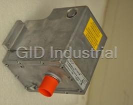
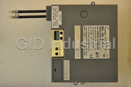
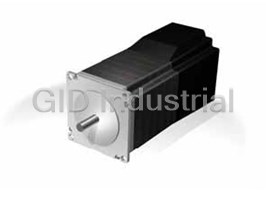
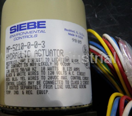


What they say about us
FANTASTIC RESOURCE
One of our top priorities is maintaining our business with precision, and we are constantly looking for affiliates that can help us achieve our goal. With the aid of GID Industrial, our obsolete product management has never been more efficient. They have been a great resource to our company, and have quickly become a go-to supplier on our list!
Bucher Emhart Glass
EXCELLENT SERVICE
With our strict fundamentals and high expectations, we were surprised when we came across GID Industrial and their competitive pricing. When we approached them with our issue, they were incredibly confident in being able to provide us with a seamless solution at the best price for us. GID Industrial quickly understood our needs and provided us with excellent service, as well as fully tested product to ensure what we received would be the right fit for our company.
Fuji
HARD TO FIND A BETTER PROVIDER
Our company provides services to aid in the manufacture of technological products, such as semiconductors and flat panel displays, and often searching for distributors of obsolete product we require can waste time and money. Finding GID Industrial proved to be a great asset to our company, with cost effective solutions and superior knowledge on all of their materials, it’d be hard to find a better provider of obsolete or hard to find products.
Applied Materials
CONSISTENTLY DELIVERS QUALITY SOLUTIONS
Over the years, the equipment used in our company becomes discontinued, but they’re still of great use to us and our customers. Once these products are no longer available through the manufacturer, finding a reliable, quick supplier is a necessity, and luckily for us, GID Industrial has provided the most trustworthy, quality solutions to our obsolete component needs.
Nidec Vamco
TERRIFIC RESOURCE
This company has been a terrific help to us (I work for Trican Well Service) in sourcing the Micron Ram Memory we needed for our Siemens computers. Great service! And great pricing! I know when the product is shipping and when it will arrive, all the way through the ordering process.
Trican Well Service
GO TO SOURCE
When I can't find an obsolete part, I first call GID and they'll come up with my parts every time. Great customer service and follow up as well. Scott emails me from time to time to touch base and see if we're having trouble finding something.....which is often with our 25 yr old equipment.
ConAgra Foods