

 Manufacturers
SEALEVEL SYSTEMS 3612

Description
KEYBOARD BESR
Part Number
3612
Price
Request Quote
Manufacturer
SEALEVEL SYSTEMS
Lead Time
Request Quote
Category
PRODUCTS - 3
Datasheet

Extracted Text
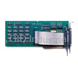
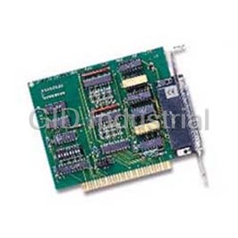
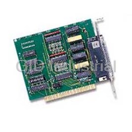
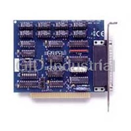
TM PC-ACB.MP USER MANUAL Part # 3612 Sealevel Systems, Inc Phone: (864) 843-4343 155 Technology Place FAX: (864) 843-3067 P.O. Box 830 www.sealevel.com Liberty, SC 29657 USA Contents INTRODUCTION.............................................................................................................................1 OVERVIEW ................................................................................................................................................... 1 WHAT’S INCLUDED ...................................................................................................................................... 1 INSTALLATION..............................................................................................................................2 TECHNICAL DESCRIPTION............................................................................................................3 FEATURES .................................................................................................................................................... 3 Internal Baud Rate Generator ................................................................................................................. 3 CONTROL AND STATUS REGISTERS DEFINITION........................................................................................... 3 INTERFACE SELECTION................................................................................................................................. 4 25 PIN CONNECTOR SIGNAL LAYOUTS (DB-25 MALE) ................................................................................ 4 RS-232 Signals ....................................................................................................................................... 4 V.35 Signals............................................................................................................................................ 5 RS-530 (RS-422) .................................................................................................................................... 5 RS-530A ................................................................................................................................................. 6 RS-485 or RS-485T ................................................................................................................................ 6 SPECIFICATIONS ...........................................................................................................................7 ENVIRONMENTAL SPECIFICATIONS .............................................................................................................. 7 POWER CONSUMPTION................................................................................................................................. 7 MEAN TIME BETWEEN FAILURES (MTBF)................................................................................................... 7 APPENDIX A - TROUBLESHOOTING..............................................................................................8 APPENDIX B - HOW TO GET ASSISTANCE ...................................................................................9 APPENDIX C - ELECTRICAL INTERFACE......................................................................................10 RS-232 ........................................................................................................................................................ 10 RS-422 ........................................................................................................................................................ 10 RS-485 ........................................................................................................................................................ 10 RS-530 / 530A............................................................................................................................................. 10 V.35............................................................................................................................................................. 11 APPENDIX D - COMPLIANCE NOTICES.........................................................................................12 FEDERAL COMMUNICATIONS COMMISSION STATEMENT.............................................................................. 12 EMC DIRECTIVE STATEMENT...................................................................................................................... 12 WARRANTY...................................................................................................................................13 © 2000i Sealevel Systems, Incorporated. All rights reserved. Introduction Introduction Overview In the last few years, the portable and notebook market has grown by leaps and bounds. Most early laptops and notebooks handled I/O expansion through proprietary expansion slots. These slots provided limited expansion for specific peripherals such as modems and FAX peripherals. Mass storage peripherals were factory installed and could not be easily changed. Interconnectivity through local area networks offered limited performance through slow parallel port network interfaces. During this time period two standards organizations, JEIDA and PCMCIA, were working on the standardization of memory IC cards. These cards were designed as strictly non-volatile silicon storage. JEIDA was the first to propose the 68-pin connector standard for memory cards. In 1989, PCMCIA adopted the JEIDA 68 pin standard and worked with JEIDA on further developments. As the notebook market grew, the need for a standard I/O bus was seen. The PCMCIA groups saw an opportunity to meet this need with an expanded version of the 68-pin interface. Further development occurred and within one year, release 2.0 of the standard was completed. Release 2.0 was a major update to Release 1.0 and included full hardware support for I/O devices. Release 2.0 coincided with JEIDA’s 4.1 release and is identical. The PC-ACB.MP adapter provides your portable PC with a single channel multi-protocol serial interface utilizing the Zilog Z85233 (ESCC™), which is suitable for the most popular communication protocols including HDLC/SDLC, X.25, Bi-Sync, Mono-Sync, and asynchronous. The PC-ACB.MP utilizes the Sipex-505 multi-protocol electrical interface chip that allows the PC-ACB.MP to be compliant with EIA/TIA-530/530A, EIA/TIA-232E, EIA/TIA-485, and ITU V.35. What’s Included The PC-ACB.MP is shipped with the following items. If any of these items are missing or damaged, contact the supplier. • PC-ACB.MP PCMCIA Serial Interface Adapter • DB-25 cable assembly • Loopback Plug • Impact Resistant Carrying Case (Jewel Case) • Sealevel Software Sealevel Systems PC-ACB.MP Page 1 Installation Installation Card and Socket Services must be loaded on the system prior to installing the PC-ACB.MP card. Card and Socket Services are supplied by the PCMCIA slot provider (i.e. the computer manufacturer or the PC adapter manufacturer). These may be in the form of a third party add-on Card and Socket service (e.g. CardSoft’s CardWizard) or with your current operating system (e.g. Windows 95/98/NT/2000). Socket Services are the lowest level of the PCMCIA Software hierarchy. Socket Services provide a standard interface to the higher-level drivers and isolate the socket controller’s specific hardware details. Socket Services provide the ‘BIOS’ interface to the socket controller hardware. Socket Services are typically hidden under Card Services and are rarely directly accessible by application software. Card Services provide the interface to application software and drivers. Card Services are responsible for allocating card resources and ensuring that card resources do not interfere with other existing system resources. Card Services are typically implemented as a driver. Almost all PCMCIA type cards require some sort of software driver. In the case of the PC-ACB.MP, the generic Card Services driver supplied with the computer system should provide adequate support for most applications. Connecting the PC-ACB.MP to the computer requires no special technical skills. In fact it is usually done in as simple as two steps: 1. Follow the directions given for your operating system found on the supplied software. 2. Simply slide the card into a PCMCIA Type II compliant slot on the personal computer. The PCMCIA slot is keyed so that the PC-ACB.MP cannot be installed backwards or upside down. The card should install with a minimal amount of pressure. Do not force the card into the slot. Forcing the card can result in damage to the PC-ACB.MP or to the PCMCIA slot. After the card has been installed into the PCMCIA slot, the I/O cable should be connected to the card. The cable is also keyed to prevent it from being installed incorrectly. 3. For Windows users that are using Sealevel’s SeaMAC software please note that there is a different install for this card than the normal SeaMAC software. When choosing to install the software from the CD scrool down to the SeaMAC drivers. You should see:* Note: If you are installing Part# 3612 or 5102, click here to install the Windows 2000 interrupt mode HDLC/SDLC driver. To install the Windows NT interrupt mode Async driver and for all other ACB products, click the "install SeaMAC" button below. Please be sure to follow these steps for a successful installation. Installation is complete. The PC-ACB.MP has a number of cabling options available. These options include: • CA-103 - This cable provides a high quality shielded cable with the V.35 mechanical specification met on one end and a DB-25S (female) on the other end. V.35 has a mechanical specification that is impossible to place on a PC bracket and requires this adapter cable. • CA-104 - This cable provides a 6’ extension for use with RS-232, and RS-530/530A. • CA-107 - RS-530 (DB-25P) to RS-449 (DB-37P) cabling adapter. RS-530 is replacing RS-449 in Telecom applications, but there is still a very large base of installed equipment that uses the RS-449 pin-out. Both standards use RS-422 to define the electrical specifications and are interchangeable via this adapter cable. Sealevel Systems PC-ACB.MP Page 2 Technical Description Technical Description The PC-ACB.MP utilizes the Zilog 85233 Enhanced Serial Communications Controller (ESCC). This chip features programmable baud rate, data format and interrupt control. Refer to the ESCC Users Manual for details on programming the 85233 ESCC chip. Features • One channel of synchronous or asynchronous communications using the Zilog Z85233 chip • Programmable electrical interface selection EIA/TIA-232/530/530A/485 and ITU V.35 • Programmable options for Transmit clock as input or output • Software programmable baud rate Internal Baud Rate Generator The baud rate of the ESCC is programmed under software control. Control and Status Registers Definition The control and status registers occupy 16 consecutive locations. The following tables provide a functional description of the bit positions. X = do not care Base Mode D7 D6 D5 D4 D3 D2 D1 D0 RD 0 IRQST 0 0 0 0 0 DSRA +4 +4 WR X X X X X X X X +5 RD 485CLK ECHOA SYNCA_RTS SYNCA_CTS AM3 AM2 AM1 AM0 WR 485CLK ECHOA SYNCA_RTS SYNCA_CTS AM3 AM2 AM1 AM0 +5 +6 RD 0 0 0 0 RLA LLA TSETSLA RXCOPTA +6 WR X X X X RLA LLA TSETSLA RXCOPTA RD SD7 SD6 SD5 SD4 SD3 SD2 SD1 SD0 +7 Field Description IRQST SCC interrupt status: 1 = No interrupt pending on ESCC 0 = Interrupt pending on ESCC. DSRA DSRA: 1 = DSRA is not active 0 = DSRA is active TSETSLA TSET clock source: 1 = Received TXC as source 0 = TRXCA as source RXCOPTA RXCOPTA: 1 = Selects SCC PCLK for RTXCA 0 = Selects received RXC for RTXCA SYNCA_RTS SYNCA _RTS: 1 = SYNCA connected to RTS 0 = SYNCA is high SYNCA_CTS SYNCA_CTS: 1 = SYNCA connected to CTS 0 = SYNCA is high 485CLK TSET switches with TXD 1 = clk switches 0 = no CLK switching ECHOA ECHO enable: 1 = echo disabled 0 = echo enabled AM0-AM3 I/O mode select. See table for valid interface options 0 = High Impedance SD0-SD7 Optional security feature. Unique value per customer or application. Default value = FF Note: Default values are listed in bold Sealevel Systems PC-ACB.MP Page 3 Technical Description Interface Selection The PC-ACB.MP supports a variety of electrical interfaces. Refer to the Control and Status Register Definitions found in the Technical Description section of this manual for this bit description. There is line termination on RXD, RXC, and TXC in the following modes: RS-530, RS-530A, RS-485T, and V.35. HEX M3 M2 M1 M0 Interface Mode 0 0 0 0 0 All signals are high impedance 1 0 0 0 1 * not supported * 2 0 0 1 0 RS-232 3 0 0 1 1 * not supported * 4 0 1 0 0 RS-485T with 120 ohm termination 5 0 1 0 1 RS-485 without termination 6,7,8,9 0 1 1 0 * not supported * A 1 0 1 0 single ended loop-back B 1 0 1 1 differential loop-back C 1 1 0 0 * not supported * D 1 1 0 1 RS-530 E 1 1 1 0 V.35 F 1 1 1 1 RS-530A 25 Pin Connector Signal Layouts (DB-25 Male) RS-232 Signals Base+5, M3-M0=2, 0010 Signal Name Pin # Mode GND Ground 7 RD Receive Data 3 Input CTS Clear To Send 5 Input DSR Data Set Ready 6 Input DCD Data Carrier Detect 8 Input TM Test Mode 25 Input TXC Transmit Clock 15 Input RXC Receive Clock 17 Input TSET Transmit Signal Element Timing 24 Output DTR Data Terminal Ready 20 Output TD Transmit Data 2 Output RTS Request To Send 4 Output Technical Note: Please terminate any control signals that are not going to be used. The most common way to do this is connect RTS to CTS and RI. Also, connect DCD to DTR and DSR. Terminating these pins, if not used, will help insure you get the best performance from your adapter. Sealevel Systems PC-ACB.MP Page 4 Technical Description V.35 Signals Base+5, M3-M0=E, 1110 Signal Name DB-25 V.35 Mode GND Ground 7 B RDB RX+ Receive Positive 16 T Input RDA RX- Receive Negative 3 R Input TXCB TXC+ Transmit Clock Positive 12 AA Input TXCA TXC- Transmit Clock Negative 15 Y Input RXCB RXC+ Receive Clock Positive 9 X Input RXCA RXC- Receive Clock Negative 17 V Input TDB TX+ Transmit Positive 14 S Output TDA TX- Transmit Negative 2 P Output TSETB TSET+ Transmit Signal Element Timing + 11 W Output TSETA TSET- Transmit Signal Element Timing - 24 U Output CTS Clear To Send 5 D Input * DSR Data Set Ready 6 E Input * DCD Data Carrier Detect 8 F Input * DTR Data Terminal Ready 20 H Output * RTS Request To Send 4 C Output * • Note: All modem control signals are single ended (un-balanced) with RS-232 signal levels. RS-530 (RS-422) Base+5, M3-M0=D, 1101 Signal Name Pin # Mode GND Ground 7 RDB RX+ Receive Positive 16 Input RDA RX- Receive Negative 3 Input CTSB CTS+ Clear To Send Positive 13 Input CTSA CTS- Clear To Send Negative 5 Input DCDB DCD+ Data Carrier Detect Positive 10 Input DCDA DCD- Data Carrier Detect Negative 8 Input TXCB TXC+ Transmit Clock Positive 12 Input TXCA TXC- Transmit Clock Negative 15 Input RXCB RXC+ Receive Clock Positive 9 Input RXCA RXC- Receive Clock Negative 17 Input TDB TX+ Transmit Positive 14 Output TDA TX- Transmit Negative 2 Output RTSB RTS+ Request To Send Positive 19 Output RTSA RTS- Request To Send Negative 4 Output DTRB DTR+ Data Terminal Ready Positive 23 Output DTRA DTR- Data Terminal Ready Negative 20 Output TSETB TSET+ Transmit Signal Element Timing Positive 11 Output TSETA TSET- Transmit Signal Element Timing Negative 24 Output DSRB DSR+ Data Set Ready Positive 22 Input DSRA DSR- Data Set Ready Negative 6 Input Sealevel Systems PC-ACB.MP Page 5 Technical Description RS-530A Base+5, M3-M0=F, 1111 Signal Name Pin # Mode GND Ground 7 RDB RX+ Receive Positive 16 Input RDA RX- Receive Negative 3 Input CTSA CTS- Clear To Send Negative 5 Input DCDA DCD- Data Carrier Detect Negative 8 Input TXCB TXC+ Transmit Clock Positive 12 Input TXCA TXC- Transmit Clock Negative 15 Input RXCB RXC+ Receive Clock Positive 9 Input RXCA RXC- Receive Clock Negative 17 Input TDB TX+ Transmit Positive 14 Output TDA TX- Transmit Negative 2 Output RTSA RTS- Request To Send Negative 4 Output DTRA DTR- Data Terminal Ready Negative 20 Output TSETB TSET+ Transmit Signal Element Timing Positive 11 Output TSETA TSET- Transmit Signal Element Timing Negative 24 Output RS-485 or RS-485T Base+5, M3-M0=4, 0100 (With termination) Base+5, M3-M0=5, 0101 (Without termination) Signal Name Pin # Mode GND Ground 7 RDB RX+ Receive Positive 16 Input RDA RX- Receive Negative 3 Input TXCB TXC+ Transmit Clock Positive 12 Input TXCA TXC- Transmit Clock Negative 15 Input RXCB RXC+ Receive Clock Positive 9 Input RXCA RXC- Receive Clock Negative 17 Input TDB TX+ Transmit Positive 14 Output TDA TX- Transmit Negative 2 Output TSETB TSET+ Transmit Signal Element Timing Positive 11 Output TSETA TSET- Transmit Signal Element Timing Negative 24 Output Sealevel Systems PC-ACB.MP Page 6 Specifications Specifications Environmental Specifications Specification Operating Storage Temperature Range 0 to 50 º C -20 to 70 º C (32 to 122 º F) (-4 to 158 ºF) Humidity Range 10 - 90% R.H. Non Condensing 10 - 90% R.H. Non Condensing Power Consumption +5 VDC Supply line Rating 170 mA Mean Time Between Failures (MTBF) Greater than 150,000 hours. (Calculated) Sealevel Systems PC-ACB.MP Page 7 Appendix A - Troubleshooting Appendix A - Troubleshooting The Developers Toolkit Software is supplied with the Sealevel Systems adapter and will be used in the troubleshooting procedures. Using this software and following these simple steps can eliminate most common problems without the need to call Technical Support. 1. Identify all I/O adapters currently installed in your system. This includes your on-board serial ports, controller cards, sound cards etc. The I/O addresses used by these adapters, as well as the IRQ (if any) should be identified. 2. Make sure the Sealevel Systems adapter is securely installed in a PCMCIA slot. 3. Use the supplied software and User Manual to verify that the Sealevel Systems adapter is configured correctly. The supplied software contains a diagnostic program “SSDMP” that will verify if an adapter is configured properly. This diagnostic program is written with the user in mind and is easy to use. 4. Windows users can use the installed programs in the SeaMAC folder to verify operation. Sealevel Systems PC-ACB.MP Page 8 Appendix B - How To Get Assistance Appendix B - How To Get Assistance Please refer to Troubleshooting Guide prior to calling Technical Support. 1. Begin by reading through the Trouble Shooting Guide in Appendix A. If assistance is still needed please see below. 2. When calling for technical assistance, please have your user manual and current adapter settings. If possible, please have the adapter installed in a computer ready to run diagnostics. 3. Sealevel Systems provides an FAQ section on its web site. Please refer to this to answer many common questions. This section can be found at http://www.sealevel.com/faq.htm . 4. Sealevel Systems maintains a Home page on the Internet. Our home page address is www.sealevel.com. The latest software updates, and newest manuals are available via our FTP site that can be accessed from our home page. 5. Technical support is available Monday to Friday from 8:00 a.m. to 5:00 p.m. eastern time. Technical support can be reached at (864) 843-4343. RETURN AUTHORIZATION MUST BE OBTAINED FROM SEALEVEL SYSTEMS BEFORE RETURNED MERCHANDISE WILL BE ACCEPTED. AUTHORIZATION CAN BE OBTAINED BY CALLING SEALEVEL SYSTEMS AND REQUESTING A RETURN MERCHANDISE AUTHORIZATION (RMA) NUMBER. Sealevel Systems PC-ACB.MP Page 9 Appendix C - Electrical Interface Appendix C - Electrical Interface RS-232 Quite possibly the most widely used communication standard is RS-232. This implementation has been defined and revised several times and is often referred to as RS-232 or EIA/TIA-232. It is defined by the EIA as the Interface between Data Terminal Equipment and Data Circuit- Terminating Equipment Employing Serial Binary Data Interchange. The mechanical implementation of RS-232 is on a 25 pin D sub connector. RS-232 is capable of operating at data rates up to 20 Kbps at distances less than 50 ft. The absolute maximum data rate may vary due to line conditions and cable lengths. RS-232 often operates at 38.4 Kbps over very short distances. The voltage levels defined by RS-232 range from -12 to +12 volts. RS-232 is a single ended or unbalanced interface, meaning that a single electrical signal is compared to a common signal (ground) to determine binary logic states. A voltage of +12 volts (usually +3 to +10 volts) represents a binary 0 (space) and -12 volts (-3 to -10 volts) denotes a binary 1 (mark). The RS-232 and the EIA/TIA-574 specification defines two type of interface circuits, Data Terminal Equipment (DTE) and Data Circuit-Terminating Equipment (DCE). The Sealevel Systems adapter is a DTE interface. RS-422 The RS-422 specification defines the electrical characteristics of balanced voltage digital interface circuits. RS-422 is a differential interface that defines voltage levels and driver/receiver electrical specifications. On a differential interface, logic levels are defined by the difference in voltage between a pair of outputs or inputs. In contrast, a single ended interface, for example RS-232, defines the logic levels as the difference in voltage between a single signal and a common ground connection. Differential interfaces are typically more immune to noise or voltage spikes that may occur on the communication lines. Differential interfaces also have greater drive capabilities that allow for longer cable lengths. RS-422 is rated up to 10 Megabits per second and can have cabling 4000 feet long. RS-422 also defines driver and receiver electrical characteristics that will allow 1 driver and up to 32 receivers on the line at once. RS-422 signal levels range from 0 to +5 volts. RS-422 does not define a physical connector. RS-485 RS-485 is backwardly compatible with RS-422; however, it is optimized for party line or multi-drop applications. The output of the RS-422/485 driver is capable of being Active (enabled) or Tri-State (disabled). This capability allows multiple ports to be connected in a multi-drop bus and selectively polled. RS-485 allows cable lengths up to 4000 feet and data rates up to 10 Megabits per second. The signal levels for RS-485 are the same as those defined by RS-422. RS-485 has electrical characteristics that allow for 32 drivers and 32 receivers to be connected to one line. This interface is ideal for multi-drop or network environments. RS-485 tri-state driver (not dual-state) will allow the electrical presence of the driver to be removed from the line. Only one driver may be active at a time and the other driver(s) must be tri-stated. RS-485 can be cabled in two ways, two wire and four wire mode. Two-wire mode does not allow for full duplex communication, and requires that data be transferred in only one direction at a time. For half-duplex operation, the two transmit pins should be connected to the two receive pins (Tx+ to Rx+ and Tx- to Rx-). Four wire mode allows full duplex data transfers. RS-485 does not define a connector pin-out or a set of modem control signals. RS-485 does not define a physical connector. RS-530 / 530A RS-530 (a.k.a. EIA-530) compatibility means that RS-422 signal levels are met, and the pin-out for the DB-25 connector is specified. The EIA (Electronic Industry Association) created the RS-530 specification to detail the pin-out, and define a full set of modem control signals that can be used for regulating flow control and line status. The major difference between RS-530 and RS-530A lies in the modem control interface signals. In RS-530 all signals are differential, in RS-530A signals DTR, DSR, DCD are single ended. The RS-530 specification defines two types of interface circuits, Data Terminal Equipment (DTE) and Data Circuit-Terminating Equipment (DCE). The Sealevel Systems adapter is a DTE interface. Sealevel Systems PC-ACB.MP Page 10 Appendix C - Electrical Interface V.35 V.35 is a standard defined by ITU (formerly CCITT) that specifies an electrical, mechanical, and physical interface that is used extensively by high-speed digital carriers such as AT&T Dataphone Digital Service (DDS). ITU V.35 is an international standard that is often refereed to as Data Transmission at 48 Kbps Using 60 - 108 KHz Group-Band Circuits. ITU V.35 electrical characteristics are a combination of unbalanced voltage and balanced current mode signals. Data and clock signals are balanced current mode circuits. These circuits typically have voltage levels from 0.5 Volts to -0.5 Volts (1 Volt differential). The modem control signals are unbalanced signals and are compatible with RS-232. The physical connector is a 34-pin connector that supports 24 data, clock and control signals. The physical connector is defined in the ISO-2593 standard. ITU V.35 specification defines two types of interface circuits, Data Terminal Equipment (DTE) and Data Circuit-Terminating Equipment (DCE). The Sealevel Systems adapter is a DTE interface. Sealevel Systems PC-ACB.MP Page 11 Appendix D – Compliance Notices Appendix D - Compliance Notices Federal Communications Commission Statement FCC - This equipment has been tested and found to comply with the limits for Class A digital device, pursuant to Part 15 of the FCC Rules. These limits are designed to provide reasonable protection against harmful interference when the equipment is operated in a commercial environment. This equipment generates, uses, and can radiate radio frequency energy and, if not installed and used in accordance with the instruction manual, may cause harmful interference to radio communications. Operation of this equipment in a residential area is likely to cause harmful interference in such case the user will be required to correct the interference at his own expense. EMC Directive Statement Products bearing the CE Label fulfill the requirements of the EMC directive (89/336/EEC) and of the low-voltage directive (73/23/EEC) issued by the European Commission. To obey these directives, the following European standards must be met: • EN55022 Class A - “Limits and methods of measurement of radio interference characteristics of information technology equipment” • EN55024-‘Information technology equipment Immunity characteristics Limits and methods of measurement. • EN60950 (IEC950) - “Safety of information technology equipment, including electrical business equipment” Warning This is a Class A Product. In a domestic environment this product may cause radio interference in which case the user may be required to take adequate measures. Always use cabling provided with this product if possible. If no cable is provided or if an alternate cable is required, use high quality shielded cabling to maintain compliance with FCC/EMC directives. U.S. Patent Nos. 4,603,320 4,686,506 4,972,470 Sealevel Systems PC-ACB.MP Page 12 Warranty Warranty Sealevel Systems, Inc. provides a limited lifetime warranty. Should this product fail to be in good working order at any time during this period, Sealevel Systems will, at it’s option, replace or repair it at no additional charge except as set forth in the following terms. This warranty does not apply to products damaged by misuse, modifications, accident or disaster. Sealevel Systems assumes no liability for any damages, lost profits, lost savings or any other incidental or consequential damage resulting from the use, misuse of, or inability to use this product. Sealevel Systems will not be liable for any claim made by any other related party. RETURN AUTHORIZATION MUST BE OBTAINED FROM SEALEVEL SYSTEMS BEFORE RETURNED MERCHANDISE WILL BE ACCEPTED. AUTHORIZATION CAN BE OBTAINED BY CALLING SEALEVEL SYSTEMS AND REQUESTING A RETURN MERCHANDISE AUTHORIZATION (RMA) NUMBER. Sealevel Systems, Incorporated 155 Technology Place P.O. Box 830 Liberty, SC 29657 USA (864) 843-4343 FAX:(864) 843-3067 www.sealevel.com email: support@sealevel.com Technical Support is available from 8 a.m. to 5 p.m. Eastern time. Monday - Friday Trademarks Sealevel Systems, Incorporated acknowledges that all trademarks referenced in this manual are the service mark, trademark, or registered trademark of the respective company. PC-ACB.MP is a trademark of Sealevel Systems, Incorporated. Sealevel Systems PC-ACB.MP Page 13
Frequently asked questions
What makes Elite.Parts unique?

What kind of warranty will the 3612 have?
Which carriers does Elite.Parts work with?
Will Elite.Parts sell to me even though I live outside the USA?
I have a preferred payment method. Will Elite.Parts accept it?


What they say about us
FANTASTIC RESOURCE
One of our top priorities is maintaining our business with precision, and we are constantly looking for affiliates that can help us achieve our goal. With the aid of GID Industrial, our obsolete product management has never been more efficient. They have been a great resource to our company, and have quickly become a go-to supplier on our list!
Bucher Emhart Glass
EXCELLENT SERVICE
With our strict fundamentals and high expectations, we were surprised when we came across GID Industrial and their competitive pricing. When we approached them with our issue, they were incredibly confident in being able to provide us with a seamless solution at the best price for us. GID Industrial quickly understood our needs and provided us with excellent service, as well as fully tested product to ensure what we received would be the right fit for our company.
Fuji
HARD TO FIND A BETTER PROVIDER
Our company provides services to aid in the manufacture of technological products, such as semiconductors and flat panel displays, and often searching for distributors of obsolete product we require can waste time and money. Finding GID Industrial proved to be a great asset to our company, with cost effective solutions and superior knowledge on all of their materials, it’d be hard to find a better provider of obsolete or hard to find products.
Applied Materials
CONSISTENTLY DELIVERS QUALITY SOLUTIONS
Over the years, the equipment used in our company becomes discontinued, but they’re still of great use to us and our customers. Once these products are no longer available through the manufacturer, finding a reliable, quick supplier is a necessity, and luckily for us, GID Industrial has provided the most trustworthy, quality solutions to our obsolete component needs.
Nidec Vamco
TERRIFIC RESOURCE
This company has been a terrific help to us (I work for Trican Well Service) in sourcing the Micron Ram Memory we needed for our Siemens computers. Great service! And great pricing! I know when the product is shipping and when it will arrive, all the way through the ordering process.
Trican Well Service
GO TO SOURCE
When I can't find an obsolete part, I first call GID and they'll come up with my parts every time. Great customer service and follow up as well. Scott emails me from time to time to touch base and see if we're having trouble finding something.....which is often with our 25 yr old equipment.
ConAgra Foods