

 Manufacturers
SEALEVEL SYSTEMS 3096
Description
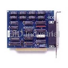
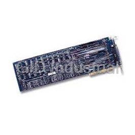
DIO-16 ISA 8 Reed Relay Output/8 Isolated Input Digital Interface
Part Number
3096
Price
Request Quote
Manufacturer
SEALEVEL SYSTEMS
Lead Time
Request Quote
Category
PRODUCTS - 3
Features
- 8 optically isolated AC or DC inputs
- 8 Reed relay outputs
- Highly reliable 10VA DIP Reed relays utilized
- Output ports have non-destructive read-back
- Selectable port address (four port boundary)
- Supports interrupts 2-7
Datasheet

Extracted Text
DIO-16 Users Manual Part # DIO-16 Sealevel Systems, Inc. Telephone: 864.843.4343 155 Technology Place Fax: 864.843.3067 Liberty, SC 29657 USA www.sealevel.com Contents INTRODUCTION........................................................................................................................ 1 OVERVIEW .............................................................................................................................................. 1 WHAT’S INCLUDED ................................................................................................................................. 1 FACTORY DEFAULT SETTINGS ................................................................................................................ 1 CARD SETUP ............................................................................................................................ 2 ADDRESS SELECTION .............................................................................................................................. 2 IRQ HEADER E2 ..................................................................................................................................... 3 INSTALLATION......................................................................................................................... 4 Windows 98/ME/NT/2000/XP Installation......................................................................................... 4 Linux Installation ................................................................................................................................ 5 TECHNICAL DESCRIPTION....................................................................................................... 6 FEATURES ............................................................................................................................................... 6 INPUT PORTS........................................................................................................................................... 6 Sensor Input Port Pin Assignments (P1) ............................................................................................. 7 OUTPUT PORTS (REED RELAY) ............................................................................................................... 7 RELAY SPECIFICATIONS .......................................................................................................................... 7 Output Ports (Reed Relay) Pin Assignments (P1)............................................................................... 8 Power and Ground Pin Assignments................................................................................................... 8 PROGRAMMING ....................................................................................................................... 9 APPLICATION PROGRAMMERS INTERFACE (API) .................................................................................... 9 DIRECT HARDWARE CONTROL................................................................................................................ 9 Reading the Inputs............................................................................................................................... 9 Reading the Outputs (relays)............................................................................................................... 9 Writing the Outputs (relays)................................................................................................................ 9 SPECIFICATIONS .................................................................................................................... 10 ENVIRONMENTAL SPECIFICATIONS ....................................................................................................... 10 MANUFACTURING ................................................................................................................................. 10 POWER CONSUMPTION.......................................................................................................................... 10 PHYSICAL DIMENSIONS......................................................................................................................... 10 APPENDIX A - TROUBLESHOOTING....................................................................................... 11 APPENDIX B - HOW TO GET ASSISTANCE ............................................................................ 12 APPENDIX C - SILK-SCREEN ................................................................................................. 13 APPENDIX D - COMPLIANCE NOTICES.................................................................................. 14 FEDERAL COMMUNICATIONS COMMISSION STATEMENT....................................................................... 14 EMC DIRECTIVE STATEMENT............................................................................................................... 14 WARRANTY............................................................................................................................ 15 © Revision February 27, 2004 Sealevel Systems, Incorporated. All rights reserved. Introduction Introduction Overview The DIO-16 provides 8 reed relays that can latch power, data or other electronic signals for control applications and 8 optically isolated inputs to allow monitoring of off board switch closures, relays or for any other general purpose monitoring needs. The DIO-16 is simple to operate. By writing instruction bytes to the I/O port addresses, the reed relays are energized or de-energized. Inputs are just as simply read from their data ports. What’s Included The DIO-16 is shipped with the following items. If any of these items are missing or damaged, contact the supplier. • DIO-16 Interface Adapter • Sealevel SeaIO Software CD Factory Default Settings The DIO-16 factory default settings are as follows: Base Address IRQ 300 5 To install the DIO-16 using factory default settings, refer to Installation on page 4. For your reference, record installed DIO-16 settings below: Base Address IRQ Sealevel Systems DIO-16 Page 1 Card Setup Card Setup The DIO-16 contains several jumper straps for each port which must be set for proper operation. Address Selection The DIO-16 occupies 4 consecutive I/O locations. The DIP-switch (SW1) is used to set the base address for these locations. Be careful when selecting the base address as some selections conflict with existing PC ports. The following table shows several examples that usually do not cause a conflict. Address Binary Switch Settings 1 2 3 4 5 6 7 8 100-104 01 0000 00xx Off On On On On On On On 104-108 01 0000 01xx Off On On On On On On Off 200-204 10 0000 00xx On Off On On On On On On 280-283 10 1000 00xx Off On Off On On On On On 284-287 10 1000 01xx Off On Off On Off On On Off 2EC-2EF 10 1110 11xx Off On Off Off Off On Off Off 300-303 11 0000 00xx Off Off On On On On On On 320-323 11 0010 00xx Off Off On On Off On On On 388-38B 11 1000 10xx Off Off Off On On On Off On 3A0-3A3 11 1010 00xx Off Off Off On Off On On On 3A4-3A7 11 1010 01xx Off Off Off On Off On On Off Figure 1 - Address Selection Table The following illustration shows the correlation between the DIP-switch setting and the address bits used to determine the base address. In the example below, address 300 is selected as the base address. Address 300 in binary is XX 11 0000 00XX where X = a non-selectable address bit and address bit A9 is always a 1. A9 A2 ON OFF 1 2 3 4 5 6 7 8 Figure 2 - DIP-Switch Illustration Note: Setting the switch ‘On’ or ‘Closed’ corresponds to a ‘0’ in the address, while leaving it ‘Off’ or ‘Open’ corresponds to a ‘1’. Sealevel Systems DIO-16 Page 2 Card Setup IRQ Header E2 Interrupts can be generated by Port A, bit 0 going low if enabled at jumper location E2. Interrupt request signals 2/9 through 7 (IRQ 2/9 - 7) can be selected by placing the jumper in the appropriate position. 7 6 5 4 3 2/9 Figure 3 - IRQ Header E2 Sealevel Systems DIO-16 Page 3 IRQ E1 Installation Installation Windows 98/ME/NT/2000/XP Installation Do not install the Adapter in the machine until the software has been fully installed. 1. Start Windows. 2. Insert the Sealevel Systems CD in to your CD drive. 3. If ‘Auto-Start’ is enabled for this drive the software will automatically launch. Otherwise, point your browser to the ‘Index.htm’ on the root of the CD 4. Select ‘Install Software’. 5. Select the part number for your adapter from the listing. 6. Select ‘Windows 98/ME/NT/2000/XP’ the setup file will automatically detect the operating environment and install the proper components. Next (depending on the OS version) select the ‘Run Here’ or ‘Open’ option. Follow the information presented on the screens that follow. During setup the user may specify installation directories and other preferred configurations. This program also adds entries to the system registry that are necessary for specifying the operating parameters for each driver. An uninstall option is also available to remove SeaIO files and registry/INI file entries from the system. 7. Go to the "Add New Hardware Wizard" in the Control Panel. 8. When the Wizard asks if you want Windows to search for the new hardware, choose "No, I want to select the hardware from a list." 9. Scroll through the list of categorized hardware and select "SeaI/O Devices." 10. Click "Next." 11. Select the card model and press "Next." Once a Categorized list of hardware appears, select "Other Devices," and click "Next." 12. The Wizard will guide you through a few more informational prompts; continue to click "Next" until it is completed. 13. Your card's resource assignments may be adjusted through the Device Manager (if, for instance, you need to change the I/O port address Windows assigned when you installed the card). 14. Windows software installation is complete Sealevel Systems DIO-16 Page 4 Installation Linux Installation Note: You need to have "root" privileges to install the software and drivers. 1. Login as "root". 2. Mount the CDROM by typing: mount -t iso9660 /dev/hdc /cdrom Note Your cdrom may not be /dev/hdc it could be /dev/hda, /dev/hdb, /dev/hdd, or if you have a SCSI drive /dev/sda, /dev/sdb, /dev/sdc, etc. You may mount the CDROM to any location, the /cdrom is just a common example. 3. Next change to the directory where you mounted the CDROM: Ex. cd /cdrom/software/seaio/Other/linux Note: The syntax is case sensitive. 4. Copy seaio.tar.gz to your home directory by typing: cp seaio.tar.gz ~ 5. Change to your home directory by typing: cd 6. Unmount the drive and then Unzip and Untar the drivers and software by typing: umount /cdrom tar -xvzf seaio.tar.gz 7. Change to the seaio directory by typing: cd seaio 8. Now compile and prepare the drivers for use: make install 9. Using your favorite text editor, edit the /etc/seaio.conf 10. Within the quote marks, insert cardtype=0xYourSeaIOcardType io=0xCardBaseAddress Note: YourSeaIOcardType = Model Number of your SeaIO Card. CardBaseAddress = What base address you have your SeaIO card addressed at. 11. Save the file and exit your editor. 12. Load the driver by typing: seaio-load 13. The driver has enabled the card and is ready to use. To set up Linux to automatically load the driver; refer to a Linux manual concerning your specific distribution for help. Sealevel Systems DIO-16 Page 5 Technical Description Technical Description The DIO-16 provides two parallel input/output (I/O) ports. The ports are organized as ports A, B, C, and D. Port A is an input port interfaced to optically-isolated inputs, while port C is the reed relay output port. Assuming an I/O address of 300 Hex the following table shows the Port Addresses. Note: Ports B and Port D are decoded but not used. Base Address Hex Decimal Mode Port A Address 300 768 Input Port (Opto-Isolator Input) Port B Address 301 769 Not Used Port C Address 302 770 Output Port (Reed Relays) Port D Address 303 771 Not Used Features • Selectable I/O port addressing from 100H - 3FFH • 1 set SPST relays with each set having 8 relays • 1 eight bit input port • DB-37 female connector • Highly reliable 10 VA DIP reed relays utilized • 8 bit slot connector • Multiple adapters can reside in same computer • All address, data and control signals are TTL compatible Input Ports Port A is 8 bit input port connected to optically isolated input sensors. Each sensor can be used to interface a voltage input and then sense whether the voltage is on or off. Each sensor is isolated (with respect to a common ground) from every other sensor, and also isolated with respect to the host PC ground. This means that signals such as low- level AC line voltage, motor servo voltage, and control relay signals can be ‘sensed’, or read by the PC, without the risk of damage due to ground loops or ground faults. Each sensor input pair has a current limiting resistor which is used to limit the input current to the opto-isolator. The opto-isolator has two ‘back-to-back’ diodes internally. This allows AC or DC signals to be sensed, regardless of polarity. When the applied voltage is high enough to cause the LED in the opto-isolator to turn-on, the output of the opto-isolator goes low (0 volts) and the signal is read as a low logic level (binary 0) by the PC. When the input signal is too low to turn on the opto-isolator, the output goes high and the port bit is read by the PC as a high logic level (binary 1). The input impedance of each isolated input is approximately 560 ohms (factory default). The opto-isolator requires approximately 3 mA to turn on. The maximum input current is 60 mA. Two things to consider when selecting the input resistor. The first is turn on voltage for the circuit to sense, and second is the maximum input voltage. Maximum input voltage must not provide too much power to the input resistor, and must also not overdrive the opto-isolator input current specification. The following formulas apply: Turn on current: 3 mA Isolator diode drop: 1.1 V Resistor power Max: .25 W Turn on Voltage = diode drop + (turn on current) x ( resistance) Or : 1.1 + (.003) x R Sealevel Systems DIO-16 Page 6 Technical Description Maximum voltage = square root of (.25 (resistor value)) The following table shows four common input resistors and the ranges associated with each . Input Resistor Min Turn-On Max Input Max Current (Ohms) (Volts) (Volts) (mA) 220 1.76 7 32 560 2.8 12 22 1K 4.1. 16 16 2.2K 7.7 24 11 The maximum input voltage can be increased by increasing the input resistor accordingly. Because socketed DIP resistor networks are utilized, they can easily be replaced with a different value. This can be done at the factory, if necessary. The input circuits are not intended for monitoring 120 volt AC circuits. In addition to being too high a voltage for the circuits, it is dangerous to have that high a voltage on the card. Sensor Input Port Pin Assignments (P1) Port A Bit P1 0 2,20 1 3,21 2 4,22 3 5,23 4 6,24 5 7,25 6 8,26 7 9,27 Output Ports (Reed Relay) Reed relays provide very high quality, long life, low current (10 Watt maximum), dry contact switch closures. Reed relays are not suited for high current applications, and can be destroyed by inductive load switching, where a spark occurs across the contacts internally. The relays are normally open, and close when energized. Each relay can be individually energized by writing a ‘1’ to the proper port bit. Relay Specifications • Contact Power Ratings: 10 Watts Maximum • Contact Voltage Maximum: 100 Volts DC or AC Maximum • Contact Current Maximum: .5 Amps DC or AC RMS • Contact Resistance, Initial: .15 Ohms • Rated Life: Low Load: 200 Million Closures Maximum Load: 100 Million Closures • Contact Speed: Operate: .5 m Sec Release: .5 m Sec Bounce: .5 m Sec • Maximum Operating Speed: 600 Hertz Sealevel Systems DIO-16 Page 7 Technical Description Output Ports (Reed Relay) Pin Assignments (P1) Port C Bit Relay P2 Pin 0 K1 10,28 1 K2 11,29 2 K3 12,30 3 K4 13,31 4 K5 14,32 5 K6 15,33 6 K7 16,34 7 K8 17,35 Power and Ground Pin Assignments Ground 18,36,37 + 5 Volts 19 + 12 Volts 1 Sealevel Systems DIO-16 Page 8 Technical Description Programming Application Programmers Interface (API) Most modern operating systems do not allow direct hardware access. The SeaIO driver and API have been included to provide control over the hardware in Windows and Linux environments. Complete documentation of the API can be found in its accompanying help file. Direct Hardware Control In systems where the users program has direct access to the hardware (DOS) the table below gives the mapping and functions which the DIO-16 provides, a base address of 300 was used. If a different base address is used then the port addresses are calculated as shown in the table. Reading the Inputs The inputs are active Low. If no voltage is applied across one of the differential inputs it returns a one on that bit. If an AC or DC voltage (of sufficient magnitude, covered above) is applied it returns a zero on that bit. Reading the Outputs (relays) The relay ports return the ones complement of the value that is currently being used to drive the relays. When using the API the value is returned not the complement of the value. Writing the Outputs (relays) The output ports are the only ports that can be written. The relays on a standard DIO-16 are normally open. To close a relay a one must be written to the appropriate bit. R = Read W = Write R/W = Read or Write Function Port Address Hex Address Port Type Available Decimal R A 300 (Base + 0) 768 Input Port (Opto Input) B 301(Base + 1) 769 Not Used R/W C 302 (Base + 2) 770 Output Port (Reed Relays) D 303 (Base + 3) 771 Not Used Sealevel Systems DIO-16 Page 9 Specifications Specifications Environmental Specifications Specification Operating Storage Temperature 0º to 70º C -50º to 105º C Range (32º to 158º F) (-58º to 221º F) 10 to 90% R.H. 10 to 90% R.H. Humidity Range Non-Condensing Non-Condensing Manufacturing All Sealevel Systems Printed Circuit boards are built to UL 94V0 rating and are 100% electrically tested. These printed circuit boards are solder mask over bare copper or solder mask over tin nickel. Power Consumption Supply line +5 VDC 270 mA Rating Physical Dimensions Board length 4.9 inches (12.446 cm) Board Height including Goldfingers 4.2 inches (10.66 cm) Board Height excluding Goldfingers 3.9 inches (9.906 cm) Note: Please see Appendix C for board layout and dimensions. Sealevel Systems DIO-16 Page 10 Appendix A - Troubleshooting Appendix A - Troubleshooting 1. Identify all I/O adapters currently installed in your system. This includes your on-board serial ports, controller cards, sound cards etc. 2. Configure your Sealevel Systems adapter so that there is no conflict with currently installed adapters. No two adapters can occupy the same I/O address. 3. Make sure the Sealevel Systems adapter is securely installed in a motherboard slot. 4. The following are known I/O conflicts: • The 278 and 378 settings may conflict with your printer I/O adapter. • 3B0 cannot be used if a Monochrome adapter is installed. • 3F8-3FF is typically reserved for COM1: • 2F8-2FF is typically reserved for COM2: • 3E8-3EF is typically reserved for COM3: • 2E8-2EF is typically reserved for COM4: Sealevel Systems DIO-16 Page 11 Appendix B - How To Get Assistance Appendix B - How To Get Assistance Please refer to Troubleshooting Guide prior to calling Technical Support. 1. Begin by reading through the Trouble Shooting Guide in Appendix A. If assistance is still needed please see below. 2. When calling for technical assistance, please have your user manual and current adapter settings. If possible, please have the adapter installed in a computer ready to run diagnostics. 3. Sealevel Systems provides an FAQ section on its web site. Please refer to this to answer many common questions. This section can be found at http://www.sealevel.com/faq.asp. 4. Sealevel Systems maintains a web page on the Internet. Our home page address is http://www.sealevel.com. The latest software updates, and newest manuals are available via our web site. 5. Technical support is available Monday to Friday from 8:00 a.m. to 5:00 p.m. eastern time. Technical support can be reached at (864) 843-4343. Return Authorization Must Be Obtained From Sealevel Systems Before Returned Merchandise Will Be Accepted. Authorization Can Be Obtained By Calling Sealevel Systems And Requesting A Return Merchandise Authorization (RMA) Number. Sealevel Systems DIO-16 Page 12 Appendix C - Silk-Screen Appendix C - Silk-Screen 4.2" 4.9" 3.9" Sealevel Systems DIO-16 Page 13 Appendix D - Compliance Notices Appendix D - Compliance Notices Federal Communications Commission Statement FCC - This equipment has been tested and found to comply with the limits for Class A digital device, pursuant to Part 15 of the FCC Rules. These limits are designed to provide reasonable protection against harmful interference when the equipment is operated in a commercial environment. This equipment generates, uses, and can radiate radio frequency energy and, if not installed and used in accordance with the instruction manual, may cause harmful interference to radio communications. Operation of this equipment in a residential area is likely to cause harmful interference in such case the user will be required to correct the interference at the users expense. EMC Directive Statement Products bearing the CE Label fulfill the requirements of the EMC directive (89/336/EEC) and of the low-voltage directive (73/23/EEC) issued by the European Commission. To obey these directives, the following European standards must be met: EN55022 Class A - “Limits and methods of measurement of radio interference characteristics of information technology equipment” EN55024 – “Information technology equipment Immunity characteristics Limits and methods of measurement”. EN60950 (IEC950) - “Safety of information technology equipment, including electrical business equipment” Warning This is a Class A Product. In a domestic environment, this product may cause radio interference in which case the user may be required to take adequate measures to prevent or correct the interference. Always use cabling provided with this product if possible. If no cable is provided or if an alternate cable is required, use high quality shielded cabling to maintain compliance with FCC/EMC directives. Sealevel Systems DIO-16 Page 14 Warranty Warranty Sealevel's commitment to providing the best I/O solutions is reflected in the Lifetime Warranty that is standard on all Sealevel manufactured products. We are able to offer this warranty due to our control of manufacturing quality and the historically high reliability of our products in the field. Sealevel products are designed and manufactured at its Liberty, South Carolina facility, allowing direct control over product development, production, burn-in and testing. Sealevel Systems, Inc. (hereafter "Sealevel") warrants that the Product shall conform to and perform in accordance with published technical specifications and shall be free of defects in materials and workmanship for life. In the event of failure, Sealevel will repair or replace the product at Sealevel's sole discretion. Failures resulting from misapplication or misuse of the Product, failure to adhere to any specifications or instructions, or failure resulting from neglect or abuse are not covered under this warranty. Warranty service is obtained by delivering the Product to Sealevel and providing proof of purchase. Return authorization must be obtained from Sealevel Systems before returned merchandise will be accepted. Authorization is obtained by calling Sealevel Systems and requesting a Return Merchandise Authorization (RMA) number. The Customer agrees to insure the Product or assume the risk of loss or damage in transit, to prepay shipping charges to Sealevel, and to use the original shipping container or equivalent. Warranty is valid only for original purchaser and is not transferable. Sealevel Systems assumes no liability for any damages, lost profits, lost savings or any other incidental or consequential damage resulting from the use, misuse of, or inability to use this product. Sealevel Systems will not be liable for any claim made by any other related party. This warranty applies to Sealevel manufactured Product. Product purchased through Sealevel but manufactured by a third party will retain the original manufacturer's warranty. Sealevel Systems, Incorporated 155 Technology Place P.O. Box 830 Liberty, SC 29657 USA (864) 843-4343 FAX: (864) 843-3067 www.sealevel.com email: support@sealevel.com Technical Support is available from 8 a.m. to 5 p.m. Eastern time. Monday - Friday Trademarks Sealevel Systems, Incorporated acknowledges that all trademarks referenced in this manual are the service mark, trademark, or registered trademark of the respective company. DIO-16 is a trademark of Sealevel Systems, Incorporated. Sealevel Systems DIO-16 Page 15
Frequently asked questions
What makes Elite.Parts unique?

What kind of warranty will the 3096 have?
Which carriers does Elite.Parts work with?
Will Elite.Parts sell to me even though I live outside the USA?
I have a preferred payment method. Will Elite.Parts accept it?


What they say about us
FANTASTIC RESOURCE
One of our top priorities is maintaining our business with precision, and we are constantly looking for affiliates that can help us achieve our goal. With the aid of GID Industrial, our obsolete product management has never been more efficient. They have been a great resource to our company, and have quickly become a go-to supplier on our list!
Bucher Emhart Glass
EXCELLENT SERVICE
With our strict fundamentals and high expectations, we were surprised when we came across GID Industrial and their competitive pricing. When we approached them with our issue, they were incredibly confident in being able to provide us with a seamless solution at the best price for us. GID Industrial quickly understood our needs and provided us with excellent service, as well as fully tested product to ensure what we received would be the right fit for our company.
Fuji
HARD TO FIND A BETTER PROVIDER
Our company provides services to aid in the manufacture of technological products, such as semiconductors and flat panel displays, and often searching for distributors of obsolete product we require can waste time and money. Finding GID Industrial proved to be a great asset to our company, with cost effective solutions and superior knowledge on all of their materials, it’d be hard to find a better provider of obsolete or hard to find products.
Applied Materials
CONSISTENTLY DELIVERS QUALITY SOLUTIONS
Over the years, the equipment used in our company becomes discontinued, but they’re still of great use to us and our customers. Once these products are no longer available through the manufacturer, finding a reliable, quick supplier is a necessity, and luckily for us, GID Industrial has provided the most trustworthy, quality solutions to our obsolete component needs.
Nidec Vamco
TERRIFIC RESOURCE
This company has been a terrific help to us (I work for Trican Well Service) in sourcing the Micron Ram Memory we needed for our Siemens computers. Great service! And great pricing! I know when the product is shipping and when it will arrive, all the way through the ordering process.
Trican Well Service
GO TO SOURCE
When I can't find an obsolete part, I first call GID and they'll come up with my parts every time. Great customer service and follow up as well. Scott emails me from time to time to touch base and see if we're having trouble finding something.....which is often with our 25 yr old equipment.
ConAgra Foods