

 Manufacturers
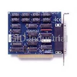
SEALEVEL SYSTEMS 3098
Description
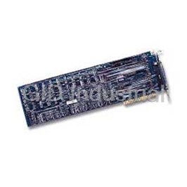
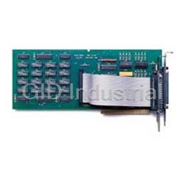
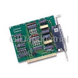
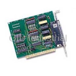
REL-32 ISA 32 Switched Relay Output Digital Interface
Part Number
3098
Price
Request Quote
Manufacturer
SEALEVEL SYSTEMS
Lead Time
Request Quote
Category
PRODUCTS - 3
Features
- 32 Reed relay outputs
- 4 sets SPST relays with each set having 8 relays
- Highly reliable 10 VA DIP Reed relays
- Multiple switching combinations enable
- Selectable I/O port addressing from 200H - 3F8H
- Switch power, data and other electronic signals
Datasheet

Extracted Text
™ REL-32 USER’S MANUAL Part Number 3098 Sealevel Systems, Inc Phone: (864) 843-4343 155 Technology Place Fax: (864) 843-3067 P.O. Box 830 www.sealevel.com Liberty, SC 29657 Contents INTRODUCTION ........................................................................ 1 OVERVIEW ........................................................................................... 1 WHAT’S INCLUDED ............................................................................. 1 FACTORY DEFAULT SETTINGS ............................................................. 1 CARD SETUP............................................................................. 2 ADDRESS SELECTION ........................................................................... 2 OPTIONS HEADER................................................................................ 3 HEADER JP1 ....................................................................................... 4 OPTIONAL CABLE CONNECTOR P4...................................................... 4 INSTALLATION.......................................................................... 5 SOFTWARE INSTALLATION.................................................................. 5 For Windows Users....................................................................... 5 TECHNICAL DESCRIPTION ....................................................... 6 FEATURES ........................................................................................... 6 CONNECTOR PIN ASSIGNMENTS........................................................... 7 PROGRAMMING....................................................................... 8 APPLICATION PROGRAMMERS INTERFACE (API)................................. 8 Relative Addressing Vs. Absolute Addressing............................ 8 DIRECT HARDWARE CONTROL..........................................................10 Reading the Outputs (relays) (direct) : ......................................10 Writing the Outputs (relays) (direct) : ......................................10 SPECIFICATIONS..................................................................... 11 ENVIRONMENTAL SPECIFICATIONS....................................................11 POWER CONSUMPTION......................................................................11 MEAN TIME BETWEEN FAILURES (MTBF)........................................11 PHYSICAL DIMENSIONS.....................................................................11 APPENDIX A - TROUBLESHOOTING....................................... 12 APPENDIX B - HOW TO GET ASSISTANCE............................. 13 APPENDIX C - ELECTRICAL INTERFACE................................ 14 RELAY SPECIFICATIONS.....................................................................14 APPENDIX D - SILK-SCREEN.................................................. 15 APPENDIX E - SCHEMATIC..................................................... 16 WARRANTY............................................................................ 22 Trademarks...................................................................................22 Figures Figure 1 - Address Selection Table ..................................................................2 Figure 2 - DIP-Switch Illustration.....................................................................2 Figure 3 - Options Header P1-P3 .....................................................................3 Figure 4 - Header JP1.......................................................................................4 Figure 5 - DB-37 Connector Pin Assignments.................................................7 ©Copyright Sealevel Systems, Incorporated 2002a. All rights reserved. Introduction Introduction Overview The REL-32 provides 32 reed relays that can latch power, data or other electronic signals for control applications. The REL-32 is PC compatible and fits any ISA or EISA slot. Addressing, data and control signals are TTL compatible. The REL-32 is simple to operate. By writing instruction bytes to the I/O port addresses, the reed relays are energized or de-energized. What’s Included The REL-32 is shipped with the following items. If any of these items are missing or damaged, contact the supplier. · REL-32 Relay Interface Adapter · 3.5” DIO Diskette · User manual Factory Default Settings The REL-32 factory default settings are as follows: Base Address 300 To install the REL-32 using factory default settings, refer to Installation on page 5. For your reference, record installed REL-32 settings below: Base Address Sealevel Systems REL-32 Page 1 Card Setup Card Setup The REL-32 contains several jumper straps for each port which must be set for proper operation. Address Selection The REL-32 occupies 4 consecutive I/O locations. The DIP-switch (SW1) is used to set the base address for these locations. Be careful when selecting the base address as some selections conflict with existing PC ports. The following table shows several examples that usually do not cause a conflict. Address Binary SW1 Switch Position Setting Hex A8 A3 6 5 4 3 2 1 280-283 0 1 0 0 0 0 On Off On On On On 288-28A 0 1 0 0 0 1 On Off On On On Off 2A0-2A3 0 1 0 1 0 0 On Off On Off On On 328-32B 1 0 0 1 0 1 Off On On Off On Off 330-333 1 0 0 1 1 0 Off On On Off Off On Figure 1 - Address Selection Table The following illustration shows the correlation between the DIP-switch setting and the address bits used to determine the base address. In the example below, address 300 is selected as the base address. Address 300 in binary is XXX 100000 XXX where X = a non-selectable address bit and address bit A9 is always a 1. ON 1 2 3 4 5 6 Figure 2 - DIP-Switch Illustration Note: Setting the switch "On" or "Closed" corresponds to a "0" in the address, while leaving it "Off" or "Open" corresponds to a "1". Relay addressing Base + 0 D0 - D7 = Switch 1 - Switch 8 Base + 1 D0 - D7 = Switch 9 - Switch 16 Base + 2 D0 - D7 = Switch 17 - Switch 24 Base + 3 D0 - D7 = Switch 25 - Switch 32 Sealevel Systems REL-32 Page 2 A3 A4 A5 A6 A7 A8 Card Setup Options Header P1 Function P2 Function P3 Function 1 Switch 1B 1 Common 1 1 Switch 1A 2 Switch 2B 2 Common 1 2 Switch 2A 3 Switch 3B 3 Common 1 3 Switch 3A 4 Switch 4B 4 Common 1 4 Switch 4A 5 Switch 5B 5 Common 1 5 Switch 5A 6 Switch 6B 6 Common 1 6 Switch 6A 7 Switch 7B 7 Common 1 7 Switch 7A 8 Switch 8B 8 Common 1 8 Switch 8A 9 Switch 9B 9 Common 2 9 Switch 9A 10 Switch 10B 10 Common 2 10 Switch 10A 11 Switch 11B 11 Common 2 11 Switch 11A 12 Switch 12B 12 Common 2 12 Switch 12A 13 Switch 13B 13 Common 2 13 Switch 13A 14 Switch 14B 14 Common 2 14 Switch 14A 15 Switch 15B 15 Common 2 15 Switch 15A 16 Switch 16B 16 Common 2 16 Switch 16A 17 Switch 17B 17 Common 3 17 Switch 17A 18 Switch 18B 18 Common 3 18 Switch 18A 19 Switch 19B 19 Common 3 19 Switch 19A 20 Switch 20B 20 Common 3 20 Switch 20A 21 Switch 21B 21 Common 3 21 Switch 21A 22 Switch 22B 22 Common 3 22 Switch 22A 23 Switch 23B 23 Common 3 23 Switch 23A 24 Switch 24B 24 Common 3 24 Switch 24A 25 Switch 25B 25 Common 4 25 Switch 25A 26 Switch 26B 26 Common 4 26 Switch 26A 27 Switch 27B 27 Common 4 27 Switch 27A 28 Switch 28B 28 Common 4 28 Switch 28A 29 Switch 29B 29 Common 4 29 Switch 29A 30 Switch 30B 30 Common 4 30 Switch 30A 31 Switch 31B 31 Common 4 31 Switch 31A 32 Switch 32B 32 Common 4 32 Switch 32A 33 GND 33 Common 1 33 5V/12V 34 GND 34 Common 2 34 5V/12V 35 GND 35 Common 3 35 5V/12V 36 GND 36 Common 4 36 5V/12V Figure 3 - Options Header P1, P2 and P3 Note: The REL-32 is shipped with jumpers connecting the first 36 pins of headers P1 and P2. This connects the B-side of the relay banks to ground, which appear at the on-board DB-37. Sealevel Systems REL-32 Page 3 Card Setup Header JP1 Header JP1 provides a means of connecting +5 VDC and +12 VDC from the PC bus, to the Options Header. The center pin of this header is connected to P3 pins 33-36. JP1 Figure 4 - Header JP1 (Factory Default +5V) Optional Cable Connector P4 Discrete access to both sides of all relays is provided by attaching the optional cable (CA-108) to pin header P4 with the colored edge of the ribbon cable attached to pin one. Removing all the jumpers connecting row P1 to P2 places the A-side of each relay at the on-board DB-37 and the B-side at the optional cable’s DB-37. Sealevel Systems REL-32 Page 4 Installation Installation The REL-32 can be installed in any of the PC expansion slots. The REL-32 contains a DIP-switch (SW1) which must be set prior to installation. 1. Turn off PC power. Disconnect the power cord. 2. Remove the PC case cover. 3. Locate an available slot and remove the blank metal slot cover. 4. Gently insert the REL-32 into the slot. Make sure the adapter is seated properly. 5. Cabling: The REL-32 has an optional cable (CA-108) that may be installed prior to use. This cable is keyed and can only be installed one way. Please do not try to force this cable as damage to the adapter may occur. 6. Replace the cover. 7. Connect the power cord. Installation is complete. Software Installation For Windows Users Choose Install Software at the beginning of the CD and select the Digital I/O software drivers and install SeaIO. Sealevel Systems REL-32 Page 5 Technical Description Technical Description The REL-32 Relay Output Adapter provides four parallel input/output (I/O) ports. The ports are organized as ports A, B, C and D and are reed relay output ports. Features · Selectable I/O port addressing from 200H - 3F8H · 4 sets SPST relays with each set having 8 relays · DB-37 female connector for relay outputs · Highly reliable 10 VA DIP reed relays utilized · 8 bit slot connector · Multiple adapters can reside in same computer · All address, data and control signals are TTL compatible Sealevel Systems REL-32 Page 6 Technical Description Connector Pin Assignments DB-37A Function Common DB-37B Function Common 1 Ground N/A 1 Ground N/A 2 Switch 2A 1 2 Switch 2B 1 3 Switch 4A 1 3 Switch 4B 1 4 Switch 6A 1 4 Switch 6B 1 5 Switch 8A 1 5 Switch 8B 1 6 Switch 10A 2 6 Switch 10B 2 7 Switch 12A 2 7 Switch 12B 2 8 Switch 14A 2 8 Switch 14B 2 9 Switch 16A 2 9 Switch 16B 2 10 Switch 18A 3 10 Switch 18B 3 11 Switch 20A 3 11 Switch 20B 3 12 Switch 22A 3 12 Switch 22B 3 13 Switch 24A 3 13 Switch 24B 3 14 Switch 26A 4 14 Switch 26B 4 15 Switch 28A 4 15 Switch 28B 4 16 Switch 30A 4 16 Switch 30B 4 17 Switch 32A 4 17 Switch 32B 4 18 Common 2 N/A 18 19 Common 4 N/A 19 20 Switch 1A 1 20 Switch 1B 1 21 Switch 3A 1 21 Switch 3B 1 22 Switch 5A 1 22 Switch 5B 1 23 Switch 7A 1 23 Switch 7B 1 24 Switch 9A 2 24 Switch 9B 2 25 Switch 11A 2 25 Switch 11B 2 26 Switch 13A 2 26 Switch 13B 2 27 Switch 15A 2 27 Switch 15B 2 28 Switch 17A 3 28 Switch 17B 3 29 Switch 19A 3 29 Switch 19B 3 30 Switch 21A 3 30 Switch 21B 3 31 Switch 23A 3 31 Switch 23B 3 32 Switch 25A 4 32 Switch 25B 4 33 Switch 27A 4 33 Switch 27B 4 34 Switch 29A 4 34 Switch 29B 4 35 Switch 31A 4 35 Switch 31B 4 36 Common 1 N/A 36 Common 1 N/A 37 Common 3 N/A 37 Figure 5 - DB-37 Connector Pin Assignments In the REL-32 adapter’s default setting, all relay connections appear at the on-board DB-37. Note: Off-board and on-board pin connections are identical except that commons 2, 3, and 4 do not appear on the B-side connector. Sealevel Systems REL-32 Page 7 Technical Description Programming Application Programmers Interface (API) Most modern operating systems do not allow direct hardware access. The SeaIO driver and API have been included to provide control over the hardware in Windows and Linux environments. The purpose of this section of the manual is to help the customer with the mapping of the API to the actual relays for the 3098 specifically. Complete documentation of the API can be found in its accompanying help file. Relative Addressing Vs. Absolute Addressing The SeaIO API makes a distinction between “absolute” and “relative” addressing modes. In absolute addressing mode, the Port argument to the API function acts as a simple byte offset from the base I/O address of the device. For instance, Port #0 refers to the I/O address base + 0; Port #1 refers to the I/O address base + 1. Relative addressing mode, on the other hand, refers to input and output ports in a logical fashion. With a Port argument of 0 and an API function th meant to output data, the first (0 ) output port on the device will be utilized. Likewise, with a Port argument of 0 and an API function th designed to input data, the first (0 ) input port of the device will be utilized. In all addressing modes, port numbers are zero-indexed; that is, the first port is port #0, the second port is #1, the third #2, and so on. Due to the fact that the 3098 has no inputs the relative and absolute address for each relay are the same. Sealevel Systems REL-32 Page 8 Technical Description Tables : API Port/bit reference numbers for Absolute and Relative Addressing R = Read W = Write R/W = Read or Write Port API Port # Absolute API Port # Port Type Address (function) Relative Address (function) A 0 (R/W ) 0 ( R ) Relay 1- Relay 8 B 1 (R/W ) 1 ( R ) Relay 9 - Relay 16 C 2 ( R/W ) 2 ( R ) Relay 17 - Relay 24 D 3 ( R/W ) 3 ( R ) Relay 25 - Relay 32 API Bit # Absolute Address API Bit # Relative Relay (function) Address (function) 0 ( R/w ) 0 ( R ) K1 1 ( R/w ) 1 ( R ) K2 2 ( R/w ) 2 ( R ) K3 3 ( R/w ) 3 ( R ) K4 4 ( R/w ) 4 ( R ) K5 5 ( R/w ) 5 ( R ) K6 6 ( R/w ) 6 ( R ) K7 7 ( R/w ) 7 ( R ) K8 8 ( R/w ) 8 ( R ) K9 9 ( R/w ) 9 ( R ) K10 10 ( R/w ) 10 ( R ) K11 11 ( R/w )) 11 ( R ) K12 12 ( R/w ) 12 ( R ) K13 13 ( R/w ) 13 ( R ) K14 14 ( R/w ) 14 ( R ) K15 15 ( R/w ) 15 ( R ) K16 16 ( R/W ) 16 ( R ) K17 17 ( R/W ) 17 ( R ) K18 18 ( R/W ) 18 ( R ) K19 19 ( R/W ) 19 ( R ) K20 20 ( R/W ) 20 ( R ) K21 21 ( R/W ) 21 ( R ) K22 22 ( R/W ) 22 ( R ) K23 23 ( R/W ) 23 ( R ) K24 24 ( R/W ) 24 ( R ) K25 25 ( R/W ) 25 ( R ) K26 26 ( R/W ) 26 ( R ) K27 27 ( R/W ) 27 ( R ) K28 28 ( R/W ) 28 ( R ) K29 29 ( R/W ) 29 ( R ) K30 30 ( R/W ) 30 ( R ) K31 31 ( R/W ) 31 ( R ) K32 Sealevel Systems REL-32 Page 9 Technical Description Direct Hardware Control In systems where the users program has direct access to the hardware (DOS) the table below gives the mapping and functions which the 3098 provides, a base address of 300 was used. If a different base address is used then the port addresses are calculated as shown in the table. Reading the Outputs (relays) (direct) : The relay ports return the value that is currently being used to drive the relays. Writing the Outputs (relays) (direct) : The relays on a standard 3098 are normally open. To close a relay a one must be written to the appropriate bit. R = Read W = Write R/W = Read or Write Function Port Address Hex Address Port Type Available Decimal R/W A 300 (Base + 0) 768 Relay 1- Relay 8 R/W B 301(Base + 1) 769 Relay 9 - Relay 16 R/W C 302 (Base + 2) 770 Relay 17 - Relay 24 R/W D 303 (Base + 3) 771 Relay 25 - Relay 32 Sealevel Systems REL-32 Page 10 Specifications Specifications Environmental Specifications Specification Operating Storage Temperature Range 0º to 50º C -20º to 70º C (32º to 122º F ) (-4º to 158º F) Humidity Range 10 to 90% R.H. 10 to 90% R.H. Non-Condensing Non-Condensing Power Consumption Supply line +12 VDC +5 VDC Rating 50 mA 800 mA Mean Time Between Failures (MTBF) Greater than 150,000 hours. (Calculated) Physical Dimensions Board length 13.33 inches (33.85 cm) Board Height including Goldfingers 4.2 inches (10.66 cm) Board Height excluding Goldfingers 3.9 inches (9.906 cm) Note: Please see Appendix D for board layout and dimensions. Sealevel Systems REL-32 Page 11 Appendix A - Troubleshooting Appendix A - Troubleshooting 1. Identify all I/O adapters currently installed in your system. This includes your on-board serial ports, controller cards, sound cards etc. 2. Configure your Sealevel Systems adapter so that there is no conflict with currently installed adapters. No two adapters can occupy the same I/O address. 3. Make sure the Sealevel Systems adapter is securely installed in a motherboard slot. 4. The following are known I/O conflicts: · The 278 and 378 settings may conflict with your printer I/O adapter. · 3B0 cannot be used if a Monochrome adapter is installed. · 3F8-3FF is typically reserved for COM1: · 2F8-2FF is typically reserved for COM2: · 3E8-3EF is typically reserved for COM3: · 2E8-2EF is typically reserved for COM4: Sealevel Systems REL-32 Page 12 Appendix B - How To Get Assistance Appendix B - How To Get Assistance Please refer to Appendix A - Troubleshooting prior to calling Technical Support. 1. Read this manual thoroughly before attempting to install the adapter in your system. 2. When calling for technical assistance, please have your user manual and current adapter settings. If possible, please have the adapter installed in a computer ready to run diagnostics. 3. Sealevel Systems maintains a forum on CompuServe providing utilities and new product information. This forum is accessed by typing “GO Sealevel” at the command prompt. 4. Technical support is available Monday to Friday from 8:00 a.m. to 5:00 p.m. Eastern time. Technical support can be reached at (864) 843-4343. RETURN AUTHORIZATION MUST BE OBTAINED FROM SEALEVEL SYSTEMS BEFORE RETURNED MERCHANDISE WILL BE ACCEPTED. AUTHORIZATION CAN BE OBTAINED BY CALLING SEALEVEL SYSTEMS AND REQUESTING A RETURN MERCHANDISE AUTHORIZATION (RMA) NUMBER. Sealevel Systems REL-32 Page 13 Appendix C - Electrical Interface Appendix C - Electrical Interface Reed relays provide very high quality, long life, low current (10 Watt maximum), dry contact switch closures. Reed relays are not suited for high current applications, and can be destroyed by inductive load switching, where a spark occurs across the contacts internally. The relays are normally open, and close when energized. Each relay can be individually energized by writing a "1" to the proper port bit. Relay Specifications · Contact Power Ratings: 10 Watts Maximum · Contact Voltage Maximum: 100 Volts DC or AC Maximum · Contact Current Maximum: .5 Amps DC or AC RMS · Contact Resistance, Initial: .15 Ohms · Rated Life: Low Load: 200 Million Closures Maximum Load: 100 Million Closures · Contact Speed: Operate: .5 mSec Release: .5 mSec Bounce: .5 mSec · Maximum Operating Speed: 600 Hertz Sealevel Systems REL-32 Page 14 Appendix D - Silk-Screen Appendix D - Silk-Screen 4.2" 13.33" 3.9" Sealevel Systems REL-32 Page 15 Appendix E - Schematic Appendix E - Schematic Sealevel Systems REL-32 Page 16 Appendix E - Schematic Sealevel Systems REL-32 Page 17 Appendix E - Schematic Sealevel Systems REL-32 Page 18 Appendix E - Schematic Sealevel Systems REL-32 Page 19 Appendix E - Schematic Sealevel Systems REL-32 Page 20 Appendix E - Schematic Sealevel Systems REL-32 Page 21 Warranty Warranty Sealevel Systems, Inc. provides a lifetime warranty for this product. Should this product fail to be in good working order at any time during this period, Sealevel Systems will, at it's option, replace or repair it at no additional charge except as set forth in the following terms. This warranty does not apply to products damaged by misuse, modifications, accident or disaster. Sealevel Systems assumes no liability for any damages, lost profits, lost savings or any other incidental or consequential damage resulting from the use, misuse of, or inability to use this product. Sealevel Systems will not be liable for any claim made by any other related party. RETURN AUTHORIZATION MUST BE OBTAINED FROM SEALEVEL SYSTEMS BEFORE RETURNED MERCHANDISE WILL BE ACCEPTED. AUTHORIZATION CAN BE OBTAINED BY CALLING SEALEVEL SYSTEMS AND REQUESTING A RETURN MERCHANDISE AUTHORIZATION (RMA) NUMBER. Sealevel Systems, Incorporated 155 Technology Place P.O. Box 830 Liberty, SC 29657 USA (864) 843-4343 FAX: (864) 843-3067 email: Internet: support@sealevel.com Technical Support is available from 8 a.m. to 5 p.m. Eastern time. Monday - Friday Trademarks Sealevel Systems, Incorporated acknowledges that all trademarks referenced in this manual are the service mark, trademark, or registered trademark of the respective company. REL-32 is a trademark of Sealevel Systems, Incorporated. Sealevel Systems REL-32 Page 22
Frequently asked questions
What makes Elite.Parts unique?

What kind of warranty will the 3098 have?
Which carriers does Elite.Parts work with?
Will Elite.Parts sell to me even though I live outside the USA?
I have a preferred payment method. Will Elite.Parts accept it?


What they say about us
FANTASTIC RESOURCE
One of our top priorities is maintaining our business with precision, and we are constantly looking for affiliates that can help us achieve our goal. With the aid of GID Industrial, our obsolete product management has never been more efficient. They have been a great resource to our company, and have quickly become a go-to supplier on our list!
Bucher Emhart Glass
EXCELLENT SERVICE
With our strict fundamentals and high expectations, we were surprised when we came across GID Industrial and their competitive pricing. When we approached them with our issue, they were incredibly confident in being able to provide us with a seamless solution at the best price for us. GID Industrial quickly understood our needs and provided us with excellent service, as well as fully tested product to ensure what we received would be the right fit for our company.
Fuji
HARD TO FIND A BETTER PROVIDER
Our company provides services to aid in the manufacture of technological products, such as semiconductors and flat panel displays, and often searching for distributors of obsolete product we require can waste time and money. Finding GID Industrial proved to be a great asset to our company, with cost effective solutions and superior knowledge on all of their materials, it’d be hard to find a better provider of obsolete or hard to find products.
Applied Materials
CONSISTENTLY DELIVERS QUALITY SOLUTIONS
Over the years, the equipment used in our company becomes discontinued, but they’re still of great use to us and our customers. Once these products are no longer available through the manufacturer, finding a reliable, quick supplier is a necessity, and luckily for us, GID Industrial has provided the most trustworthy, quality solutions to our obsolete component needs.
Nidec Vamco
TERRIFIC RESOURCE
This company has been a terrific help to us (I work for Trican Well Service) in sourcing the Micron Ram Memory we needed for our Siemens computers. Great service! And great pricing! I know when the product is shipping and when it will arrive, all the way through the ordering process.
Trican Well Service
GO TO SOURCE
When I can't find an obsolete part, I first call GID and they'll come up with my parts every time. Great customer service and follow up as well. Scott emails me from time to time to touch base and see if we're having trouble finding something.....which is often with our 25 yr old equipment.
ConAgra Foods