

 Manufacturers
SEALEVEL SYSTEMS 3089
Description
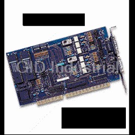
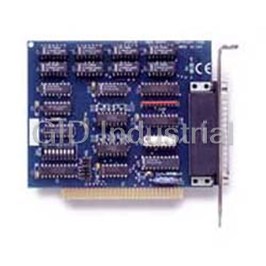
SERIAL I/O - Async, ISA, RS-422/485 Interface, ports: 2, Ultra-SIO
Part Number
3089
Price
Request Quote
Manufacturer
SEALEVEL SYSTEMS
Lead Time
Request Quote
Category
PRODUCTS - 3
Features
- Summary
- The Sealevel Systems ULTRA SIO provides the PC with two Isolated RS-422/485 Asynchronous links to data collection and other devices. Isolation is important in installations where the equipment connect
Datasheet

Extracted Text
Ultra-SIO Users Manual Part # 3089 and 3189 Sealevel Systems, Inc. Telephone: 864.843.4343 155 Technology Place Fax: 864.843.3067 Liberty, SC 29657 USA www.sealevel.com Contents INTRODUCTION........................................................................................................................ 1 OVERVIEW .............................................................................................................................................. 1 WHAT’S INCLUDED ................................................................................................................................. 1 FACTORY DEFAULT SETTINGS ................................................................................................................ 1 CARD SETUP ............................................................................................................................ 2 ADDRESS SELECTION .............................................................................................................................. 2 PORT ENABLE / DISABLE......................................................................................................................... 2 IRQ SELECTION ...................................................................................................................................... 3 INTERRUPT MODES ................................................................................................................................. 3 RS-485 ENABLE MODES......................................................................................................................... 4 INTERFACE MODE EXAMPLES ................................................................................................................. 5 LINE TERMINATION................................................................................................................................. 6 INSTALLATION......................................................................................................................... 7 OPERATING SYSTEM INSTALLATION ....................................................................................................... 7 Windows 95/98/ME/NT/2000/XP....................................................................................................... 7 Linux ................................................................................................................................................... 8 QNX .................................................................................................................................................... 8 TECHNICAL DESCRIPTION....................................................................................................... 9 FEATURES ............................................................................................................................................... 9 CONNECTOR PIN ASSIGNMENTS (DB 9 MALE)..................................................................................... 9 SPECIFICATIONS .................................................................................................................... 10 ENVIRONMENTAL SPECIFICATIONS ....................................................................................................... 10 MANUFACTURING ................................................................................................................................. 10 POWER CONSUMPTION.......................................................................................................................... 10 PHYSICAL DIMENSIONS......................................................................................................................... 10 APPENDIX A - TROUBLESHOOTING ...................................................................................... 11 APPENDIX B - HOW TO GET ASSISTANCE............................................................................ 12 APPENDIX C - ELECTRICAL INTERFACE .............................................................................. 13 RS-422 ................................................................................................................................................. 13 RS-485 ................................................................................................................................................. 13 APPENDIX D - GROUND LOOP PHENOMENON...................................................................... 14 WHAT IS GROUND LOOP? ..................................................................................................................... 14 CABLING RECOMMENDATIONS.............................................................................................................. 14 APPENDIX E - ASYNCHRONOUS COMMUNICATIONS ............................................................ 15 APPENDIX F - SILK-SCREEN ................................................................................................. 16 APPENDIX G - COMPLIANCE NOTICES ................................................................................. 17 FEDERAL COMMUNICATIONS COMMISSION STATEMENT....................................................................... 17 EMC DIRECTIVE STATEMENT............................................................................................................... 17 WARRANTY............................................................................................................................ 18 Figures Figure 1 - Address Selection Table ................................................................................................................... 2 Figure 2 - Header E11 and E12, IRQ Selection ............................................................................................... 3 Figure 3 - Header E5 & E6, Normal IRQ Mode.............................................................................................. 3 Figure 4 - Header E5 & E6, Shared IRQ Mode............................................................................................... 4 Figure 5 - Header E5 & E6, Sharing IRQs with another adapter.................................................................. 4 Figure 6 - RS-422................................................................................................................................................ 5 Figure 7 - RS-485 ‘Auto’ Enabled, with ‘No Echo’ ......................................................................................... 5 Figure 8 - RS-485 ‘Auto’ Enabled, with ‘Echo’............................................................................................... 6 Figure 9 - RS-485 ‘RTS’ Enabled, with ‘No Echo’.......................................................................................... 6 Figure 10 - Headers E1 and E4, Line Termination ......................................................................................... 6 Figure 11 - Ultra-SIO cabling example........................................................................................................... 14 Figure 12 - Asynchronous Communications Bit Diagram............................................................................ 15 © 2003h Sealevel Systems, Incorporated. All rights reserved. Introduction Introduction Overview The Sealevel Systems Ultra-SIO provides the PC with two additional ground isolated RS-422/485 (P/N 3189) or two non-isolated RS-422/485 (P/N 3089) serial ports for terminals, modems, printers, etc. Isolation is important in installations where the equipment being connected to the PC is either far from the PC, or on a different power transformer circuit. Ground loop current is a commonly neglected and misunderstood phenomenon that leads to data loss and the possible destruction of communications interfaces. The isolated Ultra-SIO provides up to 500 volts DC of isolation. What’s Included The Ultra-SIO is shipped with the following items. If any of these items are missing or damaged, contact the supplier. • Ultra-SIO Serial I/O Adapter (P/N 3189 with isolation or P/N 3089 without isolation) • Sealevel Software CD Factory Default Settings The Ultra-SIO factory default settings are as follows: Port # Base Address IRQ Electrical Specification Port 1 3E8 5 RS-422 Port 2 2E8 10 RS-422 To install the Ultra-SIO using factory default settings, refer to Installation on page Error! Bookmark not defined.. For your reference, record installed Ultra-SIO settings below: Port # Base Address IRQ Electrical Specification Sealevel Systems ULTRA-SIO Page 1 Card Setup Card Setup The Ultra-SIO contains several jumper straps that must be set for proper operation. Address Selection Each port on the Ultra-SIO occupies eight consecutive I/O locations. A DIP-switch is used to set the base address for these locations. SW1 sets the I/O address for port 1 and SW2 sets port 2. The following table shows the addressing options available. If different address options are required, please contact Sealevel Systems Technical Support about a custom PAL option. 1 2 3 4 3F8 On On On On 2F8 On On Off On 3E8 On Off On On 2E8 On Off Off On 2A0 Off On On On 300 Off On Off On 328 Off Off On On Disabled Off Off Off Off Figure 1 - Address Selection Table Note: Each COM: port in the system should have a unique address. Typically COM1: - COM4: addresses are 3F8, 2F8, 3E8 and 2E8 Hex. Refer to Appendix A for common address contentions. Port Enable / Disable Each port on the Ultra-SIO can be enabled or disabled with switch position 4 on the DIP-switch. The port is enabled with the switch ‘On’ and disabled when ‘Off’. If any port is disabled, be sure to disable the interrupt request for that port by removing the IRQ jumper. Sealevel Systems ULTRA-SIO Page 2 Card Setup IRQ Selection Headers E11 and E12 select the interrupt request for each serial port. If COM1: is selected, the corresponding jumper must be on the IRQ4 setting. If COM2: is selected, the corresponding jumper must be on IRQ3. Note: Most communications software applications default COM3: to IRQ4 and COM4: to IRQ3. This requires the sharing of interrupts between COM1: and COM3:, and between COM2: and COM4:. While this is the default, it is not always the preferred setting. Check your software configuration instructions to determine the most appropriate IRQ selection. Figure 2 - Header E11 and E12, IRQ Selection Any two or more ports can share a common IRQ by placing the jumpers on the same IRQ setting at header E11 and E12 and setting the appropriate selections at E5 and E6. Note that a polling type driver is needed to share interrupts in this fashion. Windows does not supply a polling type driver. Consult your particular software for IRQ selection. If no interrupt is desired, remove the jumper. Interrupt Modes Header E5 and E6 selects the interrupt mode for each port. Each port must be set in the correct mode to insure proper operation. ‘N’ indicates the (N)ormal, single interrupt per port mode. ‘S’ Indicates the (S)hared interrupt mode, which allows more than one port to access a single IRQ. Any two or more ports can share a common IRQ by placing the jumpers on the same IRQ setting and setting the appropriate selections at E1. Consult your particular software for IRQ selection. If no interrupt is desired, remove the jumper. ‘M’ indicates the inclusion of a 1K ohm pull-down resistor required on one port when sharing interrupts. NS M 1 E5 2 E6 Figure 3 - Header E5 & E6, Normal IRQ Mode Set the jumpers to ‘S’ for shared interrupt mode on all blocks sharing an IRQ except one. Set that port block for ‘M’. This provides the pull-down resistor circuit that makes sharing IRQs possible. If you are using more than one Ultra-SIO or a compatible adapter in a bus you should only have one port set to ‘M’. The following example shows both ports sharing a single IRQ. Sealevel Systems ULTRA-SIO Page 3 15 14 12 11 10 7 6 5 4 3 2/9 Card Setup NS M 1 E5 2 E6 Figure 4 - Header E5 & E6, Shared IRQ Mode Set the jumper to ‘S’ if you are using more than one Ultra-SIO in a bus or to completely remove the pull-down resistor for hardware compatibility. Setting the adapter in this configuration when it is not accompanied by a pull-down resistor will prevent the ports from triggering an interrupt. NS M 1 E5 2 E6 Figure 5 - Header E5 & E6, Sharing IRQs with another adapter RS-485 Enable Modes RS-485 is ideal for multi-drop or network environments. RS-485 requires a tri-state driver (not dual-state) that will allow the electrical presence of the driver to be removed from the line. The driver is in a tri-state or high impedance condition when this occurs. Only one driver may be active at a time and the other driver(s) must be tri-stated. The output modem control signal Request To Send (RTS) is typically used to control the state of the driver. Some communication software packages refer to RS-485 as RTS enable or RTS block mode transfer. One of the unique features of the Ultra-SIO is the ability to be RS-485 compatible without the need for special software or drivers. This ability is especially useful in Windows, Windows NT, and OS/2 environments where the lower level I/O control is abstracted from the application program. This ability means that the user can effectively use the Ultra-SIO in a RS-485 application with existing (i.e. standard RS-232) software drivers. Headers E8 (Port 1) and E10 (Port 2) are used to control the RS-485 mode functions for the driver circuit. The two selections are ‘RTS’ enable or ‘Auto’ enable. The ‘Auto’ enable feature automatically enables/disables the RS-485 interface. The ‘RTS’ mode uses the ‘RTS’ modem control signal to enable the RS-485 interface and provides backward compatibility with existing software products. If you have E3 and E9 in the RS-422 mode and wish to have the RTS signal present at the DB connector place a jumper over the RTS pins at E8 and E10. Otherwise the RTS control signal will not be present at the DB connector. Sealevel Systems ULTRA-SIO Page 4 Card Setup Headers E3 (Port 1) and E9 (Port 2) are used to control the RS-485 enable/disable functions for the receiver circuit and determine the state of the RS-422/485 driver. The RS-485 ‘Echo’ is the result of connecting the receiver inputs to the transmitter outputs. Every time a character is transmitted; it is also received. This can be beneficial if the software can handle echoing (i.e. using received characters to throttle the transmitter) or it can confuse the system if the software does not. These header blocks are described in the illustration and table that follow: 1 No Echo Echo 422 485 E3 = Port 1 E9 = Port 2 Position 1 ‘Echo’ Echoes the data that is transmitted. All characters transmitted are received. (Only relevant in the two wire RS-485 Mode) Position 2 ‘No Echo’ Inhibits the data that has been transmitted. Receiver is off when transmitter is on. (Only relevant in the two wire RS-485 Mode) Position 3 ‘422’ RS-422/485 Driver always enabled (RS-422 Mode). RTS modem control signal available on DB-9 connector. Position 4 ‘485’ RS-422/485 Driver enabled by RTS or ‘Auto’ enabled. Modem control signal not available on DB-9 connector. Interface Mode Examples RTS Auto E8 & E10 E3 & E9 Figure 6 - RS-422 RTS Auto E8 & E10 E3 & E9 Figure 7 - RS-485 ‘Auto’ Enabled, with ‘No Echo’ Sealevel Systems ULTRA-SIO Page 5 Card Setup RTS Auto E8 & E10 E3 & E9 Figure 8 - RS-485 ‘Auto’ Enabled, with ‘Echo’ RTS Auto E8 & E10 E3 & E9 Figure 9 - RS-485 ‘RTS’ Enabled, with ‘No Echo’ Line Termination Typically, each end of the RS-485 bus must have line terminating resistors (RS-422 terminates at the receive end only). A 120 ohm resistor is across each RS-530/422/485 input in addition to a 1K ohm pull-up/pull-down combination that bias the receiver inputs. Headers E1 and E4 allow the user to customize this interface to their specific requirements. Each jumper position corresponds to a specific portion of the interface. If multiple Ultra-SIO adapters are configured in a RS-485 network, only the boards on each end should have jumpers T, P & P ON. Refer to the following table for each position’s operation: Name Function L Connects the TX+ to RX+ for RS-485 two wire operation. T Adds or removes the 120 ohm termination. L Connects the TX- to RX- for RS-485 two wire operation. P Adds or removes the 1K ohm pull-down resistor in the RS-422/RS-485 receiver circuit (Receive data only). P Adds or removes the 1K ohm pull-up resistor in the RS-422/RS- 485 receiver circuit (Receive data only). L T L P P Figure 10 - Headers E1 and E4, Line Termination Sealevel Systems ULTRA-SIO Page 6 Installation Installation Operating System Installation Windows 95/98/ME/NT/2000/XP Do not install the adapter in the machine until the software has been fully installed. 1. Start Windows. 2. Insert the Sealevel Systems CD in to your CD drive. 3. If ‘Auto-Start’ is enabled for this drive the software will automatically launch. 4. Otherwise, point your browser to the ‘Index.htm’ on the root of the CD 5. The next step is to select ‘Install Software’. 6. Select the part number for your adapter from the listing. 7. Select ‘Windows 95/98/ME/NT/2000/XP’ then (depending on the OS version) select the ‘Run from current Location’ or ‘Open’ option. Follow the information presented on the screens that follow. 8. Run the Add/Remove Hardware utility located in Control Panel. Double click the icon to launch the Wizard. When the Choose Hardware Task appears choose Add/Troubleshoot a device. At that point Windows will search for Plug and Play devices. Since the ISA board is not Plug and Play it will not be found. If Windows finds something you were not expecting, cancel that install and click Next. When Choose a Hardware Device appears select Add a new device. Windows will then ask if you want it to search and you select No, I want to select the hardware from a list. Then click Next. After choosing Next you will see Hardware Type. If you are installing a single port serial card select Ports (COM & LPT). If you are installing a multiport serial card, (two or more ports), choose Multi-port serial adapters. Click Next. The Select a Device Driver window will appear. On the left side find Sealevel Systems, Inc. and on the right side of the window select the card type you are installing. 9. Windows will now show a warning message that it could not detect the settings of the device and that you must enter the settings manually. Click OK. The Add New Hardware Wizard Properties window will appear. This window will show the default settings for the I/O address and one IRQ. The one IRQ will mean that you will be sharing one IRQ for all ports on the board for a multi port card. You will only need one IRQ if installing a single port card. Since Windows cannot detect the settings there my be a conflict with another device or the settings shown may be not the settings you wish to use. To change the settings choose Basic configuration 0001 next to the heading Setting based on:. When this configuration is chosen the Resources window will appear with all question marks. Simply choose each Input/Output Range and IRQ and change the settings to match the board settings. Make sure there are no conflicts with other devices that would appear at the bottom of the window under Conflicting device list. After you have either accepted the default settings or changed the settings, the Start Hardware Installation window will appear. Click Next. 10. The next window that may appear will be the Digital Signature Not Found. Do not search for digitally signed software and continue with the installation. The Completing the Add/Remove Hardware Wizard window will appear. You will be given a chance to change the resource settings again at this point if necessary. Choose Finish. At this point you will need to restart your computer. After restarting the Found New Hardware window will appear for each port that you are installing. To confirm that the drivers installed you can now look in Device Manager under Ports (COM &LPT) and each of the ports should show with their corresponding COM number. Sealevel Systems ULTRA-SIO Page 7 Installation Linux Refer to D:\software\seacom\Other\Linux\Linux.serial.readme (where D: = your CDROM driver letter) found on the Sealevel Systems CD. This file contains valuable information on installing your adapter in the various Linux releases. Also in this sub-directory is the Linux SerialHOWTO. This series of files explains typical Linux serial implementations, as well as informing the user to Linux syntax and preferred practices. QNX Refer to D:\software\seacom\Other\QNX6\Install.readme (where D: = your CDROM driver letter) found on the Sealevel Systems CD. This file contains valuable information on installing your adapter in the QNX6 Neutrino OS, as well as the files required to ensure a flawless implementation. Also provided on the Sealevel Systems CD are implementation instructions for QNX4. These are found in D:\software\seacom\Other\QNX4\QNX_COM.txt. Sealevel Systems ULTRA-SIO Page 8 Technical Description Technical Description The Sealevel Systems Ultra-SIO provides the PC with two additional ground isolated RS-422/485 (P/N 3189) or two non-isolated RS-422/485 (P/N 3089) serial ports for terminals, modems, printers, etc. Isolation is important in installations where the equipment being connected to the PC is either far from the PC, or on a different power transformer circuit. Ground loop current is a commonly neglected and misunderstood phenomena that leads to data loss and the destruction of communications interfaces. The Ultra-SIO isolated boards provide up to 500 volts DC of isolation. The Ultra-SIO utilizes the 16550 UART. This chip features programmable baud rate, data format, interrupt control and a 16 byte input and output FIFO. A full array of UART upgrades is also available offering larger FIFO’s. Contact technical support for details. Features • Automatic RS-485 driver enable/disable allows card to appear to be RS-232 requiring no additional drivers • ‘PAL’ option allows for unique OEM address selection • ‘Shareable’ IRQs allow more than one port to share a single IRQ providing a polling type driver is used. • IRQs 2/9-7, 10, 11, 12, 14, 15 supported • 16550 buffered UARTs Standard • 16 Bit address decode allows for easier integration Connector Pin Assignments (DB 9 MALE) Signal Name Pin # Mode GND Ground 5 TX + Transmit Data Positive 4 Output TX- Transmit Data Negative 3 Output RTS+ Request To Send Positive 6 Output RTS- Request To Send Negative 7 Output RX+ Receive Data Positive 1 Input RX- Receive Data Negative 2 Input CTS+ Clear To Send Positive 9 Input CTS- Clear To Send Negative 8 Input Sealevel Systems ULTRA-SIO Page 9 Specifications Specifications Environmental Specifications Specification Operating Storage Temperature 0º to 70º C -50º to 105º C Range (32º to 158º F) (-58º to 221º F) 10 to 90% R.H. 10 to 90% R.H. Humidity Range Non-Condensing Non-Condensing Manufacturing All Sealevel Systems Printed Circuit boards are built to UL 94V0 rating and are 100% electrically tested. These printed circuit boards are solder mask over bare copper or solder mask over tin nickel. Power Consumption +5 VDC Supply line Rating 600 mA Physical Dimensions Board length 7.35 inches (18.67 cm) Board Height including Goldfingers 4.2 inches (10.66 cm) Board Height excluding Goldfingers 3.9 inches (9.91 cm) Sealevel Systems ULTRA-SIO Page 10 Appendix A - Troubleshooting Appendix A - Troubleshooting Sealevel Software is supplied with the Sealevel Systems adapter and may be used in the troubleshooting procedures. Using this software and following these simple steps can eliminate most common problems without the need to call Technical Support. 1. Identify all I/O adapters currently installed in your system. This includes your on-board serial ports, controller cards, sound cards etc. The I/O addresses used by these adapters, as well as the IRQ (if any) should be identified. 2. Configure your Sealevel Systems adapter so that there is no conflict with currently installed adapters. No two adapters can occupy the same I/O address. 3. Make sure the Sealevel Systems adapter is using a unique IRQ. While the Sealevel Systems adapter does allow the sharing of IRQs, many other adapters (i.e. SCSI adapters & on-board serial ports) do not. 4. Make sure the Sealevel Systems adapter is securely installed in a motherboard slot. 5. When running DOS or Windows 3.x refer to the supplied Sealevel Software and this User Manual to verify that the Sealevel Systems adapter is configured correctly. This software contains a diagnostic program ‘SSD’ (D:\software\seacom\Other\DOS\DIAG, where D: = the driver letter of your CDROM drive) will verify if an adapter is configured properly. This diagnostic program is written with the user in mind and is easy to use 6. For Windows95/98/ME/NT/2000, the diagnostic tool ‘WinSSD’ is installed in the SeaCOM folder on the Start Menu during the setup process. First find the ports using the Device Manager, then use ‘WinSSD’ to verify that the ports are functional. 7. Remember that a loopback test is not possible with the ‘No-Echo’ selection enabled. 8. Always use the Sealevel Systems diagnostic software when troubleshooting a problem. This will eliminate any software issues from the equation. Sealevel Systems ULTRA-SIO Page 11 Appendix B - How To Get Assistance Appendix B - How To Get Assistance Please refer to Troubleshooting Guide prior to calling Technical Support. 1. Begin by reading through the Trouble Shooting Guide in Appendix A. If assistance is still needed please see below. 2. When calling for technical assistance, please have your user manual and current adapter settings. If possible, please have the adapter installed in a computer ready to run diagnostics. 3. Sealevel Systems provides an FAQ section on its web site. Please refer to this to answer many common questions. This section can be found at http://www.sealevel.com/faq.asp. 4. Sealevel Systems maintains a web page on the Internet. Our home page address is www.sealevel.com. The latest software updates, and newest manuals are available via our web site. 5. Technical support is available Monday to Friday from 8:00 a.m. to 5:00 p.m. eastern time. Technical support can be reached at (864) 843-4343. Return Authorization Must Be Obtained From Sealevel Systems Before Returned Merchandise Will Be Accepted. Authorization Can Be Obtained By Calling Sealevel Systems And Requesting A Return Merchandise Authorization (RMA) Number. Sealevel Systems ULTRA-SIO Page 12 Appendix C – Electrical Interface Appendix C - Electrical Interface RS-422 The RS-422 specification defines the electrical characteristics of balanced voltage digital interface circuits. RS-422 is a differential interface that defines voltage levels and driver/receiver electrical specifications. On a differential interface, logic levels are defined by the difference in voltage between a pair of outputs or inputs. In contrast, a single ended interface, for example RS-232, defines the logic levels as the difference in voltage between a single signal and a common ground connection. Differential interfaces are typically more immune to noise or voltage spikes that may occur on the communication lines. Differential interfaces also have greater drive capabilities that allow for longer cable lengths. RS-422 is rated up to 10 Megabits per second and can have cabling 4000 feet long. RS-422 also defines driver and receiver electrical characteristics that will allow 1 driver and up to 32 receivers on the line at once. RS-422 signal levels range from 0 to +5 volts. RS-422 does not define a physical connector. RS-485 RS-485 is backwardly compatible with RS-422; however, it is optimized for partyline or multi-drop applications. The output of the RS-422/485 driver is capable of being Active (enabled) or Tri-State (disabled). This capability allows multiple ports to be connected in a multi-drop bus and selectively polled. RS-485 allows cable lengths up to 4000 feet and data rates up to 10 Megabits per second. The signal levels for RS-485 are the same as those defined by RS-422. RS-485 has electrical characteristics that allow for 32 drivers and 32 receivers to be connected to one line. This interface is ideal for multi-drop or network environments. RS-485 tri-state driver (not dual-state) will allow the electrical presence of the driver to be removed from the line. Only one driver may be active at a time and the other driver(s) must be tri-stated. RS-485 can be cabled in two ways, two wire and four wire mode. Two wire mode does not allow for full duplex communication, and requires that data be transferred in only one direction at a time. For half-duplex operation, the two transmit pins should be connected to the two receive pins (Tx+ to Rx+ and Tx- to Rx-). Four wire mode allows full duplex data transfers. RS-485 does not define a connector pin-out or a set of modem control signals. RS-485 does not define a physical connector. Sealevel Systems ULTRA-SIO Page 13 Appendix D - Ground Loop Phenomenon Appendix D - Ground Loop Phenomenon What is Ground Loop? Ground loop Phenomenon occurs when two (or more) pieces of equipment are connected together with a common ground and a different ground potential exists at each location. This current can cause the connected equipment to experience noise that in turn causes data transmission errors. In the extreme this ground current can cause equipment malfunction or even destruction. Cabling Recommendations When connecting the Ultra-SIO in a RS-485 network, care should be taken that both ends of the network are not isolated from ground (see Figure 12). This “floating” ground condition could cause the capacitive or inductive coupling of voltages that will cause a break down in the DC to DC converter circuit or in the opto-isolator circuit. This condition will cause data errors and possibly destruction of the receiver circuit. DATA+ AB DATA- Non Isolated Isolated Ground Ultra SIO Ultra SIO Isolation Barrier Figure 11 - Ultra-SIO cabling example Sealevel Systems ULTRA-SIO Page 14 Appendix E - Asynchronous Communications Appendix E - Asynchronous Communications Serial data communications implies that individual bits of a character are transmitted consecutively to a receiver that assembles the bits back into a character. Data rate, error checking, handshaking, and character framing (start/stop bits) are pre-defined and must correspond at both the transmitting and receiving ends. Asynchronous communications is the standard means of serial data communication for PC compatibles and PS/2 computers. The original PC was equipped with a communication or COM: port that was designed around an 8250 Universal Asynchronous Receiver Transmitter (UART). This device allows asynchronous serial data to be transferred through a simple and straightforward programming interface. Character boundaries for asynchronous communications are defined by a starting bit followed by a pre-defined number of data bits (5, 6, 7, or 8). The end of the character is defined by the transmission of a pre-defined number of stop bits (usually 1, 1.5 or 2). An extra bit used for error detection is often appended before the stop bits. Idle state of Odd, Even line or Remain Idle or 5 to 8 Data Bits Unused next start bit 1 P STOP BIT 0 1 1.5 2 Figure 12 - Asynchronous Communications Bit Diagram This special bit is called the parity bit. Parity is a simple method of determining if a data bit has been lost or corrupted during transmission. There are several methods for implementing a parity check to guard against data corruption. Common methods are called (E)ven Parity or (O)dd Parity. Sometimes parity is not used to detect errors on the data stream. This is refereed to as (N)o parity. Because each bit in asynchronous communications is sent consecutively, it is easy to generalize asynchronous communications by stating that each character is wrapped (framed) by pre-defined bits to mark the beginning and end of the serial transmission of the character. The data rate and communication parameters for asynchronous communications have to be the same at both the transmitting and receiving ends. The communication parameters are baud rate, parity, number of data bits per character, and stop bits (i.e. 9600,N,8,1). Sealevel Systems ULTRA-SIO Page 15 Appendix F - Silk-Screen Appendix F - Silk-Screen 5.2" 4.0" Sealevel Systems ULTRA-SIO Page 16 Appendix G - Compliance Notices Appendix G - Compliance Notices Federal Communications Commission Statement FCC - This equipment has been tested and found to comply with the limits for Class A digital device, pursuant to Part 15 of the FCC Rules. These limits are designed to provide reasonable protection against harmful interference when the equipment is operated in a commercial environment. This equipment generates, uses, and can radiate radio frequency energy and, if not installed and used in accordance with the instruction manual, may cause harmful interference to radio communications. Operation of this equipment in a residential area is likely to cause harmful interference in such case the user will be required to correct the interference at the users expense. EMC Directive Statement Products bearing the CE Label fulfill the requirements of the EMC directive (89/336/EEC) and of the low-voltage directive (73/23/EEC) issued by the European Commission. To obey these directives, the following European standards must be met: EN55022 Class A - “Limits and methods of measurement of radio interference characteristics of information technology equipment” EN55024 – “Information technology equipment Immunity characteristics Limits and methods of measurement”. EN60950 (IEC950) - “Safety of information technology equipment, including electrical business equipment” Warning This is a Class A Product. In a domestic environment, this product may cause radio interference in which case the user may be required to take adequate measures to prevent or correct the interference. Always use cabling provided with this product if possible. If no cable is provided or if an alternate cable is required, use high quality shielded cabling to maintain compliance with FCC/EMC directives. Sealevel Systems ULTRA-SIO Page 17 Warranty Warranty Sealevel's commitment to providing the best I/O solutions is reflected in the Lifetime Warranty that is standard on all Sealevel manufactured products. We are able to offer this warranty due to our control of manufacturing quality and the historically high reliability of our products in the field. Sealevel products are designed and manufactured at its Liberty, South Carolina facility, allowing direct control over product development, production, burn-in and testing. Sealevel Systems, Inc. (hereafter "Sealevel") warrants that the Product shall conform to and perform in accordance with published technical specifications and shall be free of defects in materials and workmanship for life. In the event of failure, Sealevel will repair or replace the product at Sealevel's sole discretion. Failures resulting from misapplication or misuse of the Product, failure to adhere to any specifications or instructions, or failure resulting from neglect or abuse are not covered under this warranty. Warranty service is obtained by delivering the Product to Sealevel and providing proof of purchase. Return authorization must be obtained from Sealevel Systems before returned merchandise will be accepted. Authorization is obtained by calling Sealevel Systems and requesting a Return Merchandise Authorization (RMA) number. The Customer agrees to insure the Product or assume the risk of loss or damage in transit, to prepay shipping charges to Sealevel, and to use the original shipping container or equivalent. Warranty is valid only for original purchaser and is not transferable. Sealevel Systems assumes no liability for any damages, lost profits, lost savings or any other incidental or consequential damage resulting from the use, misuse of, or inability to use this product. Sealevel Systems will not be liable for any claim made by any other related party. This warranty applies to Sealevel manufactured Product. Product purchased through Sealevel but manufactured by a third party will retain the original manufacturer's warranty. Sealevel Systems, Incorporated 155 Technology Place P.O. Box 830 Liberty, SC 29657 USA (864) 843-4343 FAX: (864) 843-3067 www.sealevel.com email: support@sealevel.com Technical Support is available from 8 a.m. to 5 p.m. Eastern time. Monday - Friday Trademarks Sealevel Systems, Incorporated acknowledges that all trademarks referenced in this manual are the service mark, trademark, or registered trademark of the respective company. Ultra-SIO is a trademark of Sealevel Systems, Incorporated. Sealevel Systems ULTRA-SIO Page 18
Frequently asked questions
What makes Elite.Parts unique?

What kind of warranty will the 3089 have?
Which carriers does Elite.Parts work with?
Will Elite.Parts sell to me even though I live outside the USA?
I have a preferred payment method. Will Elite.Parts accept it?


What they say about us
FANTASTIC RESOURCE
One of our top priorities is maintaining our business with precision, and we are constantly looking for affiliates that can help us achieve our goal. With the aid of GID Industrial, our obsolete product management has never been more efficient. They have been a great resource to our company, and have quickly become a go-to supplier on our list!
Bucher Emhart Glass
EXCELLENT SERVICE
With our strict fundamentals and high expectations, we were surprised when we came across GID Industrial and their competitive pricing. When we approached them with our issue, they were incredibly confident in being able to provide us with a seamless solution at the best price for us. GID Industrial quickly understood our needs and provided us with excellent service, as well as fully tested product to ensure what we received would be the right fit for our company.
Fuji
HARD TO FIND A BETTER PROVIDER
Our company provides services to aid in the manufacture of technological products, such as semiconductors and flat panel displays, and often searching for distributors of obsolete product we require can waste time and money. Finding GID Industrial proved to be a great asset to our company, with cost effective solutions and superior knowledge on all of their materials, it’d be hard to find a better provider of obsolete or hard to find products.
Applied Materials
CONSISTENTLY DELIVERS QUALITY SOLUTIONS
Over the years, the equipment used in our company becomes discontinued, but they’re still of great use to us and our customers. Once these products are no longer available through the manufacturer, finding a reliable, quick supplier is a necessity, and luckily for us, GID Industrial has provided the most trustworthy, quality solutions to our obsolete component needs.
Nidec Vamco
TERRIFIC RESOURCE
This company has been a terrific help to us (I work for Trican Well Service) in sourcing the Micron Ram Memory we needed for our Siemens computers. Great service! And great pricing! I know when the product is shipping and when it will arrive, all the way through the ordering process.
Trican Well Service
GO TO SOURCE
When I can't find an obsolete part, I first call GID and they'll come up with my parts every time. Great customer service and follow up as well. Scott emails me from time to time to touch base and see if we're having trouble finding something.....which is often with our 25 yr old equipment.
ConAgra Foods