

 Manufacturers
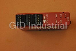
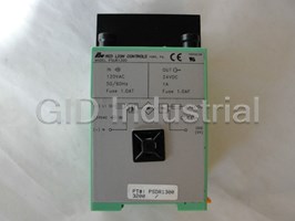
RED LION CONTROLS CSPID2S0
Description
Red Lion Controls CSPID2S0 - Dual Loop Module, Solid State Outputs
Part Number
CSPID2S0
Price
Request Quote
Manufacturer
RED LION CONTROLS
Lead Time
Request Quote
Category
TBD
Specifications
Common Mode Rejection
>110 dB, 50/60 Hz
Normal Mode Rejection
>40 dB, 50/60 Hz
Sample Time
67 msec (15 Hz)
Step Response Time
200 msec typ., 250 msec max
Temperature Coefficient
0.01%/°C
Features
- Auto Addressing minimizes configuration time
- DC analog output (optional, CSPID1 only)
- Fully isolated design provides reliable operation
- Heater current input (optional) ensures detection of heater circuit failure
- Hot swappable replacement reduces downtime
- On demand auto tuning of PID settings
- PID control with reduced overshot
- Universal inputs accept TC, RTD, 0-10 V and 0/4-20 mA signals
- Windows Configuration Software
Datasheet

Extracted Text
Bulletin No. CSPID1-F Drawing No. LP0542 Released 03/09 MODEL CSPID – MODULAR CONTROLLER SERIES PID MODULES DEDICATED SINGLE AND DUAL PID MODULES FOR THE MODULAR CONTROLLER SERIES HOT-SWAPPABLE REPLACEMENT REDUCES DOWNTIME AUTO ADDRESSING MINIMIZES CONFIGURATION TIME FULLY ISOLATED DESIGN PROVIDES RELIABLE OPERATION PID CONTROL WITH REDUCED OVERSHOOT UNIVERSAL INPUTS ACCEPT TC, RTD, 0-10 V and 0/4-20 mA SIGNALS ON DEMAND AUTO-TUNING OF PID SETTINGS DC ANALOG OUTPUT (OPTIONAL, CSPID1 ONLY) HEATER CURRENT INPUT (OPTIONAL) ENSURES DETECTION OF HEATER CIRCUIT FAILURE U ® WINDOWS CONFIGURATION SOFTWARE R C C L US LISTED US LISTED IND. CONT. EQ. 34AD ALARMS GENERAL DESCRIPTION Each loop within the modules has seven internal “soft” alarms, which can be The Model CSPID series modules are full featured PID controllers designed assigned to trigger any output. This includes four process alarms, two heater for use with the Modular Controller Series. The CSPID1 is a single loop current, and one input fault alarm. controller, while the CSPID2 is a dual loop controller. The design of the system provides a true modular PID control platform for multi-zone control applications. The modules can accept a wide range of thermocouple, RTD, 0-10 ANALOG OUTPUT OPTION (CSPID1 ONLY) V, 0/4-20 mA signals. With multiple discrete outputs, plus an optional analog The optional DC Analog Output (10 V or 20 mA) can be independently output (CSPID1 only), the CSPID modules can perform virtually any configured and scaled for control or re-transmission purposes. combination of time-proportioning or linear control for heat, cool, or heat/cool applications. The discrete outputs may also be assigned to one of seven internal HEATER CURRENT MONITOR OPTION soft alarms. The CSPID1’s optional linear output can be assigned to transmit The optional Heater Current Monitor input is useful for early warning of virtually any internal variable. heater degradation, or heater circuit failure. The input connects to a current The CSPID modules connect and communicate via a backplane connection to transformer with an output of 100 mA AC to ensure that proper heater current is the CSMSTR Modular Controller Series Master. The CSMSTR, equipped with present when the control output is on, and that little or no current is present when serial ports as well as an Ethernet port, allows the system to share data with PCs, the output is off. This option provides immediate warning of a circuit short or PLCs, and SCADA systems. The Master supports any combination of up to 16 open, instead of waiting for a high or low temperature shutdown alarm. CS Series modules. The CSPID modules are available with various discrete output combinations, including relays, open drain MOSFETs, and triac outputs. For applications requiring large loads to be controlled, several DIN rail mount relays are available. The modules can operate in On/Off, P, PI, or PID control mode, and use an CAUTION: Risk of Danger. CAUTION: Risk of electric shock. on-demand Auto-Tune that establishes the tuning constants. The PID constants Read complete instructions prior to installation and operation of the unit. may be fine-tuned through the serial or Ethernet interface. The modules employ a unique overshoot suppression feature, which allows the quickest response without excessive overshoot. The modules can also be operated in manual mode, providing the operator with direct control of the output. DIMENSIONS In inches (mm) Internal power management circuits allow the modules to be replaced while power is applied, which reduces downtime in the event of a relay failure. All configuration information is stored locally within each module, as well as in the Master, so replacement modules do not need to be configured. The Modular Controller Series’ high density packaging and DIN rail mounting saves time and panel space. The backplane connection provides power and communication to the module and snaps easily onto standard top hat (T) profile DIN rail. CONFIGURATION ® The Modular Controller Series is configured with Windows compatible ® Crimson software. The software is an easy to use, graphical interface which provides a means of communication configuration, as well as commissioning and calibration of new systems. 1 PROCESS INPUT: SAFETY SUMMARY ACCURACY MAX CONTINUOUS All safety related regulations, local codes and instructions that appear in the INPUT RANGE IMPEDANCE RESOLUTION (18 TO 28 °C) OVERLOAD manual or on equipment must be observed to ensure personal safety and to 10 V 0.1% span 1 M Ohm 50 V 16 bit prevent damage to either the instrument or equipment connected to it. If 20 mA 0.1% span 10 Ohm 100 mA 16 bit equipment is used in a manner not specified by the manufacturer, the protection provided by the equipment may be impaired. 5. TEMPERATURE INDICATION ACCURACY: ± (0.3% of span, +1°C). Do not use the controller to directly command motors, valves, or other Includes NIST conformity, cold junction effect, A/D conversion errors, actuators not equipped with safeguards. To do so can be potentially harmful to temperature coefficient and linearization conformity at 23 °C after 20 minute persons or equipment in the event of a fault to the controller. An independent and warm up. redundant temperature limit indicator with alarm outputs is strongly 6. ISOLATION LEVEL: 500 Vrms @ 50/60 Hz for 1 minute between the recommended. following: OP1 OP2 SPECIFICATIONS OP3 1. POWER: Derived from system backplane. (CSPID1 draws 150 mA max. load OP4 on power input of MASTER, CSPID2 draws 125 mA max). Modules may be Linear Output (CSPID1 only) hot-swapped (Replaced while powered up). Signal Inputs and HCM 2. LEDs*: CS Master Power Supply Input STS - Status LED shows module condition 7. COMMUNICATIONS: Provided by the CS Master OP1, OP2, OP3, OP4 - Indicate status of outputs 1, 2, 3, and 4 8. A/D CONVERTER: 16 bit resolution ALM, or AL1 and AL2 - Alarm LEDs are lit during any internal alarm 9. DISCRETE OUTPUTS: condition CSPID1: Outputs 1 and 2 available as Solid State NFET, Form A relay or * Default configuration. Triac. Output 3 is a Form C relay. 3. MEMORY: Non-volatile memory retains all programmable parameters. CSPID2: Outputs 1 through 4 available as Form A relay, Solid State NFET, MASTER also stores the parameters in order to reprogram modules that are or Triac. replaced. Solid State Output: 4. INPUT: Type: Switched DC, N Channel open drain MOSFET GENERAL: Current Rating: 1 A max Sample Time: 67 msec (15 Hz) VDS ON: 0.3 V @ 1 A Common Mode Rejection: >110 dB, 50/60 Hz VDS MAX: 30 VDC Normal Mode Rejection: >40 dB, 50/60 Hz Offstate Leakage Current: 0.5 mA max Temperature Coefficient: 0.01%/°C Form A Relay Output: Step Response Time: 200 msec typ., 250 msec max Type: N.O. THERMOCOUPLE INPUTS: Current Rating: 3 Amps @ 125 VAC Types: T, E, J, K, R, S, B, N, C 1/10 HP @ 125 VAC Input Impedance: 20 M Ω Life Expectancy: 200,000 cycles at maximum load rating. (Decreasing Lead Resistance Effect: 0.25 µV/Ω load, increasing cycle time, and use of surge suppression such as RC Cold Junction Compensation: Less than ±1°C typical (±1.5°C max) over 0 snubbers increases life expectancy.) to 50 °C ambient temperature Form C Relay Output: Resolution: 0.1° Type: SPDT MEASUREMENT WIRE COLOR TYPE RANGE ANSI BS 1843 Current Rating: 5 Amps @ 125 VAC or 28 VDC (resistive load) -200 to +400°C (+) Blue (+) White 1/8 HP @ 125 VAC T -328 to +752°F (-) Red (-) Blue Life Expectancy: 100,000 cycles at maximum load rating. (Decreasing -200 to +730°C (+) Violet (+) Brown load, increasing cycle time, and use of surge suppression such as RC E -328 to +1346°F (-) Red (-) Blue snubbers increases life expectancy.) -200 to +760°C (+) White (+) Yellow Triac: (CSPID1TA only) J -328 to +1400°F (-) Red (-) Blue Type: Optically isolated, zero-crossing detection -200 to +1250°C (+) Yellow (+) Brown K Rating: 120 VAC, Min: 20 VAC -328 to +2282°F (-) Red (-) Blue Max Load Current: 1.0 A across Operating Temperature Range 0 to +1768°C (+) White R No Standard Min Load Current: 5 mA +32 to +3214°F (-) Blue Offstate Leakage Current: 1 mA Max 0 to +1768°C (+) White S No Standard Operating Frequency: 20 to 400 Hz +32 to +3214°F (-) Blue Protection: Internal Transient Suppression, Fused +149 to +1820°C B No Standard No Standard +300 to +3308°F Triac: (CSPID2T0 and CSPID2TM only) -200 to +1300°C (+) Orange (+) Orange Type: Optically isolated, zero-crossing detection N -328 to +2372°F (-) Red (-) Blue Rating: 120 VAC, Min: 20 VAC C 0 to +2315°C Max Load Current: 0.5A @ 25°C, 0.4A @ 50°C No Standard No Standard W5/W6 +32 to +4199°F Min Load Current: 5 mA mV -5 mV to 56 mV N/A N/A Offstate Leakage Current: 1 mA Max Operating Frequency: 20 to 500 Hz RTD INPUTS: Protection: Internal Transient Suppression, Fused Type: 2 or 3 wire 10. CONTROL MODES: Excitation: 150 µA Control: On/Off, P, PI, or PID Lead Resistance: 15 Ω Max Output: Time proportioning or linear (CSPID1 only) Resolution: 1 or 0.1° Cycle Time: Programmable from 0.0 to 60.0 sec TYPE INPUT TYPE RANGE Auto-Tune: When selected, sets proportional band, integral time, derivative -200 to +600°C 385 100 Ω platinum, Alpha = .00385 time values, and output dampening time -328 to +1100°F -200 to +600°C Probe Break Action: Programmable response 392 100 Ω platinum, Alpha = .003919 -328 to +1100°F Sensor Fail Response: Upscale -80 to +215°C 672 120 Ω nickel, Alpha = .00672 -112 to +419°F 2 11. ALARMS: 15. CERTIFICATIONS AND COMPLIANCES: Modes: SAFETY Manual UL Listed, File # E302106, UL508, CSA C22.2 No. 14-M05 Absolute High Acting LISTED by Und. Lab. Inc. to U.S. and Canadian safety standards Absolute Low Acting IEC 61010-1, EN 61010-1: Safety requirements for electrical equipment Deviation High Acting for measurement, control, and laboratory use, Part 1. Deviation Low Acting ELECTROMAGNETIC COMPATIBILITY Inside Band Acting Emissions and Immunity to EN 61326: 2006: Electrical Equipment for Outside Band Acting Measurement, Control and Laboratory use. Reset Action: Programmable; automatic or latched Immunity to Industrial Locations: Standby Mode: Programmable; enable or disable Electrostatic discharge EN 61000-4-2 Criterion B Hysteresis: Programmable 4 kV contact discharge Sensor Fail Response: Upscale 8 kV air discharge 12. ANALOG DC OUTPUT (optional, CSPID1 only): 3 Electromagnetic RF fields EN 61000-4-3 Criterion B Selectable/programmable for 0-10 VDC, 0-20 mA, or 4-20 mA 10 V/m Resolution: Fast transients (burst) EN 61000-4-4 Criterion B Voltage: 500 µV power 2 kV Current: 1 µA I/O signal 1 kV Accuracy: I/O signal connected to power 2 kV 0.1% of full scale (18 to 28 °C) Surge EN 61000-4-5 Criterion B power 1 kV L-L, 2 kV L-G 0.2% of full scale (0 to 50 °C) Update Time: 0.0 to 60.0 sec signal 1 kV RF conducted interference EN 61000-4-6 Criterion A Compliance (for current output only): 500 Ω max. 3 V/rms Minimum load (voltage output only): 10 KΩ min. Emissions: Outputs are independently jumper selectable for either 10 V or 20 mA. The Emissions EN 55011 Class A output range may be field calibrated to yield approximate 10% overrange and a small underrange (negative) signal. Notes: 13. HEATER CURRENT MONITOR INPUT (optional): 1. Criterion A: Normal operation within specified limits. Type: Single phase, full wave monitoring of load currents 2. Criterion B: Temporary loss of performance from which the unit self- Input: 100 mA max. input for use with external current transformers recovers. Input Resistance: 5 Ω 3. The module’s analog input and/or output signals may deviate during Accuracy: ±3.0% full scale, 5 to 100% of range disturbance but self-recover when disturbance is removed. Frequency: 50 to 400 Hz 4. Power supplied from backplane via Master Module. Minimum output on time for break alarm: 350 msec 16. CONSTRUCTION: Case body is burgundy high impact plastic. Installation 14. ENVIRONMENTAL CONDITIONS: Category I, Pollution Degree 2. Operating Temperature Range: 0 to +50 °C 17. CONNECTIONS: Removable wire clamp screw terminal blocks. Storage Temperature Range: -40 to +85 °C Wire Gage: 28-16 AWG terminal gage wire Operating and Storage Humidity: 85% max relative humidity, non- Torque: 1.96-2.23 inch/lbs (0.22-0.25 N-m) condensing, from 0 to +50°C 18. MOUNTING: Snaps on to standard DIN style top hat (T) profile mounting Vibration According to IEC 68-2-6: 10 to 150 Hz, 0.075 mm amplitude in rails according to EN50022 -35 x 7.5 and -35 x 15. X, Y, Z direction 1 g. 19. WEIGHT: CSPID1: 7 oz (198.4 g) Shock According to IEC 68-2-27: Operational 25 g (10g relay), 11 msec in 3 CSPID2: 7 oz (198.4 g) directions. Altitude: Up to 2000 meters BLOCK DIAGRAM 3 5. In extremely high EMI environments, the use of external EMI suppression EMC INSTALLATION GUIDELINES devices such as Ferrite Suppression Cores for signal and control cables is Although Red Lion Controls Products are designed with a high degree of effective. The following EMI suppression devices (or equivalent) are immunity to Electromagnetic Interference (EMI), proper installation and wiring recommended: methods must be followed to ensure compatibility in each application. The type Fair-Rite part number 0443167251 (RLC part number FCOR0000) of the electrical noise, source or coupling method into a unit may be different TDK part number ZCAT3035-1330A for various installations. Cable length, routing, and shield termination are very Steward part number 28B2029-0A0 important and can mean the difference between a successful or troublesome 6. To protect relay contacts that control inductive loads and to minimize radiated installation. Listed are some EMI guidelines for a successful installation in an and conducted noise (EMI), some type of contact protection network is industrial environment. normally installed across the load, the contacts or both. The most effective 1. A unit should be mounted in a metal enclosure, which is properly connected location is across the load. to protective earth. a. Using a snubber, which is a resistor-capacitor (RC) network or metal oxide a. The mounting clip that connects to the DIN rail should have the DIN rail varistor (MOV) across an AC inductive load is very effective at reducing connected to protective earth. EMI and increasing relay contact life. 2. Use shielded (screened) cables for all Signal and Control inputs. The shield b. If a DC inductive load (such as a DC relay coil) is controlled by a transistor (screen) pigtail connection should be made as short as possible. The switch, care must be taken not to exceed the breakdown voltage of the connection point for the shield depends somewhat upon the application. transistor when the load is switched. One of the most effective ways is to Listed below are the recommended methods of connecting the shield, in place a diode across the inductive load. Most RLC products with solid order of their effectiveness. state outputs have internal zener diode protection. However external diode a. Connect the shield to earth ground (protective earth) at one end where the protection at the load is always a good design practice to limit EMI. unit is mounted. Although the use of a snubber or varistor could be used. b. Connect the shield to earth ground at both ends of the cable, usually when RLC part numbers: Snubber SNUB0000 the noise source frequency is over 1 MHz. Varistor ILS11500 or ILS23000 c. Connect the shield to common of the module and leave the other end of the Note: Reference manufacturer’s instructions when installing any EMI shield unconnected and insulated from earth ground. suppression device. 3. Never run Signal or Control cables in the same conduit or raceway with AC 7. Also care should be taken when connecting input and output devices to the power lines, conductors feeding motors, solenoids, SCR controls, and instrument. When a separate input and output common is provided, they heaters, etc. The cables should be run through metal conduit that is properly should not be mixed. Therefore a sensor common should NOT be connected grounded. This is especially useful in applications where cable runs are long to an output common. This would cause EMI on the sensitive input common, and portable two-way radios are used in close proximity or if the installation which could effect the instruments, operation. is near a commercial radio transmitter. Also, Signal or Control cables within an enclosure should be routed as far away as possible from contactors, Visit RLC’s web site at www.redlion.net for more information on EMI control relays, transformers, and other noisy components. guidelines, Safety and CE issues as they relate to Red Lion Controls products. 4. Long cable runs are more susceptible to EMI pickup than short cable runs. Therefore, keep cable runs as short as possible. HARDWARE CSPID1 ONLY CSPID2 ONLY ANALOG OUTPUT OPTION INPUT JUMPERS Select either Voltage or Current output by placing the output jumpers in the Select the desired input type for each channel by positioning the jumper appropriate location. The output jumpers are located on the side of the CSPID1 appropriately. For thermocouple inputs, the jumper position can be ignored. module. Voltage Current INSTALLATION ATTACH THE MODULE BASE SEPARATE BASE ATTACH MODULE TO BASE TO THE DIN RAIL FROM MODULE 4 WIRING WIRING CONNECTIONS All conductors should meet voltage and current ratings for each terminal. Also, cabling should conform to appropriate standards of good installation, local codes and regulations. When wiring the module, use the numbers on the label to identify the position number with the proper function. Strip the wire, leaving approximately 1/4" (6 mm) of bare wire exposed. Insert the wire into the terminal, and tighten. CSPID1 INPUT CONNECTIONS RTD Voltage Heater Current Monitor Thermocouple and Millivolt Current CSPID2 INPUT CONNECTIONS RTD Voltage Heater Current Monitor Thermocouple and Millivolt Current 5 CSPID1 OUTPUT CONNECTIONS Analog Output Outputs 1 and 2 - Relay Version Output 3 Outputs 1 and 2 - Triac Version Outputs 1 and 2 - Solid State Version CSPID2 OUTPUT CONNECTIONS Outputs 1- 4 - Relay Version Outputs 1- 4 - Solid State Version Outputs 1- 4 - Triac Version 6 Error States LEDS Solid Red Module not controlling, and not communicating. STS – STATUS LED The Status LED is a dual color LED that provides information regarding the Module is controlling properly, but has lost Green/Pulsing Red state of the module. This includes indication of the various stages of the start-up communication with the Master. routine (power-up), as well as any errors that may occur. Startup Routine OP1, OP2, OP3, OP4* – OUTPUT STATUS LED The OP1, OP2, OP3, and OP4* LEDs are factory configured to indicate the Module is currently running the boot loader and/or Rapidly Flashing Red being flash upgraded by Crimson. This occurs for status of the outputs. The LEDs turn on when the output is active. four seconds during a power up. These LEDs may be remapped to various other module properties. *CSPID2 only Steady Red Module switching to configuration. Green Module performing normally. ALM OR AL1 & AL2 – ALARM LED The Alarm LEDs are factory configured to indicate the presence of an alarm. Whenever one of the seven alarms is active, the LED turns on. FIRMWARE UPGRADE These LEDs may be remapped to various other module properties. The module’s firmware is stored in flash memory to prevent software/hardware conflicts, and so that software features may be added in the future. During a download, Crimson compares its own library of firmware files with those stored in the Master module. If they do not match, Crimson will download the necessary files. The Master then checks to make sure that the I/O modules CONFIGURATION contain the same firmware. If they contain a different revision, the Master will ® ® automatically copy those files into the module's flash memory. During this Programming is done via Crimson software, a Windows compatible configuration interface. Please see the Crimson manual for more information. process, the module LEDs will flash rapidly, starting with the top row, and progressing through the remaining rows until the process is complete. ORDERING INFORMATION TYPE MODEL NO. DESCRIPTION PART NUMBER Modular Controller Master, Multi Comms ports and Ethernet CSMSTRV2 Modular Controller Master with multiple protocol converter, CSMSTRLE Ethernet and expansion slot Modular Controller Master with multiple protocol converter, data Master Module CSMSTR logger, web server with Virtual HMI up to QVGA (320 x 240) size CSMSTRSX and expansion slot. Modular Controller Master with multiple protocol converter, data logger, web server with Virtual HMI up to VGA (640 x 480) size CSMSTRGT and expansion slot with increased SDRAM Single Loop Module, Relay Outputs CSPID1R0 Single Loop Module, Relay Outputs, Analog Output CSPID1RA Single Loop Module, Relay Outputs, Heater Current Input CSPID1RM 1 Single Loop Module, Solid State Outputs CSPID1S0 CSPID1 Single Loop Module, Solid State Outputs, Analog Output CSPID1SA Single Loop Module, Solid State Outputs, Heater Current Input CSPID1SM PID Control Modules Single Loop Module, Triac Outputs, Analog Output CSPID1TA Dual Loop Module, Relay Outputs CSPID2R0 Dual Loop Module, Relay Outputs, Heater Current Input CSPID2RM Dual Loop Module, Solid State Outputs CSPID2S0 CSPID2 Dual Loop Module, Solid State Outputs, Heater Current Input CSPID2SM Dual Loop Module, Triac Outputs CSPID2T0 Dual Loop Module, Triac Outputs, Heater Current Input CSPID2TM Communications Programming Cable for CS, G3, & Paradigm Series CBLPROG0 Cables CBL 1 Communications Cables CBLxxxxx (10 feet) ® 2 SFCRM Crimson Programming Software Software ® Crimson Programming Software, Manual, and Download Cable SFCRK Rail Stops (Qty 2) RSRSTP00 Accessories Replacement Base CSBASE00 Replacement Termination Plug CSTERM00 1 Visit www.redlion.net for a complete list of PID modules, data acquisition modules, communications drivers and cables. 2 Free at www.redlion.net 7 LIMITED WARRANTY The Company warrants the products it manufactures against defects in materials and workmanship for a period limited to two years from the date of shipment, provided the products have been stored, handled, installed, and used under proper conditions. The Company’s liability under this limited warranty shall extend only to the repair or replacement of a defective product, at The Company’s option. The Company disclaims all liability for any affirmation, promise or representation with respect to the products. The customer agrees to hold Red Lion Controls harmless from, defend, and indemnify RLC against damages, claims, and expenses arising out of subsequent sales of RLC products or products containing components manufactured by RLC and based upon personal injuries, deaths, property damage, lost profits, and other matters which Buyer, its employees, or sub-contractors are or may be to any extent liable, including without limitation penalties imposed by the Consumer Product Safety Act (P.L. 92-573) and liability imposed upon any person pursuant to the Magnuson-Moss Warranty Act (P.L. 93-637), as now in effect or as amended hereafter. No warranties expressed or implied are created with respect to The Company’s products except those expressly contained herein. The Customer acknowledges the disclaimers and limitations contained herein and relies on no other warranties or affirmations.
Frequently asked questions
What makes Elite.Parts unique?

What kind of warranty will the CSPID2S0 have?
Which carriers does Elite.Parts work with?
Will Elite.Parts sell to me even though I live outside the USA?
I have a preferred payment method. Will Elite.Parts accept it?
Why buy from GID?

Quality
We are industry veterans who take pride in our work

Protection
Avoid the dangers of risky trading in the gray market

Access
Our network of suppliers is ready and at your disposal

Savings
Maintain legacy systems to prevent costly downtime

Speed
Time is of the essence, and we are respectful of yours
Related Products
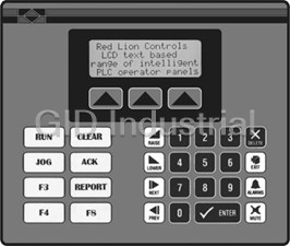
Red Lion Controls CL200010 4 x 20 LCD Operator Interface Terminal
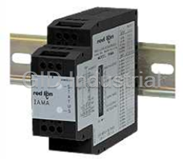
Red Lion Controls IAMA6262 Universal Signal Conditioning Module
Red Lion Controls IMP20060 Meter - METER BASE UNIT 115/230

Red Lion Controls PRS10011 Speed Switch - Plug-in, 0.1-1HZ, 115VAC
Red Lion Controls PSDR-1300 POWER SUPPLY DIN RAIL MOUNT 120VAC/24VDC 1AMP
Red Lion Controls VX500TS0 Operator Interface Panels. 640 x 480 | 16 Color | Touchscreen | 736K Mem.
Request a Quote

The quote request has been received
Close

Facing challenges or have inquiries? Feel free to contact us!
Call Us +1-469-283-2440
What they say about us
FANTASTIC RESOURCE
One of our top priorities is maintaining our business with precision, and we are constantly looking for affiliates that can help us achieve our goal. With the aid of GID Industrial, our obsolete product management has never been more efficient. They have been a great resource to our company, and have quickly become a go-to supplier on our list!
Bucher Emhart Glass
EXCELLENT SERVICE
With our strict fundamentals and high expectations, we were surprised when we came across GID Industrial and their competitive pricing. When we approached them with our issue, they were incredibly confident in being able to provide us with a seamless solution at the best price for us. GID Industrial quickly understood our needs and provided us with excellent service, as well as fully tested product to ensure what we received would be the right fit for our company.
Fuji
HARD TO FIND A BETTER PROVIDER
Our company provides services to aid in the manufacture of technological products, such as semiconductors and flat panel displays, and often searching for distributors of obsolete product we require can waste time and money. Finding GID Industrial proved to be a great asset to our company, with cost effective solutions and superior knowledge on all of their materials, it’d be hard to find a better provider of obsolete or hard to find products.
Applied Materials
CONSISTENTLY DELIVERS QUALITY SOLUTIONS
Over the years, the equipment used in our company becomes discontinued, but they’re still of great use to us and our customers. Once these products are no longer available through the manufacturer, finding a reliable, quick supplier is a necessity, and luckily for us, GID Industrial has provided the most trustworthy, quality solutions to our obsolete component needs.
Nidec Vamco
TERRIFIC RESOURCE
This company has been a terrific help to us (I work for Trican Well Service) in sourcing the Micron Ram Memory we needed for our Siemens computers. Great service! And great pricing! I know when the product is shipping and when it will arrive, all the way through the ordering process.
Trican Well Service
GO TO SOURCE
When I can't find an obsolete part, I first call GID and they'll come up with my parts every time. Great customer service and follow up as well. Scott emails me from time to time to touch base and see if we're having trouble finding something.....which is often with our 25 yr old equipment.
ConAgra Foods