

 Manufacturers
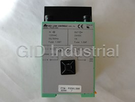
RED LION CONTROLS PRS10011

Description
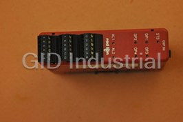
Red Lion Controls PRS10011 Speed Switch - Plug-in, 0.1-1HZ, 115VAC
Part Number
PRS10011
Price
Request Quote
Manufacturer
RED LION CONTROLS
Lead Time
Request Quote
Category
TBD
Specifications
FREQUENCY RANGES AVAILABLE
Available in 5 ranges, each range providing a relay pick-up or drop-out adjustment span of 10:1.
OPERATING TEMPERATURE RANGE
0 to 60°C.
RELAY CONTACT OUTPUT
FORM “C” (SPDT) contacts max. rating 5 amps @ 120/240 VAC or 28 VDC (resistive load), 1/8 H.P. @ 120 VAC (inductive load). The operate time is 5 msec nominal and the release time is 3 msec nominal.
RELAY LIFE EXPECTANCY
100,000 cycles at max. rating. (As load level decreases, life expectancy increases.)
RESPONSE TIME
Response time is equivalent to the period of set-point frequency, plus 5 msec for relay pickup or plus 3 msec for relay dropout.
SENSOR OUTPUT POWER
+12 VDC ±5% regulated, 60 mA max.
WEIGHT
PRS1 PLUG-IN MODULE - 8 oz (226.8 g).
Features
- 4 OPERATING MODES
- LED RELAY “ON” INDICATOR
- OVER-SPEED, UNDER-SPEED, OR ZERO-SPEED DETECTION
- PROGRAMMABLE INPUT CIRCUIT ACCEPTS OUTPUTS FROM A VARIETY OF SENSORS
- RANGES, FROM 0.1 Hz to 10 KHz
- REPEATABILITY TO 1/2% OF MAX. RANGE
Datasheet

Extracted Text
Bulletin No. PRS1-H Drawing No. LP0026 Released 8/05 Tel +1 (717) 767-6511 Fax +1 (717) 764-0839 www.redlion.net MODEL PRS1 - PLUG-IN SPEED SWITCH z 5 RANGES, FROM 0.1 Hz to 10 KHz z OVER-SPEED, UNDER-SPEED, OR ZERO-SPEED DETECTION z 4 OPERATING MODES z REPEATABILITY TO 1/2% OF MAX. RANGE z LED RELAY “ON” INDICATOR z PROGRAMMABLE INPUT CIRCUIT ACCEPTS OUTPUTS FROM A VARIETY OF SENSORS DESCRIPTION SPECIFICATIONS The PRS1 is a versatile, reliable and economical solution to most machine 1. PRIMARY SUPPLY VOLTAGE: Available for 115 or 230 VAC ±10%, speed switching problems. It is not affected by overspeeding and will operate in 50/60 Hz; 2.5 VA (See Ordering Information). either direction of rotation. 2. SENSOR OUTPUT POWER: +12 VDC ±5% regulated, 60 mA max. The heart of the PRS1 is a solid-state CMOS logic circuit, that continuously 3. SIGNAL INPUT CHARACTERISTICS: See “PRS1 Input Circuits, measures the elapsed time between successive trailing edges (negative going) of Sensor Connections & Configuration Switch Set-ups” section. an incoming pulse train or waveform. It compares this time with an adjustable 4. FREQUENCY RANGES AVAILABLE: Available in 5 ranges, each range set-point reference and determines if the period of the waveform is longer providing a relay pick-up or drop-out adjustment span of 10:1. (See Ordering (underspeed) or shorter (overspeed) than the set-point reference. Information) The internal relay is energized during “normal” operation and can be set to 5. RELAY CONTACT OUTPUT: FORM “C” (SPDT) contacts max. rating 5 de-energize on either under or overspeed by a programming switch. The unit amps @ 120/240 VAC or 28 VDC (resistive load), 1/8 H.P. @ 120 VAC can be connected for simple over or underspeed detection or for latch/trip-off (inductive load). The operate time is 5 msec nominal and the release time is operation in a machine STOP/START circuit. 3 msec nominal. The PRS1 features built-in hysteresis (differential between pick-up and drop- 6. RELAY LIFE EXPECTANCY: 100,000 cycles at max. rating. (As load out) of 5% of set-point speed. This prevents the output relay from chattering level decreases, life expectancy increases.) when operating at or near the set-point speed. The set-point control is a 20-turn 7. RESPONSE TIME: Response time is equivalent to the period of set-point screwdriver adjustment accessible at the top of the unit with a 10:1 adjustment frequency, plus 5 msec for relay pickup or plus 3 msec for relay dropout. range. An LED indicates when the relay is energized. A built-in +12 VDC 8. OPERATING TEMPERATURE RANGE: 0 to 60°C. regulated power supply, furnished power for the internal circuit and for external 9. WEIGHT: PRS1 PLUG-IN MODULE - 8 oz (226.8 g). sensor excitation. The plug-in module mates with a heavy duty, CSA approved base mounting WARNING: SPEED SWITCHES MUST NEVER BE USED AS PRIMARY PROTECTION AGAINST HAZARDOUS OPERATING CONDITIONS. socket with pressure clamp screw terminals that accept stripped wires without Machinery must first be made safe by inherent design, or the installation of lugs. Closed back construction allows mounting directly on metal panel without guards, shields, or other devices to protect personnel in the event of a an insulation barrier. hazardous machine speed condition. Then a speed switch may be installed to help prevent the machine from entering the unsafe speed condition. DIMENSIONS In inches (mm) 1 3. ERRATIC OR IRREGULAR SHAFT MOTION PRS1 APPLICATIONS Since the PRS1 operates by timing each successive signal cycle, relay chatter The following guidelines and considerations will help to assure the best can be experienced when the set-point speed is adjusted close to the running performance when applying the PRS1 Speed Switch. speed and the motion of the sensor shaft is irregular. For example, if a sensor 1. SENSOR AND FREQUENCY RANGE SELECTION detects teeth of the driven sprocket in a chain drive with a good deal of chain (See “PRS1 Sensor & Frequency Range Selection” section.) slack, the period between adjacent signal cycles can vary as much as 2:1 as the 2. RESPONSE TIME driven sprocket alternately overhauls and takes up slack. This does not present The PRS1 has an internal adjustable timer whose “time-out” period is a problem if the set-point is adjusted at 5 or 10% of running speed, but if the determined by the set-point adjustment. In operation, this timer is reset set-point is to be 90% of running speed, the PRS1 output will chatter as the (retriggered) at the start of each signal cycle and the internal logic circuitry chain picks up and gives out slack. Again, the solution to this problem is to monitors whether the signal cycle concludes before time-out occurs locate the sensor at a point in the drive train where the motion is smooth. (overspeed) or if time-out occurs before conclusion of the signal cycle Note: The PRS1 has built-in hysteresis of 5% of set-point speed, i.e. underspeed (underspeed). This operating scheme results in an inherent delay in output output occurs at 95% of the overspeed set-point. This allows a set-point near switching response which is insignificant at moderate and higher frequencies, running speed provided shaft motion is reasonably smooth. but can be appreciable at low frequencies. For example, with the PRS10011 4. OVERSPEED OPERATION AND HI-FREQUENCY SENSOR (Range 0.1 to 1 Hz) set to the minimum range, underspeed output will not DROPOUT occur until 10 sec after the initiation of the last signal cycle. Overspeed All ranges of PRS1 units can be operated in the overspeed condition up response is directly related to the period of the signal frequency and will be through 10 KHz without experiencing operational discontinuities. However, faster, depending on the amount of overspeed. when subject to higher input signal frequencies (12 to 15 KHz), signal roll- The inherent delay at low frequencies can be an advantage when the PRS1 is off will occur in the input circuit and the output will transfer to underspeed applied as a zero-speed switch. However, for fast response, a higher as if the signal had dropped to zero frequency. frequency unit with an appropriate sensor arrangement should be used. This Sensor signal drop-out at high frequencies will also cause a false underspeed can often be accomplished simply by moving the sensor to a higher speed output. Caution is advised when selecting proximity, photo-electric, and other shaft, or by going directly to the drive motor shaft with an ARCJ Ring Sensor sensors that have limited high frequency ratings, to ensure that their maximum Kit. (See Sensor Section of the RLC Catalog.) output frequency limit is not exceeded at maximum machine speed. OPERATING MODES MODE A: LOW SPEED OPERATE, OVERSPEED Internal relay is energized at all speeds below the set-point speed, and de-energizes when speed exceeds the set-point speed. Relay again energizes when speed drops approximately 5% below the set-point speed. MODE B: HIGH SPEED OPERATE, UNDERSPEED DROPOUT Internal relay is de-energized at all speeds below the set- point speed, and energizes when the speed exceeds the set- point. The relay again de-energizes when the speed drops approximately 5% below the set-point. MODE C: LATCH, HIGH SPEED OPERATE, UNDERSPEED DROPOUT Pushing the Start button energizes the internal relay and starts the machine. When operating speed is reached, the relay stays latched with the Start button released. If the machine speed drops below the set-point, the relay unlatches, sounding the alarm and stopping the machine. MODE D: LATCH, LOW SPEED OPERATE, OVERSPEED DROPOUT Pushing the Start button energizes and latches the relay and starts the machine. The relay stays latched as long as machine operates below set-point speed. If the machine exceeds the set-point speed, the relay unlatches, sounding the alarm and stopping the machine. ORDERING INFORMATION PART NUMBERS FOR AVAILABLE SUPPLY VOLTAGES MODEL NO. DESCRIPTION A.C. POWER 0.1-1 Hz 1-10 Hz 10-100 Hz 100-1 KHz 1 K-10 KHz 115 VAC PRS10011 PRS10101 PRS11011 PRS11021 PRS11031 PRS1 Speed Switch 230VAC PRS10012 PRS10102 PRS11012 PRS11022 PRS11032 __ Socket, 12-Pin 2300200 2 PRS1 INPUT CIRCUITS, SENSOR CONNECTIONS & CONFIGURATION SWITCH SET-UP The Model PRS1 Speed Switch uses the circuit shown on the right. The circuit uses a comparator amplifier connected as a Schmidt trigger circuit to convert the input wave form into the pulse form required for proper circuit operation. Three set-up switches are used to configure the input circuit to accept signals from a wide variety of sources, as follows: S1 - ON: Connects a 1 K pull-down resistor for sensors with sourcing output. (Maximum sensor output current is 12 mA @ 12 V output.) S2 - ON: Sets bias of input to trigger at V = 2.5 V, V = 3.0 V; for logic level IL IH signals. OFF: Sets the bias of input to trigger at V = 0.25 V, V = 0.75 V; for IL IH increased sensitivity when used with magnetic pickups. S3 - ON: Connects a 3.9 K pull-up resistor for sensors with current sinking output. (Maximum sensor current is 3 mA.) Paralleling With a Counter and/or Rate Indicator Inputs: The PRS1 can be OTHER CHARACTERISTICS & SPECIFICATIONS operated from a common sensor with current sinking output that is also used Maximum Operating Frequency: 10 KHz with maximum pulse width ON to drive the input of a Counter or Rate Indicator. Connect Pin 8 to the and OFF times of 50 µsec. Common Terminal and Pin 7 to the Input Terminal of the Counter or Rate Maximum Input Voltage: Pin 7 (Input) may be driven from an external voltage Indicator; set S1 and S3 “OFF” and S2 “ON”. DO NOT PARALLEL up to ±90 V provided S1 and S3 are “OFF” to disconnect internal load CONNECT THE +12V OUTPUTS (Pin 9) OF PRS1 UNITS WITH THE resistors. (Maximum Input Voltage with S1 “ON” is ±16 V) +12V OUTPUTS OF COUNTERS, DITAKS, OR OTHER PRS1 OR PRA2 Input Impedance: With S1 and S3 “OFF”, the resistive input impedance UNITS. These units have regulated supplies that will not load-share. Multiple exceeds 1 Megohm, as long as Pin 7 voltage is greater than zero and less inputs cannot be operated from sensing switches, 2-wire proximity sensors, than +12 V. or magnetic pickups. CONNECTIONS & CONFIGURATION SWITCH SET-UP FOR VARIOUS SENSOR OUTPUTS MAGNETIC PICKUPS SENSORS WITH CURRENT SINK OUTPUT (NPN O.C.) RLC SENSOR MODELS: ASTC, LMPC, PSAC, LSC, RPGC, RPGB, RPGH, RPGQ, HESS, etc. RECOMMENDED RULES FOR MAGNETIC PICKUP CONNECTIONS 1. Mount the PRS1 in a relatively “noise-free” environment, away from motor starters, SENSORS WITH CURRENT SOURCE OUTPUT (PNP O.C.) control relays, or other sources of electrical interference. 2. Use 2-wire shielded cable for magnetic pickup signal leads. 3. Never run signal cable in conduit, troughs, or cable bundles with power carrying conductors. 4. Connect the shield to the common Terminal “8” at the input of the PRS1. DO NOT connect the shield at the pickup end, leave it “open” and insulate the exposed shield to prevent electrical contact with the frame or case. (Shielded cable, supplied on some RLC magnetic pickups, has open shield on pickup end.) 2-WIRE PROXIMITY SENSORS A.C. INPUTS FROM INVERTERS, A.C. SWITCH CONTACT INPUT TACHOMETERS GENERATORS, ETC. R - Resistor to limit input current to 5 mA peak C - Filter cap required when input A.C. has “ringing” RLC SENSORS WITH -EF OUTPUT characteristics as with inverters. The addition of two external resistors and a capacitor allows the PRS1 to be operated from input signals A.C. Power sources exceeding 50 V output generated by a switch contact. The external RC network should be coupled with an isolation transformer. forms a Low-Pass Filter which operates in conjunction with the hysteresis of the input circuit to “De-bounce” the INPUT FROM CMOS OR TTL Switch Contact signal. Use of the Low-Pass RC Filter places a high-speed restriction on the circuit, and it cannot be used at frequencies of more than 200 to 300 cps. However, Switch Contact input is normally limited to low speed operation, so this does not impose a serious restriction. RLC SENSOR MODEL: LMPEC 3 PRS1 SENSOR & FREQUENCY RANGE SELECTION The PRS1 Speed-Switch normally operates from a variable frequency signal INTERMEDIATE SHAFT SPEEDS (10-1000 RPM) - Magnetic Pickups, the supplied by a machine mounted sensor. The sensor signal varies in frequency in LMPC, RPG’s and some Proximity Sensors are appropriate at these speeds. direct proportion to machine speed, and may be a sinusoidal, triangular, square, HIGH-SHAFT SPEEDS (1000 RPM and up) - Magnetic Pickups, the LMPC or pulse-type waveform. The sensor arrangement can take a variety of forms and RPG’s are usually the best choices. such as a Magnetic Pickup or Proximity Sensor detecting passing teeth on a FOR LINEAR SPEEDS ON PAPER WEBS, TEXTILE, RIBBON, STRIP sprocket or gear, a Photo-Electric Scanner viewing passing pulley spokes, a AND WIRE - The LSC Length Sensor may prove desirable. Rotary Pulse Generator coupled to a machine shaft, or a Length Sensor driven CAUTION: When selecting a sensor for operation at any speed, make sure the by a web or ribbon of material passing through the machine. (See Sensor sensor is also capable of delivering an output for the entire speed range up Section of the catalog for more information on sensors.) through maximum machine speed. Since the PRS1 operates from the frequency content of the incoming signal, the response time of both devices is also related to the signal frequency. This DETERMINING SENSOR FREQUENCY OUTPUT & gives rise to the cardinal rule of selecting a sensor arrangement: SELECTING THE PROPER FREQUENCY RANGE WHEN RESPONSE TIME IS IMPORTANT, SELECT A SENSOR Machine speeds are normally expressed in revolutions/minute (RPM) while ARRANGEMENT & LOCATION THAT WILL PROVIDE A HIGH the PRS1 has adjustable frequency ranges in cycles/second or Hz. In addition, FREQUENCY OUTPUT AT OPERATING SPEED. sensor arrangements usually deliver a number of signal cycles or pulses for When a PRS1 application is first contemplated, it seems to be natural to think each shaft revolution. The following formula provides a convenient way to in terms of applying the sensor to the low speed end of the power drive train. In relate these variables: some cases this may be the only practical location for the sensor, and if fast RPM x PPR FRQ (CPS or Hz) = response is needed from the PRS1, a sensor arrangement capable of delivering 60 a high number of cycles or pulses/revolution (PPR) will be required. In a great WHERE: number of applications however, generating a higher frequency sensor signal is RPM is the speed of the shaft where the sensor is located in revolutions simply a matter of locating the sensor on a intermediate or high speed shaft such per minute. as directly on the drive motor shaft. PPR is the number of pulses (or cycles) produced by the sensor for one Another advantage of moving the sensor location up toward the high speed shaft revolution. end of the drive train is that the shaft rotary motion is usually much smoother and more regular. Slow speed shafts will often rotate irregularly due to gear EXAMPLE 1 backlash, “slop” in couplings, or slack in chain drives. This irregular motion can have an adverse effect on the resulting output, especially when using the A machine is to be equipped with a PRS1 Speed Switch. A 42-tooth timing belt pulley is available in the power drive train, and an LMPC is to be used to PRS1 to perform a speed switching function near normal running speed. sense passing teeth. The PRS1 set-point is to be adjusted to provide overspeed output when the timing belt pulley reaches 730 RPM. What should the SELECTING AN APPROPRIATE SENSOR ARRANGEMENT frequency range of the PRS1 be? There are no exact rules governing the selection of a sensor arrangement since machine geometry and conditions can vary widely from one application 730 RPM x 42 PPR FRQ @ set-point = = 511 Hz to the next. However, the following generalized criteria will prove useful as 60 guidelines toward selecting the best sensor arrangement. (See Sensor Section of SELECT: PRS11021 (or PRS11022 for 230 VAC) which has an adjustable the catalog for more information.) range of 100-1000 Hz. ULTRA-LOW SHAFT SPEEDS (10 RPM or less) - Proximity Sensors, Photo- Electric Scanners, or Rotary Pulse Generators, are usually the best selections. In most ultra-low speed applications, it is advisable to provide as many pulses per revolution as possible (high PPR) to get acceptable response times. LOW-SHAFT SPEEDS (10-100 RPM) - LMPC (Super-Sensitive Magnetic Pickup), Proximity Sensors, Photo-Electric Scanners and RPG’s can usually be applied in this speed range. LIMITED WARRANTY The Company warrants the products it manufactures against defects in materials and workmanship for a period limited to two years from the date of shipment, provided the products have been stored, handled, installed, and used under proper conditions. The Company’s liability under this limited warranty shall extend only to the repair or replacement of a defective product, at The Company’s option. The Company disclaims all liability for any affirmation, promise or representation with respect to the products. The customer agrees to hold Red Lion Controls harmless from, defend, and indemnify RLC against damages, claims, and expenses arising out of subsequent sales of RLC products or products containing components manufactured by RLC and based upon personal injuries, deaths, property damage, lost profits, and other matters which Buyer, its employees, or sub-contractors are or may be to any extent liable, including without limitation penalties imposed by the Consumer Product Safety Act (P.L. 92-573) and liability imposed upon any person pursuant to the Magnuson-Moss Warranty Act (P.L. 93-637), as now in effect or as amended hereafter. No warranties expressed or implied are created with respect to The Company’s products except those expressly contained herein. The Customer acknowledges the disclaimers and limitations contained herein and relies on no other warranties or affirmations. Red Lion Controls AP Red Lion Controls Red Lion Controls BV 31, Kaki Bukit Road 3, 20 Willow Springs Circle Basicweg 11b #06-04/05 TechLink York PA 17402 NL - 3821 BR Amersfoort Singapore 417818 Tel +1 (717) 767-6511 Tel +31 (0) 334 723 225 Tel +65 6744-6613 Fax +1 (717) 764-0839 Fax +31 (0) 334 893 793 Fax +65 6743-3360
Frequently asked questions
What makes Elite.Parts unique?

What kind of warranty will the PRS10011 have?
Which carriers does Elite.Parts work with?
Will Elite.Parts sell to me even though I live outside the USA?
I have a preferred payment method. Will Elite.Parts accept it?
Why buy from GID?

Quality
We are industry veterans who take pride in our work

Protection
Avoid the dangers of risky trading in the gray market

Access
Our network of suppliers is ready and at your disposal

Savings
Maintain legacy systems to prevent costly downtime

Speed
Time is of the essence, and we are respectful of yours
Related Products
Red Lion Controls CL200010 4 x 20 LCD Operator Interface Terminal
Red Lion Controls CSPID2S0 - Dual Loop Module, Solid State Outputs
Red Lion Controls IAMA6262 Universal Signal Conditioning Module
Red Lion Controls IMP20060 Meter - METER BASE UNIT 115/230
Red Lion Controls PSDR-1300 POWER SUPPLY DIN RAIL MOUNT 120VAC/24VDC 1AMP
Red Lion Controls VX500TS0 Operator Interface Panels. 640 x 480 | 16 Color | Touchscreen | 736K Mem.
Request a Quote

The quote request has been received
Close

Facing challenges or have inquiries? Feel free to contact us!
Call Us +1-469-283-2440
What they say about us
FANTASTIC RESOURCE
One of our top priorities is maintaining our business with precision, and we are constantly looking for affiliates that can help us achieve our goal. With the aid of GID Industrial, our obsolete product management has never been more efficient. They have been a great resource to our company, and have quickly become a go-to supplier on our list!
Bucher Emhart Glass
EXCELLENT SERVICE
With our strict fundamentals and high expectations, we were surprised when we came across GID Industrial and their competitive pricing. When we approached them with our issue, they were incredibly confident in being able to provide us with a seamless solution at the best price for us. GID Industrial quickly understood our needs and provided us with excellent service, as well as fully tested product to ensure what we received would be the right fit for our company.
Fuji
HARD TO FIND A BETTER PROVIDER
Our company provides services to aid in the manufacture of technological products, such as semiconductors and flat panel displays, and often searching for distributors of obsolete product we require can waste time and money. Finding GID Industrial proved to be a great asset to our company, with cost effective solutions and superior knowledge on all of their materials, it’d be hard to find a better provider of obsolete or hard to find products.
Applied Materials
CONSISTENTLY DELIVERS QUALITY SOLUTIONS
Over the years, the equipment used in our company becomes discontinued, but they’re still of great use to us and our customers. Once these products are no longer available through the manufacturer, finding a reliable, quick supplier is a necessity, and luckily for us, GID Industrial has provided the most trustworthy, quality solutions to our obsolete component needs.
Nidec Vamco
TERRIFIC RESOURCE
This company has been a terrific help to us (I work for Trican Well Service) in sourcing the Micron Ram Memory we needed for our Siemens computers. Great service! And great pricing! I know when the product is shipping and when it will arrive, all the way through the ordering process.
Trican Well Service
GO TO SOURCE
When I can't find an obsolete part, I first call GID and they'll come up with my parts every time. Great customer service and follow up as well. Scott emails me from time to time to touch base and see if we're having trouble finding something.....which is often with our 25 yr old equipment.
ConAgra Foods