

 Manufacturers
RADISYS EPC-2100

Description
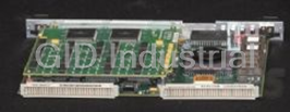
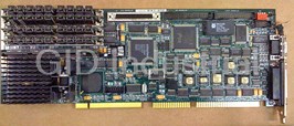
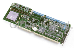
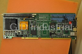
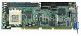
Radisys EPC-2100 Full Size Single Board Computer - Intel Pentium, Intel 430HX, VGA, SCSI and IDE
Part Number
EPC-2100
Price
Request Quote
Manufacturer
RADISYS
Lead Time
Request Quote
Category
PCI/ISA BOARDS
Specifications
Chipset
Intel 430HX PCIset
Flash Memory
4MB (512KB x 8)
Processor
Intel Pentium 100/133/166 MHz, 64-bit Classic Pentium (P54C)
Real Time Clock
DS1687 compatible module with embedded battery
Serial Ports
x2, one RS-232 only; one RS-232 or RS-422
Features
- Floppy drive controller
- Four 256 KB x 16 on-board video DRAM modules (2 MB)
- Four SIMM sockets for up to 256 MB scalable DRAM
- Level 2 write-back cache socket for 256 or 512 KB pipeline burst COAST SRAM
- Parallel port (AT-compatible / bi-directional / EPP)
- PCI EIDE hard disk drive controller
- PS/2 mouse and keyboard connectors
- VGA video connector on the I/O bracket
Datasheet

Extracted Text
SERVICE MANUAL
®
EPC -2100/EPC-2101
PV5000HX2(-IDE) Series SBC
P/N 007-01246-0000 June 2001
© 2001 RadiSys Corporation
All Rights Reserved
Printed in USA
EPC-2100 and EPC-2101 Single-Board Computers
Limited Warranty
A. RadiSys Corporation warrants that the item sold by it hereunder will be free from defects
in materials or workmanship, under normal use and service, for a period of 2 years from
date of shipment. Said item will meet the specifications in effect at the time of
manufacture. The sole obligation of RadiSys under this warranty shall be, at its option, to
repair or replace, without charge, any defective component of said item, within a
reasonable period of time.
B. RadiSys Corporation shall not be liable under this warranty for (i) the item that the Buyer
alleges to be defective and was repaired or altered by someone other than an authorized
representative of RadiSys, unless such repair or alteration was effected pursuant to prior
written approval of RadiSys, or (ii) where the Buyer fails to notify RadiSys of any alleged
defect within the period of warranty, or (iii) where the Buyer fails to return the allegedly
defective item to RadiSys Corporation, in Houston, Texas, USA, freight prepaid, or (iv)
where the item was altered or damaged in a way which RadiSys reasonably determines to
affect the performance and reliability of the item, or (v) where the item was subject to
misuse, neglect, or accident. The rights and remedies granted to the Buyer under this
paragraph constitute the Buyer's sole and exclusive remedy against RadiSys Corporation,
its officers, agents, and employees, for negligence, inexcusable delay, breach of warranty,
express or implied, or any other default relating to the item or the duties of RadiSys to
eliminate any errors.
This warranty supersedes any other warranty, whether expressed, implied, or statutory,
including but not limited to any warranty for fitness of purpose, merchantability, or freedom
from infringement or the like, and any warranty otherwise arising out of any proposal,
specifications, or sample. Furthermore, RadiSys Corporation neither assumes nor authorizes
any person to assume for it any other liability.
The software included with this equipment is warranted only in accordance with the terms of
its license agreement. Except as warranted in that license agreement, the manufacturer of the
software disclaims all warranties and conditions with regard to the software, including all
implied warranties and conditions of merchantability, fitness for a particular purpose, title, and
non-infringement.
Every effort has been made to ensure that the information provided in this manual is complete
and accurate. However, technical inaccuracies or typographical errors may be inadvertently
included. RadiSys assumes no responsibility for any errors that may be contained in this
document. RadiSys makes no promise to update or keep current the information contained in
this document. Information in this document, including product specifications, is subject to
change without notice.
All tradenames referenced are the service mark, trademark, or registered trademark of the
respective manufacturer.
ii Service Manual
Important
Always use caution when handling or operating the equipment. Only qualified and trained
electronics service personnel should access the equipment. Use extreme caution when
installing or removing components. For additional information, please contact RadiSys
Technical Support at 800–627–8700 or 713–541–8200 Monday through Friday between
8:00 a.m. and 5:00 p.m., Central Time, continental USA.
Wichtig
Arbeiten am System bzw. Betrieb des Systems, sollten immer mit der nötigen Vorsicht
vorgenommen werden. Nur qualifiziertes und ausgebildetes Fachpersonal sollte am Inneren
des Gerätes arbeiten. Beim Installieren und Entfernen von Komponenten ist besondere
Vorsicht geboten.
Für weitere Informationen wenden Sie sich bitte an den Technical Support von RadiSys:
• USA: 800–627–8700 oder 713–541–8200 Montags bis Freitags von
0800 Uhr bis 1700 Uhr, Central USA.
International: +31–36–5365595 Montags bis Freitags von 0830 Uhr bis 1700 Uhr.
(CET GMT +1.00)
Changes or modifications not expressly approved by RadiSys Corporation could void the
product warranty and the user’s authority to operate the equipment.
Service Manual iii
EPC-2100 and EPC-2101 Single-Board Computers
Notice
This equipment has been tested and found to comply with the limits for a Class A digital
device, pursuant to Part 15 of the FCC Rules. These limits are designed to provide reasonable
protection against harmful interference when the equipment is operated in a commercial
environment.
This equipment generates, uses, and can emit radio frequency energy and, if not installed and
used in accordance with this instruction manual, may cause harmful interference to radio
communications. Operation of this equipment in a residential area is likely to cause harmful
interference, in which case, the user will be required to correct the interference at the user’s
expense.
This device complies with Part 15 of the FCC Rules. Operation is subject to the following
conditions:
This device may not cause harmful interference
This device must accept any interference received, including interference that may cause
undesired operation
Any change or modification not expressly approved by the manufacturer is prohibited and
could void the user’s authority to operate the equipment.
This product also meets requirements for compliance with EN55022, Class B ITE.
iv Service Manual
Symbols
Notice:
This symbol indicates an item for special consideration.
Warning:
This symbol indicates the presence of a potential hazard that can
cause personal injury or equipment damage. Only qualified and
trained electronics service personnel should access the equipment.
Service Manual v
EPC-2100 and EPC-2101 Single-Board Computers
Customer Support
Accessing the Web Site
In-depth printable service manuals and other documentation are available for download from
the RadiSys Web site:
http://www.radisys.com
Then click on Support to access a link to the documentation, drivers, and BIOS.
® ®
Documentation is available at this Web site in Adobe Acrobat .PDF format, and may be
® ™
viewed and printed using the free Acrobat Reader software. BIOS files are available as self-
extracting disk image files. Links are provided to various partners’ web sites where any files
and tools needed to install drivers are available for download.
Calling Technical Support
1. Have the RadiSys product model and serial number available.
2. Call Technical Support:
In the continental USA, Monday – Friday, 8:00 a.m. – 5:00 p.m., Central Time, dial
800–627–8700.
Outside the USA, dial 713–541–8200 (add long distance/international access codes).
In Europe, Monday – Friday, 8:30 a.m. – 5:00 p.m., dial +31–36–5365595.
Inspection of Contents / Packaging of Product
The packaging for this product has been tested to assure that it will withstand responsible
handling by the carrier.
Caution: Inspect contents immediately and file a claim with the delivering carrier for any
damage. Save the shipping box and packaging material to use for any further shipment of this
equipment.
However, if the packaging is damaged and is not suitable for shipment, call RadiSys Technical
Support to obtain new packaging. The warranty may be void if the product is returned using
unapproved or damaged original packaging.
Returning Your Product
A Returned Material Authorization (RMA) number must be written on the outside of the
shipping carton of all equipment returned to RadiSys for service and/or repair. It is
recommended that any correspondence included with the carton contents also refer to the
RMA number.
Note: The factory will refuse the shipment if it is sent freight collect or if it does not display
an RMA number.
vi Service Manual
Table of Contents
Chapter 1 Introduction 1
EPC-2100/2101 (PV5000HX2(-M)) Series SBC...................................................................2
Chapter 2 7 Steps to Operation 5
Handling the EPC-2100/2101.................................................................................................6
Step 1: Check Jumper Settings ...............................................................................................8
Step 2: Check Switch Settings..............................................................................................10
Step 3: Install the SBC .........................................................................................................12
Step 4: Attach Peripherals to Headers ..................................................................................14
Step 5: Attach Peripherals to Connectors.............................................................................16
Step 6: Power-On the System...............................................................................................18
Step 7: Run the Setup Utility................................................................................................19
Chapter 3 Technical Data 27
Specifications .......................................................................................................................28
Pin Signals ............................................................................................................................30
Display System.....................................................................................................................36
Installing Memory ................................................................................................................38
Service Manual vii
EPC-2101 Single-Board Computer
List of Figures
Figure 1. Components and Layout..................................................................................... 3
Figure 2. Safely Handling the SBC ................................................................................... 7
Figure 3. Jumper Block Locations..................................................................................... 9
Figure 4. Switch Block Location ..................................................................................... 11
Figure 5. Installing the SBC ............................................................................................ 13
Figure 6. Peripheral Header Locations ............................................................................ 15
Figure 7. Peripheral Connector Locations ....................................................................... 17
Figure 8. Setup Utility Main Menu.................................................................................. 20
Figure 9. Serial and Parallel Headers and Connectors..................................................... 31
Figure 10. Peripheral Headers and Connectors ................................................................. 33
Figure 11. Flat Panel Display Header................................................................................ 35
Figure 12. Memory Sockets............................................................................................... 39
viii Service Manual
List of Tables
Table 1. Jumper Block Settings ........................................................................................... 8
Table 2. Jumper Block Functions ........................................................................................ 9
Table 3. Switch Settings .................................................................................................... 10
Table 4. Installing the SBC................................................................................................ 12
Table 5. Main Menu Options and Item Values.................................................................. 21
Table 6. Advanced Menu Options and Item Values.......................................................... 22
Table 7. Security Menu Options and Item Values............................................................. 24
Table 8. Power Menu Options and Item Values ................................................................ 24
Table 9. Server Menu Options and Item Values................................................................ 25
Table 10. Environmental Tolerances ................................................................................... 28
Table 11. System Specifications .......................................................................................... 29
Table 12. Serial and Parallel Port Pin Signals ..................................................................... 30
Table 13. Peripheral Header and Connector Pin Signals..................................................... 32
Table 14. Flat Panel Display Header Pin Signals ................................................................ 34
Table 15. Memory Combinations ........................................................................................ 39
Service Manual ix
EPC-2101 Single-Board Computer
Notes
x Service Manual
Introduction Chapter 1
1
This chapter discusses the primary features of the EPC-2100/EPC-2101 Single-
Board Computer (PV5000HX2 series).
If you are familiar with the primary components and functions of the
EPC-2100/EPC-2101, and you wish to quickly begin operating the SBC, go to
Chapter 2, “7 Steps to Operation,” page 5. Then read this chapter later at your
convenience.
Service Manual 1
EPC-2100/EPC-2101 Single-Board Computer
EPC-2100/2101 (PV5000HX2(-M)) Series SBC
Overview
The RadiSys EPC-2100/EPC-2101 Single Board Computers (SBC) provide the following
features:
™ ®Intel Pentium processor:
100/133/166 MHz, 64-bit Classic Pentium (P54C)
™
166/200/233 MHz, 64-bit Pentium with MMX (P55C)
Intel 430HX PCIset
82439HX System Controller (TXC, or North-Bridge)
82371SB PCI I/O IDE Xcelerator (PIIX3, or South-Bridge)
Intel 82091AA Advanced Integrated Peripheral (AIP)
DS1687 compatible Real-Time Clock module with embedded battery
4 Mb (512 KB x 8) flash memory
Level 2 write-back cache socket for 256 or 512 KB pipeline burst COAST SRAM
Four SIMM sockets for up to 256 MB scaleable DRAM
Note: The EPC-2100/EPC-2101 supports up to 256 MB FPM or up to 128 MB EDO.
Two serial ports (one RS-232 only; one RS-232 or RS-422)
Parallel port (AT-compatible / bi-directional / EPP)
Floppy drive controller
PCI EIDE hard disk drive controller
PCI Adaptec AIC-7850 SCSI Host Adapter with Fast/Narrow SCSI-2 header (EPC-2100
only)
Dallas DS2109 Plug and Play SCSI terminator (EPC-2100 only)
CHIPS 65550 High Performance Multimedia Flat Panel / CRT GUI Accelerator with flat
panel display header
VGA video connector on the I/O bracket
Four 256 KB x 16 on-board video DRAM modules (2 MB)
PS/2 mouse and keyboard connectors
8-pin AT keyboard/speaker/reset header
Note: The EPC-2100 and EPC-2101 are members of the PV5000HX2 family of single-board
computers. The EPC-2100 supports SCSI and IDE; the EPC-2101 supports IDE only.
More...
For more information on the components of the EPC-2100/EPC-2101, contact:
Company Telephone Website
Intel Corporation (602) 554-8080 http://www.intel.com
Adaptec, Inc. (408) 945-8600 http://www.adaptec.com
Asiliant Technologies (formerly C&T) (408) 467-0755 http://www.asiliant.com
Dallas Semiconductor Corporation (972) 788-2197 http://www.dalsemi.com
PCI Special Interest Group (503) 696-2000 http://www.pcisig.com
PICMG (781) 246-9318 http://www.picmg.com
2 Service Manual
Chapter 1: Introduction
Figure 1. Components and Layout
2 34 56 7P 8
9
G
D
J
F
I
H
10
C
11
M
N
OOOO
A
E
K L
12
13
1
B
A. Intel Pentium P54C/P55C Processor 1. Keyboard Header
B. Pentium Processor with Heatsink 2. EIDE Drive Header
C. Level 2 SRAM Cache Socket 3. IDE/SCSI Activity LED Header
D. DRAM SIMM Sockets 4. SCSI Drive Header (EPC-2100 only)
E. Intel 82439HX System Controller (TXC, 5. Flat Panel Display Header
or North-Bridge)
6. Parallel Port Header
F. Intel 82371SB PCI I/O IDE Accelerator (PIIX3,
7. Floppy Drive Header
or South-Bridge)
8. Serial Port 2 Header
G. Dallas DS2109 PnP SCSI Terminator (EPC-2100 only)
9. I/O Bracket
H. Adaptec AIC-7850 SCSI Host Adapter (EPC-2100 only)
10. VGA Video Connector
I. Dallas DS1687 compatible Real-Time Clock
11. PS/2 Mouse Connector
J. Intel 82091AA Advanced Integrated Peripheral (AIP)
12. Serial Port 1 Connector
K. Speaker
13. PS/2 Keyboard Connector
L. Flash Device
M. Auxiliary BIOS
N. CHIPS 65550 Flat Panel / CRT Accelerator
O. Video DRAM modules
P. DIP Switch Block
Service Manual 3
EPC-2100/EPC-2101 Single-Board Computer
Notes
4 Service Manual
7 Steps to Operation Chapter 2
2
This chapter describes basic precautions for handling the EPC-2100/2101, and
then outlines the basic steps for setting up the SBC:
1. Check jumper settings
2. Check switch settings
3. Install the SBC
4. Attach peripheral devices to headers
5. Attach peripheral devices to connectors
6. Power-on the system
7. Run the Setup Utility
Service Manual 5
EPC-2100/2101 Single-Board Computer
Handling the EPC-2100/2101
Overview
This section suggests basic precautions when handling the EPC-2100/2101 series SBC.
Static Electricity
The EPC-2100/2101 series is designed to protect against ESD (electro-static discharge) and
excessive voltage. However, excessive static electricity can damage components.
Before you handle the SBC, use the grounding wrist strap provided with the system to
discharge static electricity. Instructions for using the wrist strap are printed on the strap's
envelope.
Always handle the SBC by the edges to help prevent accidental damage that
can be caused by static discharge (Figure 2).
!
Safety
It is important to protect yourself and your equipment before you perform any of the
procedures outlined in this manual.
You should check the configuration before you install the SBC. If the SBC is already installed
in your system and you need to change the configuration, power-off the system and disconnect
all power cords from their source. Follow all safety precautions as outlined by the chassis
manufacturer.
To avoid damage or injury, always power-off the system and disconnect all
power cords from their power source before handling the equipment.
To help prevent accidental damage that can be caused by static discharge,
always use a grounding wrist strap or other static-dissipating device when
!
accessing the interior of the chassis and handling the equipment.
Only qualified, experienced electronics personnel should access the interior
of the chassis and handle the equipment.
!
Next...
Before you install the SBC in a chassis, check the following:
Jumper settings, outlined in Step 1, page 8
DIP switch settings, outlined in Step 2, page 10
Pay particular attention to the switch settings. The jumper settings are preconfigured at the
factory and are appropriate for most applications.
6 Service Manual
Chapter 2: 7 Steps to Operation
Figure 2. Safely Handling the SBC
Always handle the SBC by the edges.
To avoid damage or injury, always power-off the system and disconnect all
power cords from their power source before handling the equipment.
To help prevent accidental damage that can be caused by static discharge,
always use a grounding wrist strap or other static-dissipating device when
!
accessing the interior of the chassis and handling the equipment.
Service Manual 7
EPC-2100/2101 Single-Board Computer
Step 1: Check Jumper Settings
Overview
Before you install the EPC-2100/2101 onto a passive backplane in a chassis, check the jumper
settings on the SBC (Figure 3).
Definition
A jumper is a small “bridge” that connects two pins on a jumper block. The position of a
jumper affects the device's operational parameters.
Jumper Blocks
The EPC-2100/2101 contains:
Four two-pin jumper blocks (JP1, JP2, JP11, and JP12)
Six three-pin jumper blocks (JP3, JP4, JP5, JP6, JP8, and JP10)
Settings
Table 1. Jumper Block Settings
2-Pin Jumper Blocks
JP1 JP2 Host Bus Speed
None 1—2 66.6 MHz (default)
1—2 None 60.0 MHz
1—2 1—2 50.0 MHz
†
JP11 JP12 Bus/Core Ratio CPU Speed
None None 2/3 100 MHz
None 1—2 1/2 133 MHz
1—2 1—2 2/5 166 MHz
1—2 None 1/3 200 MHz
None None 2/7 233 MHz
†
The Bus Core Ratio is based on the Host Bus Speed at 66.6MHz.
3-Pin Jumper Blocks
Panel Shift Clock
JP3 1—2 Normal (default)
2—3 Inverted
Next Step OS Configuration
1—2 Use this setting when running
JP5 Next Step OS and experiencing
problems with PS/2 mouse
2—3 Normal Operation (default)
Serial 2 Configuration
JP4, JP6, JP8 1—2 RS-422
2—3 RS-232 (default)
Panel Voltage Interface
JP10 1—2 5 V (default)
2—3 3.3 V
8 Service Manual
Chapter 2: 7 Steps to Operation
Figure 3. Jumper Block Locations
����
����
���
���
���
���
�� ������
���
���
���
Table 2. Jumper Block Functions
Jumpers Function
JP1, JP2 Host Bus Speed
2-Pin
JP11, JP12 CPU Speed
JP3 Panel Shift Clock
JP5 Next Step OS Configuration
3-Pin
JP4, JP6, JP8 Serial Port 2 Configuration
JP10 Panel Voltage Interface
To avoid damage or injury, always power-off the system and disconnect all
power cords from their power source before handling the equipment.
To help prevent accidental damage that can be caused by static discharge,
always use a grounding wrist strap or other static-dissipating device when
!
accessing the interior of the chassis and handling the equipment.
Service Manual 9
EPC-2100/2101 Single-Board Computer
Step 2: Check Switch Settings
Overview
After you check the jumper settings, check the switch block on the EPC-2100/2101 for proper
settings (Figure 4).
Switch Block
The switch block contains four DIP switches that you can configure to affect the following
items:
Default monitor type
On-board ROM access
CMOS RAM
Configuration ports
Settings
Table 3. Switch Settings
Default Monitor Type
SW1-1 Open Monochrome monitor
Closed (default) Color monitor
On-Board ROM Access
Open (default) Flash memory enabled;
SW1-2 auxiliary ROM mode disabled
Closed Flash memory disabled;
auxiliary ROM mode enabled
CMOS RAM
Open (default) Normal operation of CMOS RAM
SW1-3
Closed Factory default values for the
Setup Utility are loaded into
CMOS RAM
Configuration Ports
Open (default) Configuration ports are mapped to
SW1-4 I/O address 270/271
Closed Configuration ports are mapped to
I/O address 370/371
10 Service Manual
Chapter 2: 7 Steps to Operation
Figure 4. Switch Block Location
���������������������
�����
����
��� ���
��� ���
To avoid damage or injury, always power-off the system and disconnect all
power cords from their power source before handling the equipment.
To help prevent accidental damage that can be caused by static discharge,
always use a grounding wrist strap or other static-dissipating device when
!
accessing the interior of the chassis and handling the equipment.
Service Manual 11
EPC-2100/2101 Single-Board Computer
Step 3: Install the SBC
Before you connect any peripheral devices to the EPC-2100/2101, install the SBC onto a
passive backplane in a chassis (Figure 5).
Procedure
Table 4. Installing the SBC
Step Action
Power-off the system and disconnect all power cords.
1 Note: Use the grounding wrist strap provided with the system to discharge static
electricity.
2 Remove the chassis cover.
Detach the circuit card hold-down bracket (if required). This bracket reaches
3
across the tops of the circuit cards and holds them in place.
Locate the “Platform” or “CPU” slot on the passive backplane.
Note: The SBC will not function to its fullest capabilities if it is not installed in the
4
proper slot. For example, if installed in an ISA slot, the SBC will operate, but it will
rd
not be able to communicate with 3 party PCI devices.
Remove the I/O bracket spacer from the rear of the chassis (if required). This
5 spacer occupies the area where the SBCs I/O bracket is accessed from the rear of
the chassis.
Insert the SBC into the chassis with the card edge aligned in the card-end slot and
the I/O bracket in the chassis I/O slot. Lower the SBC to the “Platform” or “CPU”
6 slot on the backplane. Carefully push the SBC connectors into the slot on the
backplane. Ensure that the I/O bracket is accessible through the rear of the
chassis.
7 Secure the I/O bracket to the fastening lip on the chassis.
Note: To install the EPC-2100/2101 onto a passive backplane not manufactured by RadiSys, follow
the instructions provided by the manufacturer of the backplane.
If the SBC is installed into a chassis not manufactured by RadiSys, a custom
cable might be needed to adapt the keyboard header to the wiring in the
chassis. RadiSys does not provide such a cable.
!
The SBC requires a minimum airflow of 200 linear feet per minute (LFM)
unimpeded across the CPU within 0 to 60 °C (32 to 140 °F) ambient
temperature. Operations outside these specifications could void the warranty.
!
12 Service Manual
Chapter 2: 7 Steps to Operation
Figure 5. Installing the SBC
���������������
����������������
�������������
������������������������
������� �������
�����������������
�����������������
To avoid damage or injury, always power-off the system and disconnect all
power cords from their power source before handling the equipment.
To help prevent accidental damage that can be caused by static discharge,
always use a grounding wrist strap or other static-dissipating device when
!
accessing the interior of the chassis and handling the equipment.
Service Manual 13
EPC-2100/2101 Single-Board Computer
Step 4: Attach Peripherals to Headers
Overview
After you have installed the EPC-2100/2101 onto a passive backplane in a chassis, attach the
necessary peripheral devices to the appropriate headers on the SBC (Figure 6).
SCSI Drive (EPC-2100 only)
Up to seven SCSI devices can be attached to this header via a 50-conductor flat cable in a
daisy-chain configuration in the EPC-2100.
Note: The “red stripe” on the cable should be near Pin 1 on the header
EIDE Drive
Two EIDE (backwards-compatible with IDE) hard disk drives can be attached to this header
via a 40-conductor flat cable.
Note: The “red stripe” on the cable should be near Pin 1 on the header.
nd
The BIOS will support up to four IDE drives. To use 3 or 4 drives, a 2 controller is
nd
required. The 2 controller must be configured to use IRQ15 and I/O Ports 170-177h.
!
IDE/SCSI
Activity LED
This header connects the IDE or SCSI drive activity LED cable to the SBC.
Note: Pin 1 is the anode; Pin 2 is the cathode.
FDD
Two floppy disk drives can be attached to this header via a 34-conductor flat cable.
Note: The “red stripe” on the cable should be near Pin 1 on the header.
Parallel Port
The parallel port:
Provides a Centronics-compatible printer interface
Supports AT-compatible / bi-directional / EPP operations.
Note: The “red stripe” on the cable should be near Pin 1 on the header.
Keyboard
An AT or PS/2 keyboard can be attached to this header with an appropriate 8-pin cable.
Note: The socket on the RadiSys keyboard cable is numbered in reverse order when
compared to the pinout of the keyboard header on the SBC.
Serial Port 2
A serial device can be attached to this header (16550-compatible) via a 10-conductor flat
cable. If connecting a serial mouse, be sure to use a shielded cable.
Note: The “red stripe” on the cable should be near Pin 1 on the header.
Improperly connecting the cable to this header can cause damage to the
cable, SBC, and external serial device, and could void the warranty.
!
14 Service Manual
Chapter 2: 7 Steps to Operation
Flat Panel Display
A flat panel display such as a back-lit LCD can be attached to this header via a 50-conductor
flat cable.
Note: For more information on the display system, see page 36.
Figure 6. Peripheral Header Locations
23 45 67 8
1
1. Keyboard 4. SCSI Drive (EPC-2100 only) 7. Floppy Drive
2. EIDE Drive 5. Flat Panel Display 8. Serial Port 2
3. IDE/SCSI Activity LED 6. Parallel Port
To avoid damage or injury, always power-off the system and disconnect all
power cords from their power source before handling the equipment.
To help prevent accidental damage that can be caused by static discharge,
always use a grounding wrist strap or other static-dissipating device when
!
accessing the interior of the chassis and handling the equipment.
For pin signals and positions, see page 30.
For information on the display system, see page 36.
!
Service Manual 15
EPC-2100/2101 Single-Board Computer
Step 5: Attach Peripherals to Connectors
Overview
After you have attached peripheral devices to the headers on the EPC-2100/2101, attach
devices to connectors on the SBC (Figure 7).
To avoid damage or injury, always power-off the system and disconnect all
power cords from their power source before connecting or disconnecting any
cables for the equipment.
!
VGA Video
This 15-pin connector provides a standard VGA system interface.
Serial Port 1
This serial port (16550-compatible) is a DE-9 male connector.
Keyboard
A PS/2 keyboard can be attached to this connector.
Mouse
A PS/2 mouse can be attached to this connector.
16 Service Manual
Chapter 2: 7 Steps to Operation
Figure 7. Peripheral Connector Locations
�
#
"
!
A. I/O Bracket 1. VGA Video 3. Serial Port 1
2. PS/2 Mouse 4. PS/2 Keyboard
To avoid damage or injury, always power-off the system and disconnect all
power cords from their power source before handling the equipment.
To help prevent accidental damage that can be caused by static discharge,
always use a grounding wrist strap or other static-dissipating device when
!
accessing the interior of the chassis and handling the equipment.
For pin signals and positions, see page 30.
For information on the display system, see page 36.
!
Service Manual 17
EPC-2100/2101 Single-Board Computer
Step 6: Power-On the System
Overview
After you have installed the EPC-2100/2101 and connected all devices, power-on the system.
No Power
If the system does not power-on, check all power connections and the power source.
If power connections are secure and the power source is adequate, contact Technical Support
at 800-627-8700 or 713-541-8200 between 8:00 a.m. and 5:00 p.m., Central Time, USA. For
more information, see “Customer Support,” page vi.
Startup
After you power-on the system, it will:
Execute the Power-On Self Test (POST) to ensure that the system is functional and
properly configured
Start the operating system
Setup
During the POST, you can access the Setup Utility (Figure 8) to configure the system.
Before using the SBC for the first time, you should verify the system settings
in the Setup Utility. See page 19.
!
18 Service Manual
Chapter 2: 7 Steps to Operation
Step 7: Run the Setup Utility
Overview
The BIOS (Basic Input/Output System) Setup Utility allows you to configure the operations
of the EPC-2100/2101.
Access
To access the Setup Utility, press F2 when prompted during the Power-On Self Test (POST).
Main Menu
The Setup Utility display (Figure 8) contains two areas:
1. Options: The options for the current menu are on the left side of the screen
2. Item Specific Help: Instructions for the current item are on the right side
Menus
The Setup Utility contains a toolbar at the top of the screen that allows you to access the
following menus:
Main
Advanced
Security
Power
Boot
Server
Exit
Options and items for these menus are listed in the tables beginning on page 21.
Boot and Exit
The Boot and Exit menus do not have “default” values. Items for these menus are not included
in the tables below.
Operation
Use the following keys to operate the Setup Utility:
Key Action
Up Arrow ( ↑ ) and Down Arrow ( ↓ ) Select a menu item
Left Arrow ( ← ) and Right Arrow ( → ) Select a menu
Plus ( + ) and Minus ( - ) Change the value of an item
Enter Access a sub-menu (when an item with the sub-menu
character > is highlighted)
F1 Access Help for the Setup Utility
F9 Load default values for the setup options
F10 Save changes and exit
Esc Access the Exit menu
Service Manual 19
EPC-2100/2101 Single-Board Computer
Figure 8. Setup Utility Main Menu
RadiSys CPD Setup Utility
Main Advanced Security Power Boot Server Exit
Item Specific Help
System Time: [ 12:12:00]
System Date: [03/14/2001]
Diskette A: [1.44, 3½"]
Frequently asked questions
What makes Elite.Parts unique?

What kind of warranty will the EPC-2100 have?
Which carriers does Elite.Parts work with?
Will Elite.Parts sell to me even though I live outside the USA?
I have a preferred payment method. Will Elite.Parts accept it?
Why buy from GID?

Quality
We are industry veterans who take pride in our work

Protection
Avoid the dangers of risky trading in the gray market

Access
Our network of suppliers is ready and at your disposal

Savings
Maintain legacy systems to prevent costly downtime

Speed
Time is of the essence, and we are respectful of yours
Related Products
Request a Quote

The quote request has been received
Close

Facing challenges or have inquiries? Feel free to contact us!
Call Us +1-469-283-2440
What they say about us
FANTASTIC RESOURCE
One of our top priorities is maintaining our business with precision, and we are constantly looking for affiliates that can help us achieve our goal. With the aid of GID Industrial, our obsolete product management has never been more efficient. They have been a great resource to our company, and have quickly become a go-to supplier on our list!
Bucher Emhart Glass
EXCELLENT SERVICE
With our strict fundamentals and high expectations, we were surprised when we came across GID Industrial and their competitive pricing. When we approached them with our issue, they were incredibly confident in being able to provide us with a seamless solution at the best price for us. GID Industrial quickly understood our needs and provided us with excellent service, as well as fully tested product to ensure what we received would be the right fit for our company.
Fuji
HARD TO FIND A BETTER PROVIDER
Our company provides services to aid in the manufacture of technological products, such as semiconductors and flat panel displays, and often searching for distributors of obsolete product we require can waste time and money. Finding GID Industrial proved to be a great asset to our company, with cost effective solutions and superior knowledge on all of their materials, it’d be hard to find a better provider of obsolete or hard to find products.
Applied Materials
CONSISTENTLY DELIVERS QUALITY SOLUTIONS
Over the years, the equipment used in our company becomes discontinued, but they’re still of great use to us and our customers. Once these products are no longer available through the manufacturer, finding a reliable, quick supplier is a necessity, and luckily for us, GID Industrial has provided the most trustworthy, quality solutions to our obsolete component needs.
Nidec Vamco
TERRIFIC RESOURCE
This company has been a terrific help to us (I work for Trican Well Service) in sourcing the Micron Ram Memory we needed for our Siemens computers. Great service! And great pricing! I know when the product is shipping and when it will arrive, all the way through the ordering process.
Trican Well Service
GO TO SOURCE
When I can't find an obsolete part, I first call GID and they'll come up with my parts every time. Great customer service and follow up as well. Scott emails me from time to time to touch base and see if we're having trouble finding something.....which is often with our 25 yr old equipment.
ConAgra Foods