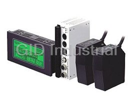
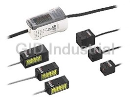
Advanced intelligent Sensors
CCD Style
Ultra High-speed Laser Displacement Sensor
HL-C1SERIES
FDA
Conforming to
FDA regulations
Conforming to
HL-C135C-BK10 and
EMC Directive
()
HL-C1□F(-BK) only
High speed of 100 μs
Ultra high-speed & stable measurement for a variety of measurement objects
Stable high-speed measurement is now available for a variety of measurement
objects, through the combination of SUNX's unique 100 μs high-speed sampling
optical system together with a linear image sensor.
Black rubber with a low reflected light intensity, objects with uneven surfaces, specular objects, such as wafers, and
transparent objects, such as the glass used in liquid crystal displays.
SUNX has now integrated all the technologies required to enable stable and consistent measurement of these
objects, which were previously considered as difficult objects to be measured.
Through the fusion of our unique newly developed optical system, linear image sensor method and high-speed
sampling technology, a wide variety of objects can now be stably measured with great precision at ultra high speeds.
Linear image sensor element
Emitting element (semiconductor laser)
Reflector
100 μs, fast sampling rate Resolution of 1 μm 0.039 mil, linearity of ±0.1 % F.S.
Ultra high-speed sampling of 100 μs has now been achieved, thus enabling Now available with ultra-precise 1 μm 0.039 mil resolution measurement
ultra high-speed measurement of rotating, vibrating and moving objects. capability (HL-C105□) and a linearity of ±0.1 % F.S. (for all models).
High precision measurement is now possible, unaffected FDA regulations conforming types are available
FDA regulations conforming types, most suitable for equipment used
by the surface condition of the detected object
in the USA, are available.
All deficiencies inherent in the conventional PSD sensing method have now
been solved. Whereas the PSD method measures position information from
the center of gravity of the total light quantity distribution of the light spots
For detection of a V-shaped groove
connected along each light element, the linear image sensor method Principle
measures the peak position values of the light spots themselves. This
As the sensor measures the peak position of the
advancement now makes high-precision measurement possible, regardless
light spot, it is not affected by secondary reflected
of the surface condition of the object whether for metal hairline surface
light, resulting in no error.
cracks or for non-reflective black rubber.
True center
Image sensor
element
Change in measurement data due to color difference
(White Ceramic / Black Rubber)
As the sensor measures the center of gravity of the
entire light quantity distribution of the beam spot as
● HL-C108B-BK ● PSD method
position information, errors occur due to the
(linear image sensor method)
presence of secondary reflected light.
True center
Error
PSD element
Center of
gravity
1
Positioning wafer Measuring glass substrate thickness
Checking IC pins Measuring the eccentricity of metal shaft Detecting the presence of a resin coating
Measuring disk brake thickness Inspecting tire form Measuring gap spacing in rubber belt material
5 types to suit your measurement objects
5 types and 9 models are available depending on the measurement object and distance. In addition, a wide measuring range is possible to
facilitate various measurement objects and installation conditions.
Wide range type Specular reflective type
350 mm 13.780 in
HL-C135C-BK10 HL-C108B
550 mm 21.654 in 150 mm 5.906 in
81.4 mm 3.205 in
HL-C108F
97.4 mm 3.835 in 65.4 mm 2.575 in
Measuring range:
±200 mm ±7.874 in
Measuring range:
350 mm ±200 mm 13.780 in ±7.874 in
81.4 mm ±16 mm 3.205 in ±0.630 in
±16 mm ±0.630 in
Diffuse reflective type
85 mm 3.346 in
HL-C108B-BK
105 mm 4.134 in 65 mm 2.559 in
HL-C108F-BK
Measuring range:
Specular reflective type
±20 mm ±0.787 in
85 mm ±20 mm 3.346 in ±0.787 in HL-C105B
46 mm 1.811 in
HL-C105F 42 mm 1.654 in
50 mm 1.969 in
Diffuse reflective type 50 mm 1.969 in
45 mm
55 mm Measuring range:
HL-C105B-BK
±4 mm
2.165 in 1.772 in
46 mm ±4 mm 1.811 in ±0.157 in
HL-C105F-BK
±0.157 in
Measuring range:
±5 mm
50 mm ±5 mm 1.969 in ±0.197 in
±0.197 in
Sensor head HL-C135C-BK10
Controller HL-C1C-M-WL
The long and wide range
Measures wide changes over long ranges
The long and wide range capabilities over 350 mm ±200 mm 13.780 in ±7.874 in allow
large changes to be measured. Even if the object position changes, there is no need to
change the sensor head settings or position.
Long range
150 1 150 50 mm m mm m 5.906 in 5.906 in 5.906 in
High speed and high precision even over long and wide ranges with an
Measurement center
350 mm
ultra-small head 13.780 in
Wide range
Center C Center enter
High-speed and high-precision performance has been achieved in an ultra-small head
±200 mm
350 3 350 50 mm m mm m 13.780 in 13.780 in 13.780 in
of W26.6 × H82 × D87 mm W1.047 × H3.228 × D3.425 in with a high-speed sampling of
±7.874 in!!
100 μs at a resolution of 10 μm 0.394 mil, and a linearity of ±0.1 % F.S.
550 5 550 50 mm m mm m 21.654 in 2 21.654 in 1.654 in
2
For diffuse reflective
objects, such as plastic,
rubber and metal objects
For specular reflective
objects, such as specular and
transparent objects
Compact console with touch panel and thin,
ultra-compact controller integrate high functionality to
provide a comfortable operating environment!
The compact design significantly reduces the installation space required for the controller and console.
The controller allows multiple sensor head connections, reducing costs and saving space, yet incorporating a great
variety of convenient functions.
The HL-C1 series integrates outstanding measurement performance and signal processing technology into a truly
comfortable operating environment.
Equipped with serial input / output
An RS-232C interface for serial input and
output is provided so that settings can be
retrieved and saved.
Measurement values can also be retrieved.
Controller
HL-C1C-M (-WL)
(Photo-MOS relay output type)
Serial Input / Output
Compact console
HL-C1DP1-E (-WL)
Connection cable, 2 m 6.562 ft long
[Accessory for the HL-C1DP1-E (-WL)]
Innovative
feature
Touch panel operation,
easy and compact
A variety of settings and measurement data
Extension cable
can be displayed easily. (Optional)
HL-C1CCJ2 (2 m 6.562 ft)
HL-C1CCJ5 (5 m 16.404 ft)
HL-C1CCJ10 (10 m 32.808 ft)
HL-C1CCJ20 (20 m 65.617 ft)
HL-C1CCJ30 (30 m 98.425 ft)
Sensor heands
HL-C135C-BK10 HL-C135C-BK10
HL-C108B-BK HL-C108F-BK
HL-C105B-BK HL-C105F-BK
HL-C108B HL-C108F
HL-C105B HL-C105F
2 sensor heads can be connected!
Reduces costs and saves space
The controller, to which 2 sensor heads can
be connected, incorporates 2 separate
input / output channels.
This feature saves the expense and space
usually required by a second controller,
whenever 2 sensor heads are used.
3
Calculations can be performed when 2 sensor heads are used Compact controller and front connection
The built-in calculation function allows measurement of gap and reduce setup space
thicknesses without requiring a digital panel controller, thus saving
The ultra-compact controller HL-C1C-M with dimensions of W40 ×
further on costs and space.
H120 × D74 mm W1.575 × H4.724 × D2.913 in requires much less
space for installation. Tight installation is also possible. Furthermore,
the cables can be connected directly or to a removable terminal block,
so that all connections come from the same direction in order to
further save space.
40 mm 1.575 in
Results of calculation
(HL-C1C-M-WL: 60 mm 2.362 in)
Removable
Judgment output
Side-by-side
terminal block
installation OK!
Results of calculation
Digital output
120 mm
4.724 in
Results of calculation
Analog output
Enhanced functionality
74 mm 2.913 in
The HL-C1 series incorporates a great number of useful functions,
including hold function, calculation function, filter function and
hysteresis-setting function, which facilitate convenient usage in a
variety of diverse applications.
Low-pass / High-pass Filter Functions Analog Output Switching Function During Alarm Output
During measurement, if the unit becomes incapable of performing
measurements due to excessive or insufficient incident light intensity (during
For example, if the surface condition of a metal object causes noise that
alarm output), this function allows the analog output to be switched to either
interferes with accurate measurement, the use of the low-pass filter function will
hold the data obtained just previously, or to output a fixed value. If the fixed
reduce the effects of noise and allow for stable measurement of displacement.
value is selected, one of two options can be chosen for the analog output,
during alarm output: the output of the maximum value (voltage output:
Measuring the eccentricity
+10.9 V, current output: 29.5 mA) or the output of the minimum value (voltage
of a metal shaft
output: -10.9 V, current output: 0 mA).
Maximum analog output value
Performing measurements on
The analog output can be used to
an object that contains a hole
confirm whether or not the unit is
capable of performing measurements.
Data hold from previous measurement
This function can be used when the effect of
When measuring seams and gaps in objects that undergo large displacement
the hole must be ignored.
changes due to vibration or tilting, such as measuring the eccentricity of a rotating
object, this function will minimize the effects of these undulations and enable
Time
accurate measurement of seams and gaps.
Detecting the seams of
a metal drum
Hold Functions
The HL-C1 series incorporates 4 hold modes.
NORM This mode outputs the amount of displacement from the measurement center
(no hold) distance in real time. This mode is utilized for general-purpose operation.
This mode holds the output at the difference between the maximum and minimum
P-P
measured values. This mode is utilized for vibration or eccentricity measurements.
PEAK This mode holds the output at the maximum measured value.
VALLEY This mode holds the output at the minimum measured value.
Waterproof sensor head construction, Easy maintenance with sensor head
compliant with IP67 rated protection compatibility
The HL-C1 series can Maintainability has been significantly improved. Compatibility has
withstand water been achieved through the incorporation of correction data into the
splashes. sensor heads themselves. This sensor series no longer needs the
amount of maintenance usually required for conventional
displacement sensors of its class.
Note: Accurate measurement cannot be performed
if water is present on the sensing window of
the sensor head itself.
4
Amount of displacement
HL-C1 HL-C1
ORDER GUIDE
Sensor heads
Conforming
Measurement Resolution Applicable Applicable
standards /
Type Appearance Beam diameter Model No.
center distance (Note 1, 2) controller console
regulations
400 × 200 μm
10 μm IEC / JIS
15.748 × 7.874 mil HL-C135C-BK10 HL-C1C-M-WL HL-C1DP1-E-WL
350 mm 13.780 in
0.394 mil / FDA
approx.
(Measuring range ±200 mm ±7.874 in)
HL-C108B-BK IEC / JIS
100 × 140 μm
2 μm
3.937 × 5.512 mil
85 mm 3.346 in
0.079 mil
FDA /
approx.
HL-C108F-BK
(Measuring range ±20 mm ±0.787 in)
IEC / JIS
HL-C105B-BK IEC / JIS
70 × 120 μm
1 μm
2.756 × 4.724 mil
50 mm 1.969 in
0.039 mil
FDA /
approx.
(Measuring range ±5 mm ±0.197 in)
HL-C105F-BK
IEC / JIS
HL-C1C-M HL-C1DP1-E
HL-C108B IEC / JIS
100 × 140 μm
2 μm
3.937 × 5.512 mil
81.4 mm 3.205 in
0.079 mil
approx.
FDA /
(Measuring range ±16 mm ±0.630 in)
HL-C108F
IEC / JIS
HL-C105B IEC / JIS
70 × 120 μm
1 μm
2.756 × 4.724 mil
46 mm 1.811 in
0.039 mil
approx.
FDA /
(Measuring range ±4 mm ±0.157 in)
HL-C105F
IEC / JIS
Notes: 1) These values were obtained by converting P-P values into a distance. The P-P values indicate the distribution of measured values throughout the
measurement center distance.
2) These values were obtained with an average number of samples: 256, when using an object made of our companys standard white ceramic for
measurement (an aluminum vapor deposition surface reß ection mirror was used with specular reß ective types).
Controllers
Type Appearance Model No. Judgment outputs
Standard
HL-C1C-M
Photo-MOS relay
For HL-C135C-BK10
HL-C1C-M-WL
Compact consoles
Type Appearance Model No.
Standard
HL-C1DP1-E
For HL-C1C-M-WL HL-C1DP1-E-WL
5
Specular reß ective type Diffuse reß ective type
High precision General purpose High precision General purpose Wide range
HL-C1
ORDER GUIDE
Sensor head extension cable
Appearance Model No. Description
Length: 2 m 6.562 ft, Net weight: 160 g approx.
HL-C1CCJ2
Length: 5 m 16.404 ft, Net weight: 350 g approx.
HL-C1CCJ5
Cabtyre cable with connector on both ends
Cable outer diameter: ø7 mm ø0.276 in
HL-C1CCJ10 Length: 10 m 32.808 ft, Net weight: 700 g approx.
Connector outer diameter: ø14.7 mm
ø0.579 in max.
HL-C1CCJ20 Length: 20 m 65.617 ft, Net weight: 1,400 g approx.
HL-C1CCJ30 Length: 30 m 98.425 ft, Net weight: 2,000 g approx.
Intelligent monitor
Appearance Model No. Description
Enables the waveform display of each measurement condition setting and of measurement values
HL-C1AiM as well as monitoring of measurement data and received light intensity data.
1pc. of COM port connection cable manufactured by Matsushita Electric Works, Ltd. is attached.
SPECIFICATIONS
Sensor heads
Diffuse reß ective type
Type
Wide range General purpose High precision
IEC / JIS standards conforming type HL-C108B-BK HL-C105B-BK
HL-C135C-BK10
Item FDA regulations conforming type HL-C108F-BK HL-C105F-BK
Measurement center distance 350 mm 13.780 in 85 mm 3.346 in 50 mm 1.969 in
Measuring range ±200 mm ±7.874 in ±20 mm ±0.787 in ±5 mm ±0.197 in
Resolution (Note 2, 3) 10 μm 0.394 mil 2 μm 0.079 mil 1 μm 0.039 mil
Linearity (Note 4) ±0.1 % F.S.
Temperature characteristics 0.02 % F.S./°C
Laser emission indicator Green LED (lights up during laser emission or immediately before laser emission)
Measuring range indicator Yellow LED (blinks within the measuring range and lights up when near the measurement center distance)
Pollution degree 3 (Industrial environment)
Protection IP67 (IEC) (excluding the connector)
Ambient temperature 0 to +45 °C +32 to +113 °F (No dew condensation), Storage: 20 to +70 °C 4 to +158 °F
Ambient humidity 35 to 85 % RH, Storage: 35 to 85 % RH
Ambient illuminance Incandescent light: 3,000 ℓx at the light-receiving face
Voltage withstandability 500 V AC for one min. between the exclusive controller power input part and the sensor head enclosure
Insulation resistance 20 MΩ, or more, with 500 V DC megger between the exclusive controller power input part and the sensor head enclosure
Vibration resistance 10 to 55 Hz (period: 1 min.) frequency, 1.5 mm 0.059 in amplitude in X,Y and Z directions for two hours each
2
Shock resistance 196 m/s acceleration (20 G approx.) in X,Y and Z directions for three times each
Red semiconductor laser, Class 3B (Class III b Red semiconductor laser, Class 2 (Class II for FDA regulations)
Emitting element for FDA regulations) (Max. output: 10 mW, (IEC / JIS standards conforming type: IEC / JIS, FDA regulations conforming type:
Peak emission wavelength: 658 nm 0.026 mil) FDA / IEC / JIS) (Max. output: 1 mW, Peak emission wavelength: 658 nm 0.026 mil)
Beam diameter (Note 5) 400 × 200 μm 15.748 × 7.874 mil approx. 100 × 140 μm 3.937 × 5.512 mil approx. 70 × 120 μm 2.756 × 4.724 mil approx.
Receiving element Linear image sensor
Enclosure earthing Floating
Material Enclosure: Die-cast aluminum, Case cover: Die-cast aluminum, Front cover: Glass
Cable Cabtyre cable, 0.5 m 1.640 ft long with connector
Cable extension Extension up to total 30 m 98.425 ft is possible, with optional cable.
Weight Net weight: 300 g approx.
Accessory English warning label: 1 set [The FDA regulations conforming type includes a set of both the IEC label (written in English) and JIS label (written in Japanese)].
Notes: 1) Where measurement conditions have not been speciÞ ed precisely, the conditions used were as follows: supply voltage 24 V DC, ambient temperature +20 °C +68 °F,
sampling rate 100 μs, average number of samples: 256 (HL-C135C-BK10: 512), object measured at measurement center distance is made of white ceramic (an aluminum
vapor deposition surface reß ection mirror was used with specular reß ective type). Linearity also depends upon the characteristics of the object being measured.
2) These values were obtained by converting P-P values into a distance. The P-P values indicate the distribution of measured values throughout the measurement center distance.
3) These values were obtained with an average number of samples: 256 (HL-C135C-BK10: 512), when using an object made of our companys standard
white ceramic for measurement (an aluminum vapor deposition surface reß ection mirror was used with specular reß ective types).
4) This value indicates the range of errors for an ideal linear displacement output, when using an object made of our companys standard white ceramic for measurement (an
aluminum vapor deposition surface reß ection mirror was used with specular reß ective types). This value may ß uctuate depending on the characteristics of the object measured.
2
5) These values were deÞ ned by using 1/e (13.5 %) of the center light intensity. If there is a slight leakage of light outside the normal spot diameter and if
the periphery surrounding the sensing point has a higher reß ectivity than the sensing point itself, then the results may be affected.
6
Environmental resistance
Model No.
HL-C1 HL-C1
SPECIFICATIONS
Sensor heads
Specular reß ective type
Type
General purpose High precision
IEC / JIS standards
HL-C108B HL-C105B
conforming type
FDA regulations
Item HL-C108F HL-C105F
conforming type
Measurement center distance 81.4 mm 3.205 in 46 mm 1.811 in
Measuring range ±16 mm ± 0.630 in ±4 mm ±0.157 in
Resolution (Note 2, 3) 2 μm 0.079 mil 1 μm 0.039 mil
Linearity (Note 4) ±0.1 % F.S.
Temperature characteristics 0.02 % F.S./°C
Laser emission indicator Green LED (lights up during laser emission or immediately before laser emission)
Measuring range indicator Yellow LED (blinks within the measuring range and lights up when near the measurement center distance)
Pollution degree 3 (Industrial environment)
Protection IP67 (IEC) (excluding the connector)
Ambient temperature 0 to +45 °C +32 to +113 °F (No dew condensation), Storage: 20 to +70 °C 4 to +158 °F
Ambient humidity 35 to 85 % RH, Storage: 35 to 85 % RH
Ambient illuminance Incandescent light: 3,000 ℓx at the light-receiving face
Voltage withstandability 500 V AC for one min. between the exclusive controller power input part and the sensor head enclosure
Insulation resistance 20 MΩ, or more, with 500 V DC megger between the exclusive controller power input part and the sensor head enclosure
Vibration resistance 10 to 55 Hz (period: 1 min.) frequency, 1.5 mm 0.059 in amplitude in X,Y and Z directions for two hours each
2
Shock resistance 196 m/s acceleration (20 G approx.) in X,Y and Z directions for three times each
Red semiconductor laser, Class 2 (Class II for FDA regulations) (IEC / JIS standards conforming type: IEC / JIS,
Emitting element
FDA regulations conforming type: FDA / IEC / JIS) (Max. output: 1 mW, Peak emission wavelength: 658 nm 0.026 mil)
Beam diameter (Note 5) 100 × 140 μm 3.937 × 5.512 mil approx. 70 × 120 μm 2.756 × 4.724 mil approx.
Receiving element Linear image sensor
Enclosure earthing Floating
Material Enclosure: Die-cast aluminum, Case cover: Die-cast aluminum, Front cover: Glass
Cable Cabtyre cable, 0.5 m 1.640 ft long with connector
Cable extension Extension up to total 30 m 98.425 ft is possible, with optional cable.
Weight Net weight: 300 g approx.
Accessory English warning label: 1 set [The FDA regulations conforming type includes a set of both the IEC label (written in English) and JIS label (written in Japanese)].
Notes: 1) Where measurement conditions have not been speciÞ ed precisely, the conditions used were as follows: supply voltage 24 V DC, ambient temperature
+20 °C +68 °F, sampling rate 100 μs, average number of samples: 256, object measured at measurement center distance is made of white ceramic
(an aluminum vapor deposition surface reß ection mirror was used with specular reß ective type). Linearity also depends upon the characteristics of the
object being measured.
2) These values were obtained by converting P-P values into a distance. The P-P values indicate the distribution of measured values throughout the
measurement center distance.
3) These values were obtained with an average number of samples: 256, when using an object made of our companys standard white ceramic for
measurement (an aluminum vapor deposition surface reß ection mirror was used with specular reß ective types).
4) This value indicates the range of errors for an ideal linear displacement output, when using an object made of our companys standard white ceramic for
measurement (an aluminum vapor deposition surface reß ection mirror was used with specular reß ective types). This value may ß uctuate depending on
the characteristics of the object measured.
2
5) These values were deÞ ned by using 1/e (13.5 %) of the center light intensity. If there is a slight leakage of light outside the normal spot diameter and if
the periphery surrounding the sensing point has a higher reß ectivity than the sensing point itself, then the results may be affected.
7
Environmental resistance
Model No.
HL-C1
SPECIFICATIONS
Controllers
Photo-MOS relay output
Type
Standard For HL-C135C-BK10
Item Model No. HL-C1C-M HL-C1C-M-WL
Connection sensor heads Maximum 2 sensor heads
Supply voltage 24 V DC ±10 % including ripple 0.5 V (P-P)
Current consumption When 1 sensor is connected: 430 mA approx., When 2 sensors are connected: 550 mA approx.
Sampling rate Selectable from 100 μs / 144 μs / 200 μs / 255 μs / 332 μs / 498 μs / 1,000 μs
Temperature characteristics ±0.01 % F.S./°C
Output voltage: ±5 V/F.S. [default setting when diffuse reß ective mode is selected (Note 2)]
Voltage Output range: 10.9 to +10.9 V
Output current: Max. 2 mA, Output impedance: 50 Ω
Output current: 4 to 20 mA/F.S. [default setting when diffuse reß ective mode is selected (Note 4)]
Current (Note 3) Output range: 0 to 29.5 mA (maximum of 25 mA at max. load impedance)
Load impedance: 250 Ω or less
Photo-MOS relay
Maximum load current: 50 mA
Alarm output Applied voltage: 30 V DC or less (between alarm output and COM)
ON impedance: 35 Ω or less
Operation time: Max. 2 ms
Output operation Opened when the amount of light is excessive or insufÞ cient.
Short-circuit protection Incorporated
Photo-MOS relay
Maximum load current: 50 mA
Judgment outputs
Applied voltage: 30 V DC or less (between judgment output and COM)
(O1, O2)
ON impedance: 35 Ω or less
Operation time: Max. 2 ms
Utilization category DC-12 or DC-13
Opened or closed when the threshold value is reached. Determined based on judgment output mode selection. (The threshold value varies with the hysteresis setting.)
Output operation
Short-circuit protection Incorporated
Serial input / output RS-232C
Laser emission stops or continues when voltage (using input
Timing input voltage: 12 to 24 V DC, maximum input voltage: 30 V DC) is
(Laser emission) input or there is an open circuit: determined based on input
mode selection.
Remote interlock input Laser emission stops when open circuit
Zero set ON input Zero set: ON when voltage (using input voltage: 12 to 24 V DC, maximum input voltage: 30 V DC) is input
Zero set OFF input Zero set: OFF when voltage (using input voltage: 12 to 24 V DC, maximum input voltage: 30 V DC) is input
Laser emission Green LED (lights up during laser emission from sensor head 1 or sensor head 2, or immediately before laser emission)
BRIGHT Red LED (lights up upon disabled measurement due to excessive light at sensor head 1 or 2)
DARK Red LED (lights up upon disabled measurement due to insufÞ cient light at sensor head 1 or 2)
Setting / Data display Compact console (optional)
Shift ±20.0000 mm ±0.787 in ±200.0000 mm ±7.874 in
Span 0.9000 to 1.1000
Average number of samples (Note 5) OFF, 2 to 32,768 times (16 steps)
Digital Þ lters (Note 5) High pass: OFF, 10 to 2,000 Hz (9 steps), Low pass: OFF, 10 to 2,000 Hz (9 steps)
L ± KA, L ± KB, L ± K (A ± B)
Calculation functions (Note 5)
A, B: Sensor head 1, Sensor head 2 measurement values, L = ±999.9999, K = 0.0001 to 99.9999
Hold functions (Note 5) Selectable from NORMAL / P-P / PEAK / VALLEY
Pollution degree 3 (Industrial environment)
Ambient temperature 0 to +50 °C +32 to +122 °F (No dew condensation), Storage: 20 to +70 °C 4 to +158 °F
Ambient humidity 35 to 85 % RH, Storage: 35 to 85 % RH
Voltage withstandability 500 V AC for one min. between power input part and enclosure
Insulation resistance 20 MΩ, or more, with 500 V DC megger between power input part and enclosure
Vibration resistance 10 to 55 Hz frequency (period: 1 min.) 0.75 mm 0.030 in amplitude in X,Y and Z directions for 30 min. each
2
Shock resistance 196 m/s (20 G approx.) in X, Y and Z directions for 3 times each
Cable length Power line: Less than 10 m 32.808 ft, Signal line: Less than 30 m 98.425 ft
Net weight: 300 g approx.
Weight
Accessory Key: 2 pcs.
Notes: 1) Where measurement conditions have not been speciÞ ed precisely, the conditions used were as follows: supply voltage 24 V DC, ambient temperature
+20 °C + 68 °F, sampling rate 100 μs, average number of samples: 256 (HL-C1C-M-WL: 512), and measurement center distance.
2) If specular reß ective mode is selected, then the default setting is ±4 V/F.S.
3) The maximum analog output current will vary with load impedance.
4) If specular reß ective mode is selected, then the default setting is 5.6 to 18.4 mA/F.S.
5) These values can be set using the command input from external equipment via the compact console and RS-232C interface.
8
Calibration
Environmental resistance Indicators Analog output
(Note 5)
HL-C1 HL-C1
SPECIFICATIONS
Compact consoles
Type Standard For HL-C1C-M-WL
Item Model No. HL-C1DP1-E HL-C1DP1-E-WL
Supply voltage 24 V DC ±10 % including ripple 0.5 V (P-P)
Current consumption 200 mA or less
Display element STN monochrome LCD
Back light White LED
Display range 999.9999 to 999.9999
Language English
Operation force 0.5 N or less
Lifetime 1,000,000 times or more (Note 1)
IP65 (at initial status) (Note 2)
Environment resistance
Dust prevention and drip-proof at the front panel (waterproof packing is used at the contact surface to board)
Ambient temperature 0 to +50 °C +32 to +122 °F (No dew condensation or icing allowed), Storage: 20 to +60 °C 4 to +140 °F
Ambient humidity 20 to 85 % RH, Storage: 10 to 85 % RH
Electrostatic noise resistance 5,000 V or more (panel surface)
Vibration resistance 10 to 55 Hz frequency, 0.75 mm 0.030 in amplitude in X, Y, and Z directions for 10 min. each
2
Shock resistance 98 m/s or more acceleration (10G approx.) in X, Y, and Z directions for four times each
Material Case: PPE, Front protective sheet: Polyester
Weight 230 g approx.
Accessory Connection cable for connecting the controller to the console: 1 pc., Mounting bracket: 1 set
Notes: 1) This value indicates the average lifetime of the unit when used under a normal temperature of +25 °C +77 °F.
2) When reinstalling the console, replace the water proof packing. (Matsushita Electric Works, Ltd., Part No: AIGT181, 10 packs included)
9
Touch
Environmental resistance Display
panel
HL-C1
I/O CIRCUIT AND WIRING DIAGRAMS
Controller
HL-C1C-M(-WL)
Input circuit diagram Output circuit diagram
Connection example 1 (NPN)
Alarm output, Judgment output
+V
Output Input Connection example 1 (NPN)
Output
5 V DC Load
0 V
+
30 V DC
50 mA max.
COM
max.
–
Photoelectric HL-C1C-M(-WL)
(–)
sensor, etc.
COM
HL-C1C-M(-WL)
Connection example 2 (PNP)
+V Connection example 2 (PNP)
Output
5 V DC +
30 V DC
Output Input
max.
50 mA max.
–
Load
COM
HL-C1C-M(-WL)
COM
Photoelectric (–) HL-C1C-M(-WL)
sensor, etc.
Analog output diagram
–10.9 to +10.9 V
Voltage
50 Ω
output
GND GND
+12 V DC
0 to 29.5 mA
Current
output
GND GND
HL-C1C-M(-WL)
Analog input device
Notes: 1) Do not short-circuit analog output terminals or apply vottage to them.
2) Use shielded wires for analog outputs.
Terminal arrangement
Input terminals Output terminals
Symbol Description Symbol Description
TM1 TM1 (Note 1) Timing input (sensor head 1) (Note 1) AL1 AL1 Alarm output (sensor head 1)
I11 O11
I11 Zero set ON input (sensor head 1) Judgment output 1 (sensor head 1)
O11
I12 O12
( )
I12 Zero set OFF input sensor head 1 O12 Judgment output 2 (sensor head 1)
COM COM
COM Input common COM Output common
TM2 AL2
TM2 (Note 2) Timing input (sensor head 2) (Note 2) Alarm output (sensor head 2)
I21 O21 AL2
I22 ( ) O22
I21 Zero set ON input sensor head 2 O21 Judgment output 1 (sensor head 2)
COM COM
I22 Zero set OFF input (sensor head 2) O22 Judgment output 2 (sensor head 2)
• •
COM Input common Output common
COM
• •
Not used Not used
• V1
• Not used I1 Not used
• GND
Not used Analog voltage output (sensor head 1)
V1
+ V2
Not used I1 Analog current output (sensor head 1)
– I2
Not used Analog output ground
GND
GND
+ 24 V DC input for power supply Analog voltage output (sensor head 2)
V2
Power supply ground I2 Analog current output (sensor head 2)
Function ground Analog output ground
GND
Notes: 1) In the case of HL-C1C-M-WL, IL1: Remote interlock input (sensor head 1)
2) In the case of HL-C1C-M-WL, IL2: Remote interlock input (sensor head 2)
3) Terminals marked with are not used. Some are connected to internal circuitry and cannot be used as relay terminals in wiring, etc.
SENSING CHARACTERISTICS (TYPICAL)
Diffuse reß ective type
HL-C135C-BK10
Correlation between measuring distance and error characteristics Vertical positioning Horizontal positioning
0.4 0.4
White ceramic (0°, ±30°) White ceramic (0°, ±30°)
+30° +30°
Sampling rate: 100 μs Sampling rate: 100 μs
Vertical orientation Horizontal orientation
0° Average number 0° Average number
– + Sensor
+ –
–30° of samples: 512 –30° of samples: 512
0.2 0.2
Sensor
0 0
L
L
Measuring
Measuring
object object
–0.2 –0.2
–0.4 –0.4
150 250 350 450 550 150 250 350 450 550
5.906 9.843 13.780 17.717 21.654 5.906 9.843 13.780 17.717 21.654
(Center) (Center)
Measuring distance L (mm in) Measuring distance L (mm in)
10
Main circuit Main circuit
Error (%F.S.)
Error (%F.S.)
HL-C1 HL-C1
SENSING CHARACTERISTICS (TYPICAL)
HL-C108□-BK Diffuse reß ective type
Correlation between measuring distance and error characteristics Vertical positioning Horizontal positioning
0.4
0.4
+10° Sampling rate: 100 μs +10° Sampling rate: 100 μs
White ceramic (0°, ±10°) White ceramic (0°, ±10°)
Average number Average number
0° 0°
Vertical orientation Horizontal orientation
of samples: 256 of samples: 256
–10° –10°
– + + – Sensor head
0.2 0.2
Sensor head
0 0
L
L
Measuring
Measuring
object
object
–0.2 –0.2
–0.4 –0.4
65 75 85 95 105 65 75 85 95 105
2.559 2.953 3.346 3.740 4.134 2.559 2.953 3.346 3.740 4.134
(Center) (Center)
Measuring distance L (mm in) Measuring distance L (mm in)
HL-C105□-BK Diffuse reß ective type
Correlation between measuring distance and error characteristics Vertical positioning Horizontal positioning
0.4 0.4
White ceramic (0°, ±10°) White ceramic (0°, ±10°)
+10°
+10° Sampling rate: 100 μs
Sampling rate: 100 μs
Vertical orientation Horizontal orientation
0° 0°
Average number Average number
–
+ + –
Sensor head –10° of samples: 256 –10° of samples: 256
0.2 0.2
Sensor head
0 0
L
L
Measuring
Measuring
object
object
–0.2 –0.2
–0.4 –0.4
45 47.5 50 52.5 55 45 47.5 50 52.5 55
1.772 1.870 1.969 2.067 2.165 1.772 1.870 1.969 2.067 2.165
(Center) (Center)
Measuring distance L (mm in) Measuring distance L (mm in)
HL-C108B HL-C108F Specular reß ective type
Correlation between measuring distance and error characteristics Vertical positioning Horizontal positioning
0.4 0.4
Aluminum vapor deposition Aluminum vapor deposition
+0.2° +0.1°
Sampling rate: 100 μs Sampling rate: 100 μs
surface reflection mirror surface reflection mirror
0° Average number 0° Average number
–0.2° –0.1°
(0°, ±0.2°) (0°, ±0.1°) of samples: 256 of samples: 256
0.2 0.2
Vertical orientation Horizontal orientation
– –
+ +
Sensor head
Sensor head
0 0
L
L
–0.2 –0.2
Measuring
Measuring
object
object
–0.4 –0.4
65.4 73.4 81.4 89.4 97.4 65.4 73.4 81.4 89.4 97.4
2.575 2.890 3.205 3.520 3.835 2.575 2.890 3.205 3.520 3.835
(Center) (Center)
Measuring distance L (mm in) Measuring distance L (mm in)
Specular reß ective type
HL-C105B HL-C105F
Correlation between measuring distance and error characteristics Vertical positioning Horizontal positioning
0.4 0.4
Aluminum vapor deposition Aluminum vapor deposition
+0.5° +0.2°
Sampling rate: 100 μs Sampling rate: 100 μs
surface reflection mirror surface reflection mirror
0° 0°
Average number Average number
(0°, ±0.5°) (0°, ±0.2°) –0.5° of samples: 256 –0.2° of samples: 256
0.2 0.2
Vertical orientation Horizontal orientation
–
– + +
Sensor head
Sensor head
0 0
–0.2 –0.2
L
L
Measuring
Measuring
object
object
–0.4 –0.4
42 44 46 48 50 42 44 46 48 50
1.654 1.732 1.811 1.890 1.969 1.654 1.732 1.811 1.890 1.969
(Center)
(Center)
Measuring distance L (mm in) Measuring distance L (mm in)
11
Error (%F.S.) Error (%F.S.) Error (%F.S.) Error (%F.S.)
Error (%F.S.) Error (%F.S.) Error (%F.S.) Error (%F.S.)
HL-C1
PRECAUTIONS FOR PROPER USE
Sensor head mounting direction
This catalog is a guide to select a suitable product. Be
To obtain the greatest precision, the sensor head should
sure to read instruction manual attached to the product
be oriented facing the direction of movement of the
prior to its use.
objects surface, as shown in the Þ gure below.
Never use this product as a sensing device
Rotating object
for personnel protection.
In case of using sensing devices for
personnel protection, use products which
meet laws and standards, such as OSHA,
ANSI or IEC etc., for personnel protection
applicable in each region or country.
HL-C108□
This product is classiÞ ed as a Class 2 Laser
HL-C105□
Product in IEC / JIS standards and a Class
II Laser Product in FDA regulations. Do not
look at the laser beam directly or through
optical system such as a lens.
Object that has large differences in gaps, grooves and colors
The following label is attached to the product.
Handle the product according to the instruction
given on the warning label.
The English warning label based on
FDA regulations is pasted on the
FDA regulations conforming type.
(The English warning label is packed with the sensor)
This product is classiÞ ed as a Class 3B
HL-C135C-BK10
Laser Product in IEC / JIS standards Class
IIIb. Never look at or touch the direct laser
Safety standards for laser beam products
beam and its reß ection.
The following label is attached to the
A laser beam can harm human beings eyes, skin, etc.,
product. Handle the product according to the
because of its high energy density. IEC and JIS have
instruction given on the warning label.
classiÞ ed laser products according to the degree of
hazard and the stipulated safety requirements.
The English warning label based on HL-C108□ and HL-C105□: ClassiÞ ed as Class 2 laser products
FDA regulations is pasted on the
HL-C135C-BK10: ClassiÞ ed as a Class 3B laser products
FDA regulations conforming type.
ClassiÞ cation by IEC 60825-1: 2001
(The English warning label is packed with the sensor)
ClassiÞ cation Description
To comply with the European EMC Directive (HL-C1C-M-WL)
To comply with the European EMC Directive, install a
Lasers that are safe under reasonably foreseeable conditions of
Class 1
ferrite core on wires to the terminal block as shown below.
operation, including the use of optical instruments for intrabeam viewing.
Recommended ferrite core: Lasers emitting in the wavelength range from 302.5 nm to 4,000 nm
Class 1M which are safe under reasonably foreseeable conditions of operation,
E04RC281613 manufactured by Seiwa Electric Mfg. Co., Ltd or
but may be hazardous if the user employs optics within the beam.
equivalent
Lasers that emit visible radiation in the wavelength range from
400 nm to 700 nm where eye protection is normally afforded
COM
by aversion responses, including the blink reß ex.
Class 2
This reaction may be expected to provide adequate protection
COM
under reasonably foreseeable conditions of operation
including the use of optical instruments for intrabeam viewing.
Lasers that emit visible radiation in the wavelength range
from 400 nm to 700 nm where eye protection is normally
COM
Class 2M afforded by aversion responses, including the blink reß ex.
However, viewing of the output may be more hazardous if
COM
the user employs optics within the beam.
6
Lasers that emit in the wavelength range from 302.5 nm to 10 nm
where direct intrabeam viewing is potentially hazardous but the risk is
Class 3R
lower than for Class 3B lasers, and fewer manufacturing requirements
Ferrite Core
and control measures for the user apply than for Class 3B lasers.
Lasers that are normally hazardous when direct intrabeam exposure
Class 3B
occurs (i.e. within the NOHD). Viewing diffuse reß ections is normally safe.
Lasers that are also capable of producing hazardous diffuse reflections.
Class 4
They may cause skin injuries and could also constitute a fire hazard.
12
HL-C1 HL-C1
PRECAUTIONS FOR PROPER USE
Safe use of laser products Mutual interference
For the purpose of preventing users from suffering When installing 2 or more sensor heads side by side,
injuries by laser products, IEC 60825-1: 2001 (JIS C mutual interference will not occur if the laser spots from
6802: 2005) (Safety of laser products). other sensor heads do not fall within the shaded areas
Kindly check the standards before use. of the sensor head in the Þ gure below. Multiple sensor
heads must be installed in a manner such that laser spots
from other sensor heads will be prevented from falling
Summary of user precautions IEC 60825-1: 2001 (JIS C 6802: 2005)
within these shaded areas. When two sensor heads
* Quoted from Safety of laser products, Annex Table D. 3
are connected to a controller and used, the measures
described below are not required since the mutual
ClassiÞ cation
Requirements
interference prevention function can be used.
subclause
Class 1 Class 1M Class 2 Class 2M Class 3R Class 3B Class 4
HL-C108□ HL-C105□
Not required
for visible
Laser Not required but recommended for
emission
safety applications that involve direct Required
Required for
ofÞ cer viewing of the laser beam
non-visible
emission
Remote Connect to room
Not required
interlock or door circuits
18
44.5
8
0.709 55.5
4 0.157
3
64 1.752 0.315
Remove key 2.185
Key control Not required 0.118
2.520
when not in use
11 0.433
106
2 2
4.173
4 10 0.079 0.079
Beam When in use prevents
Not required
42 0.157 0.394
attenuator inadvertent exposure
1.654
(Unit: mm in)
indicates
2 2
4 26
laser is
0.079 0.079
Emission 0.157 1.024
energized Indicates laser
(Unit: mm in)
indicator Not required
for is energized
device
HL-C135C-BK10
non-visible
wavelengths
Warning Follow precautions
Not required
signs on warning signs
Class 1M Class 2M
Not Not Terminate beam at end
Beam path (Note 1) as for (Note 2) as for
required required of useful length
Class 3B Class 3B
36 1.417
145
10 0.394
Class 1M Class 2M
5.709
Specular No No Prevent unintentional
(Note 1) as for (Note 2) as for
reß ection requirements requirements reß ections
Class 3B Class 3B
Required if
555
engineering and 21.850
410
Eye administrative
No requirements
16.142
protection procedures not
practicable and
MPE exceeded
Protective Sometimes SpeciÞ c
6 6
No requirements 27 124
clothing required requirements
0.236 0.236
1.063 4.882
(Unit: mm in)
Class 1M Class 2M Required for all operator
No No
Functional description
Training (Note 1) as for (Note 2) as for and maintenance
requirements requirements
Class 3R Class 3R personnel
Sensor head
Notes: 1) Class 1M laser products that failed condition 1 of table 10.
Not required for Class 1M laser products that failed condition 2 of
1
table 10.
2
2) Class 2M laser products that failed condition 1 of table 10.
Not required for Class 2M laser products that failed condition 2 of
table 10.
Remarks: This table is intended to provide a convenient summary of
precautions. See text of this standard for complete precautions.
3
Description Function
Laser emission
Lights up during laser emission or immediately
1 indicator
before laser emission.
(Green LED)
Measuring range
Blinks within the measuring range and lights up
2 indicator
when near the measurement center distance.
(Yellow LED)
3
Warning label Shows the laser emission position.
13
HL-C1
PRECAUTIONS FOR PROPER USE
Functional description
Details
Function
Controller
The measurement value and analog output at the timing of zero
Zero set setting are forcibly reset to zero. Use this function to reset the
AL1 LASER 1 1
function measurement value of the reference object to zero and measure the
O11 BRIGHT
O12
DARK
displacement amount or make a judgment of the upper or lower limit.
COM NOT USE COM
AL2
2 2
O21
The judgment outputs (O1 and O2) immediately before
O22
COM
COM
3 3
the mode selection, measurement value and analog
COM.
11
11 Timing function
V1 output are held in the timing input mode. Laser emission
I 1 4 4
excluding
GND
can be halted or continued according to a setting. Add the
V2
HL-C1C-M-WL
I 2
input in other than the measurement or judgment state to
GND 5 5
TM1
eliminate unnecessary output changes or laser radiation.
I 11
I 12 NOT USE
6 6
COM
COM
12 12 This function stops laser radiation. Turning on the remote
TM2
I 21 Remote interlock
7 7
I 22 HEAD 1 interlock input maintains the judgment output and then either
COM COM
function
holds values measurement values or analog outputs to the
8 8 [HL-C1C-M-WL only]
14
values just obtained or outputs the Þ xed values.
HEAD 2
9 10 9
Only the measurement value displayed on the compact
10
Display hold
console is held. Use this function to read a momentary
13 13
function
measurement value.
In cases where objects with a low reß ected light amount, such as
black rubber, are measured, stable measurements can be taken
Description Function by extending the sampling rate and enabling a sufÞ cient amount
Switching
of light to be picked up by the sensor. If the sampling rate is short
functions for
and not enough light can be picked up, the sensor enters the alarm
sampling rate
Laser emission Lights up during laser emission from sensor head 1
state, so switch the sampling rate to a longer duration setting. The
1 indicator or sensor head 2, or immediately before laser
sampling rate can be switched among 7 different rates.
(Green LED) emission.
(100 μs / 144 μs / 200 μs / 255 μs / 332 μs / 498 μs / 1,000 μs)
This function enables the unit to perform the following calculations:
BRIGHT
Lights up upon disabled measurement due to
2 indicator
excessive light at sensor head 1 or 2.
L1 + K1A: normal output state
(Red LED)
L2 + K2B: normal output state
L1 K1A: reverses the polarity of the measured value
DARK indicator Lights up upon disabled measurement due to
3
L2 K2B: reverses the polarity of the measured value
(Red LED) insufÞ cient light at sensor head 1 or 2.
Calculation
Cannot be used. This port is for adjustment at the L + K (A + B): addition
4
function
factory before shipping. L K (A + B): used when measuring thickness
L + K (A B): subtraction, used when measuring level differences
Used for RS-232C communications with a personal
L K (A B): used when reversing the polarity of a subtraction output
5
COM. port
computer.
A: the value measured by sensor head 1
B: the value measured by sensor head 2
Connector for This enables measurement values to be displayed using the
L: the amount of offset for the measured value
6 compact compact console and connection of the compact console
K: the coefÞ cient used to adjust the ratio of displacement changes
console exclusive connection cable when setting each setting.
The measurement mode (diffuse reß ective / specular
reß ective) can be switched between these two modes, in
Cannot be used. This port is for adjustment at the
7
accordance with the sensor head selected, based on the
factory before shipping.
measurement object.
Sensor head 1 The controller operates the sensor head connected Diffuse reß ective mode: used when measuring a substance without
8
connector to this connector as sensor head 1. a mirror surface or not transparent.
Specular reß ective mode: used when measuring a substance with
Sensor head 2 The controller operates the sensor head connected
a mirror surface or is transparent.
9
connector to this connector as sensor head 2.
When in specular reß ective mode, the measurement
object can be selected from the following options:
Power supply Supplies 24 V DC. There are power supply
Standard: used when measuring the mirror surface of
10
terminal terminals on input terminal block.
opaque substance such as metal, etc.
Front: used when measuring the surface of transparent
11
External output terminal
substance such as glass, etc.
Switching
Rear: used when measuring the rear surface of transparent
functions for
12 External input terminal
substance such as glass, etc.
measurement
DIN rail Can be mounted on a 35 mm 1.378 in width DIN The measurement center distance is shifted.
mode
13
mounting hook rail quickly.
Thickness: used when measuring the thickness of
transparent substance such as glass.
Turning on the key switch starts up the controller.
14 Key switch
The refraction angle is
Please take out the key when it is not being used.
compensated to 1.55. Standard
There is a limitation in
Opaque
measurable thickness.
substance
Surface
Functions
Rear surface
Thickness measurement
reflection
reflection
guidelines for common glass sheets:
General-purpose model
Function Details
thicknesses 1.2 mm 0.047 in or more
Transparent
Thickness
High precision model
substance
It is possible to accumulate data up to 48,000 data into
thicknesses 0.5 mm 0.020 in or more
a controller temporarily in order to capture measurement
For example, if the surface conditions of a metal object
Data buffering data into a PC. All the accumulated data can be captured
cause noise that interferes with accurate measurement,
function into the PC with HL-C1AiM. Used for reading and storing
the use of the low-pass Þ lter function will reduce the
all data including the veriÞ cation of measurement data
effects of noise and allow for the stable measurement of
when introduced as well as all post-measurement data.
displacement. 9 independent cutoff frequencies can be
NORM. (no hold): Outputs the amount of displacement
Low-pass Þ lter
selected, OFF or ranging from 10 to 2,000 Hz.
from the measurement center distance in real time.
function
Ordinarily, this mode is used.
P-P: This mode holds and outputs the difference
Hold function
between the maximum value and the minimum value. It
is used for vibration measurements or eccentricity.
PEAK: Holds and outputs the maximum measurement value.
VALLEY: Holds and outputs the minimum measurement value.
14
HL-C1
PRECAUTIONS FOR PROPER USE
Functions
Function Details Function Details
If joints or grooves are being measured in the midst
Hysteresis Optional hysteresis settings can be selected for both
of great changes such as runout or inclination in an
setting function the upper and lower limits.
eccentric rotating object etc., this setting minimizes the
effects of gradual changes and makes it possible to This function causes the output to correspond to the
detect joints or grooves. 9 independent cutoff frequencies measurement value wanted at an analog output of
High-pass Þ lter
can be selected, OFF or ranging from 10 to 2,000 Hz. +5 V (20 mA) and at 5 V (4 mA). It can be used for
function
scaling of the analog output or for making the output
Analog output greater or smaller, etc.
setting function When this function is used, the analog output
corresponding to measurement values ranging
between, for example, 70 to 90 mm 2.756 to 3.543 in,
can be assigned to outputs ranging from 5 V
(for 70 mm 2.756 in) to +5 V (for 90 mm 3.543 in).
If the measured values are subject to rapid
ß uctuation, then increasing the average number of
You can switch between the data having been output
Switching function samples will allow the unit to compensate for these
immediately before and a Þ xed value as an analog
for average number ß uctuations, enabling stable measurements to be
output issued when measurement is disabled (with
of samples obtained. The average number of samples can be
Analog output an alarm output) due to an excessive or insufÞ cient
selected from among 16 steps, ranging from OFF to
switching amount of light or deviation from the range. When the
32,768 times.
function during Þ xed value setting is selected, either the maximum
alarm value (voltage output: +10.9 V, current output: 29.5
The judgment output O1, O2 (NC) can be selected from
mA) or minimum value (voltage output: 10.9 V,
the four types listed in the table below.
current output: 0 mA) of the analog output is issued
Logical output and judgment
during an alarm.
Judgment IN
LOW HIGH
Output RANGE
Display
The timing signal at the input terminal functions as an
O1 1 0 1
Input selection input upon a short circuit by default setting.
Upper limit value (HIGH)
Lower limit value (LOW) function Use this function to activate the input upon an open
O2 0 1 1
Displacement
circuit.
IN
LOW HIGH
(+) 1: Output state
RANGE
Measurement errors may occur due to the color,
Select to distinguish the side of
Open
O1 LOW
the measurement value around material or surface condition of the object being
Close
Open
the lower limit value setting. The
measured. These differences can be compensated
O2 LOW
Close
upper limit setting is ignored.
for through calibration.
Calibration
The calibration function allows the span and shift to
Select to distinguish between
Open function
O1 LOW be set for each sensor head. There are two ways to
Close
the upper limit and lower limit
Judgment
Open
set these values. One is to conduct auto setting by
when the measurement value
output selection O2 HIGH
Close
exceeds either limit. moving a piece of the object past sensors and the
function
other is to input previously measured values directly.
Select to distinguish between
Open
deviation from the upper or lower
O1 LOW or HIGH
This function displays the peak level of light received
Close
Open limit value and containment in
Display light at the measuring point.
O2 IN RANGE
Close
the range. Use this for OK / NG
received The usage of this function when installing sensor
judgment.
function heads allows the optimum marginal increment to be
Select to distinguish whether
used as the level of light received for measurement.
the measurement value is below
Open
the lower limit value, above the
This function saves all setting data except for the
O1
Close
Save function
LOGIC upper limit value or within the
Open
timing input state and display hold state.
O2
Close range. Build an external logical
circuit to judge two outputs and
separate them into three states.
: Output state (excluding hysteresis area)
* The output state is the state in which the terminal is open. (NC)
15
10.5°
21°
ø7 ø0.276 cable
ø7 ø0.276 cable
ø14.7 ø0.579
ø14.7 ø0.579
ø7 ø0.276 cable
ø7 ø0.276 cable
ø14.7 ø0.579
ø14.7 ø0.579
ø14.7 ø0.579
ø7 ø0.276 cable
DIMENSIONS (Unit: mm in)
The CAD data in the dimensions can be downloaded from the SUNX website: http://www.sunx.com
Sensor head Sensor head
HL-C108□-BK HL-C108B HL-C108F
2-M5 mounting 2-M5 mounting
holes, 10 holes, 10
Specular reflection sensor head
3.3 0.130
26.6
0.394 deep 0.394 deep setting reference surface
26.6
1.047
4.15 0.163
(for both sides) (for both sides)
12.9 81.4 98.8
1.047 87
3.3
3.890 4.15 0.163
12.9 0.508 Measuring range indicator 0.508 3.205
3.425
0.130 11 0.433
Beam 5 88.8
Measuring range indicator
(Yellow)
(Note 2)
3.496
attenuator (Note) 0.197
(Yellow)
0.3 Beam receiving axis
Laser emission indicator
39.7
Beam receiving axis Laser emission indicator
82 0.012
72 0.3
(Green)
1.563
3.228 83.4 (Green)
2.835 0.012
56.8
83.7
21° 3.283
36.2 ( )
31.2 (Note 2)
3.295 2.236
(Note 2)
1.425
1.228
5 0.197 31.4
Beam
530 26.5
emitting 1.236
1.043
20.866
16.9 85 77 axis
0.665 3.346 3.031 530
5 0.197 Measurement center
Measurement Beam attenuator
20.866
center (Note 1)
Beam
emitting axis
Note: There is not beam attenuator on IEC / JIS standards conforming type.
Notes: 1) There is not beam attenuator on IEC / JIS standards conforming type.
2) Figure shows standard installation level dimensions.
HL-C105□-BK Sensor head HL-C105B HL-C105F Sensor head
2-M5 mounting 2-M5 mounting
holes, 10 holes, 10
Specular reflection sensor head
26.6 Beam receiving axis
3.3 0.130
0.394 deep 0.394 deep setting reference surface
26.6
1.047
4.15 0.163 101.2
12.9 46
87 (for both sides) (for both sides)
1.047
3.3 3.984
Measuring range indicator 0.508 1.811 4.15 0.163
12.9 0.508 3.425
12.4 0.488
0.130 91.2
5
Measuring range indicator
(Yellow)
(Note 2)
Beam attenuator (Note)
0.197 3.951
(Yellow)
0.3 Laser emission indicator
Beam receiving axis
41.3
0.012 (Green)
82
72 0.3 Laser emission indicator
1.626
83.4
3.228
2.835 0.012 52.8
83.7
(Green)
36.2 3.283
31.2 ( )
2.079
3.295 (Note 2)
(Note 2)
1.425
1.228
16.9 0.665
5 0.197
30.1
25.3
530
1.185
0.996
20.866
77
Measurement 50
Beam emitting axis
3.031 530
center 1.969 5
Beam attenuator
20.866
0.197 Measurement center
Beam
(Note 1)
emitting axis
Note: There is not beam attenuator on IEC / JIS standards conforming type.
Notes: 1) There is not beam attenuator on IEC / JIS standards conforming type.
2) Figure shows standard installation level dimensions.
HL-C135C-BK10 Sensor head HL-C1C-M Controller
(4.7 0.185) 3.3 0.130 4-M3,
87
(1.5 0.059) (1.4 0.055) 1.5 0.059 deep
4.15 0.163
26.6
3.425
55
2-M5 mounting holes, 10 40
1.047 5.5 (8.1 0.319)
13.3 ( ) 2.165
0.394 deep (for both sides) 1.575
0.217
Measuring range indicator
0.524
Beam
(Yellow)
receiving axis
0.3
Laser emission indicator
Beam
0.012
82
attenuator
(Green)
72 2.835
3.228
6° 104
120
(3.6 0.142)
4.094
36.2
31.2 4.724
(1.5 0.059)
1.228 1.425
530
20.866
16.9
5 0.197
350
77
0.665
13.780
3.031
5
10
Measurement 74
( )
0.197
center 0.394
2.913
Beam
emitting axis
16
13°
26°
26°
DIMENSIONS (Unit: mm in)
The CAD data in the dimensions can be downloaded from the SUNX website: http://www.sunx.com
Controller Compact console
HL-C1C-M-WL HL-C1DP1-E(-WL)
4-M3, 26
1.024
1.5 0.059 deep
144 5.670
4 0.158
60 5.5 55 (8.1 0.319) 100 3.937 (Display part)
2 0.079
( )
2.362 2.165
0.217
(Packing)
66
40.5 72
2.598
1.595 2.835
104
120
4.094
4.724
Panel cut-out
(8 0.315)
dimensions
10
2.7
3 0.118 74
( ) +1
13.2
0.394
15 67
0.106 0
( ) 2.913
5.5 ( )
0.520
+0.039
0.591
2.638
0
0.217
72
9.5 0.374 2.835
+1
139
0
+0.039
5.472
0
136 5.354
(2 0.079) (Panel thickness: 5 mm 0.197 in)
138 5.433
Extention cable
HL-C1CCJ□
ø14.7
ø14
ø7
ø0.579
ø0.551
ø0.276
43
43
( ) ( )
1.693
1.693
Length L
Model No. Length L (mm in)
2,000 78.740
HL-C1CCJ2
HL-C1CCJ5 5,000 196.850
HL-C1CCJ10 10,000 393.700
HL-C1CCJ20 20,000 787.400
30,000 1181.100
HL-C1CCJ30
All information is subject to change without prior notice.
SUNX Limited
2431-1 Ushiyama-cho, Kasugai-shi, Aichi,
486-0901, Japan
Phone: +81-568-33-7211
FAX: +81-568-33-2631
Overseas Sales Division
Phone: +81-568-33-7861
http://www.sunx.com
FAX: +81-568-33-8591
Printed on recycled paper PRINTED IN JAPAN
No. CE-HLC1-1-5 August, 2008
L


 Manufacturers


What they say about us
FANTASTIC RESOURCE
One of our top priorities is maintaining our business with precision, and we are constantly looking for affiliates that can help us achieve our goal. With the aid of GID Industrial, our obsolete product management has never been more efficient. They have been a great resource to our company, and have quickly become a go-to supplier on our list!
Bucher Emhart Glass
EXCELLENT SERVICE
With our strict fundamentals and high expectations, we were surprised when we came across GID Industrial and their competitive pricing. When we approached them with our issue, they were incredibly confident in being able to provide us with a seamless solution at the best price for us. GID Industrial quickly understood our needs and provided us with excellent service, as well as fully tested product to ensure what we received would be the right fit for our company.
Fuji
HARD TO FIND A BETTER PROVIDER
Our company provides services to aid in the manufacture of technological products, such as semiconductors and flat panel displays, and often searching for distributors of obsolete product we require can waste time and money. Finding GID Industrial proved to be a great asset to our company, with cost effective solutions and superior knowledge on all of their materials, it’d be hard to find a better provider of obsolete or hard to find products.
Applied Materials
CONSISTENTLY DELIVERS QUALITY SOLUTIONS
Over the years, the equipment used in our company becomes discontinued, but they’re still of great use to us and our customers. Once these products are no longer available through the manufacturer, finding a reliable, quick supplier is a necessity, and luckily for us, GID Industrial has provided the most trustworthy, quality solutions to our obsolete component needs.
Nidec Vamco
TERRIFIC RESOURCE
This company has been a terrific help to us (I work for Trican Well Service) in sourcing the Micron Ram Memory we needed for our Siemens computers. Great service! And great pricing! I know when the product is shipping and when it will arrive, all the way through the ordering process.
Trican Well Service
GO TO SOURCE
When I can't find an obsolete part, I first call GID and they'll come up with my parts every time. Great customer service and follow up as well. Scott emails me from time to time to touch base and see if we're having trouble finding something.....which is often with our 25 yr old equipment.
ConAgra Foods