

 Manufacturers
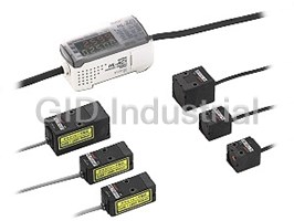
PANASONIC HL-AC1P
Description
Panasonic HL-AC1P Sensor - DIGITAL CONTROLLER FOR HL-T1,PNP,12-24VDC,3-OUT,4-20MA(+/-4V)
Part Number
HL-AC1P
Price
Request Quote
Manufacturer
PANASONIC
Lead Time
Request Quote
Category
PRODUCTS - H
Specifications
Ambient Humidity
35 to 85 % RH, Storage: 35 to 85 % RH
Ambient Temperature
0 to +50 °C +32 to +122 °F (No dew condensation), Storage: -25 to +65 °C -13 to +149 °F
Applicable sensor head
HL-T1001A/T1001F, HL-T1005A/T1005F, HL-T1010A/T1010F
EMC
EN 61000-6-2, EN 61000-6-4
I/O cable
0.09 mm2 10-core composite cable, 2 m 6.562 ft long
I/O cable extension
Extension up to total 10 m 32.808 ft is possible, with 0.09 mm2 or more, cable. (Note 6)
Insulation resistance
20 MO, or more, with 500 V DC megger between all supply terminals connected together and enclosure
Judgment outputs (HIGH, PASS, LOW)
PNP open-collector transistor Maximum source current: 50 mA Applied voltage: 30 V DC or less (between judgment output and +V) Residual voltage: 2 V or less (at 50 mA source current)
Linear Output
Current / voltage output switchable (Note 2) During current output: 4 to 20 mA/F.S., Maximum load resistance: 300 O During voltage output: ±4 V/F.S., Output impedance 100 O (In the monitor focus function, it can also be set at ±5 V, 0 to 5 V, etc.)
Material
Enclosure: Polybutylene terephthalate, Transparent cover: Polycarbonate
Measuring cycle
150 µs
Pollution Degree
3 (industrial environment)
Settable average sampling rate (Note 4)
1 / 2 / 4 / 8 / 16 / 32 / 64 / 128 / 256 / 512 / 1,024 / 2,048 / 4,096
Shock Resistance
300 m/s2 acceleration (30 G approx.) in X, Y and Z directions for three times each
Supply voltage / Current consumption
12 to 24 V DC ± 10 % Ripple P-P 10 % or less / 190 mA or less (when connected to the sensor head)
Temperature characteristics
±0.2 % F.S./°C (Note 3)
Vibration Resistance
10 to 150 Hz frequency, 0.7 mm 0.028 in amplitude in X, Y and Z directions for 80 min.
Voltage withstandability
1,000 V AC for one min. between all supply terminals connected together and enclosure
Weight
Net weight: 140 g approx.
Features
- 2-level teaching
- Adoption of a Class 1 laser
- Automatic teaching
- High-precision judgment even from
- Long sensing range
- minute differences in light intensity
- Positioning teaching
- The industry’s smallest sensor head
Datasheet

Extracted Text
ULTRA-COMPACT LASER COLLIMATED BEAM SENSOR Class 1 HL-T1SERIES Conforming to EMC Directive Achieving the Ultimate The industry’s smallest sensor head A high-functionality intelligent controller Advanced technology delivered in a compact body. The HL-T1 series of laser collimated beam sensors embody the ultimate evolution of performance, functionality and operability. These new sensors, having the highest performance and capabilities never before available, were created to meet strict demands for miniaturization arising from production sites requiring the ultimate in space-savings: HL-T1005A with a sensing width of 5mm 0.197in, HL-T1010A with a sensing width of 10mm 0.394in and HL-T1001A with a beam diameter of "1mm "0.039in. This performance enables high-precision detection, multi-functional capabilities that can adapt to the many different conditions experienced at production sites, as well as a high degree of operability to facilitate ease of use. The HL-T1 series, the new standard in laser collimated beam sensors, enhances production innovations at every work site. Min. sensing object: "0.008mm "0.00031in (Sensing range at 0 to 500mm 19.685in) Beam diameter: "1mm "0.039in (Sensing range at 0 to 500mm 19.685in) Sensing range: 2m 6.562ft HL-T1001A ("1mm "0.039in type) The ideal parallel light system has been successfully created using both a laser beam, with its superior directivity, and our unique optical technology. These features allow for ultra high-precision detection. The industry’s smallest sensor head Long sensing range Resolution of 4!m The most compact size and yet the highest Long sensing range of 500mm 19.685in A high resolution of 4!m (at level of performance in their class. These (HL-T1005A, HL-T1010A) and 2m 6.562ft an average 64 cycles) allows sensors save space. (HL-T1001A) are available. high-precision positioning and size judgment. HL-T1001A Adoption of a Class 1 laser 34mm 1.339in HL-T1005A The adoption of a Class 1 laser (IEC/JIS) 15mm 0.591in eliminates the need for safety countermeasures, Distinguishing size HL-T1010A so that these sensors can be used in photo- of electronic components 15mm 0.591in electric sensor applications with confidence. 19mm 15mm 20mm 0.748in 0.591in 0.787in Minimum sensing object diameter "8!m/HL-T1001A High-precision judgment even from The laser with a beam diameter of "1mm 15mm minute differences in light intensity "0.039in can sense extremely small 0.591in 42mm 1.654in The sensors are sensitive to minute differences in light objects with dimensions in micrometers intensity, so that they can judge even the opacity of such as bonding wires. 20mm 0.787in glass and turbidity of liquids. In addition, the amount of 20mm 0.787in 25mm 0.984in light received can be displayed as a percentage to allow you to determine permeation rates. HL-AC1 (P) 20mm 0.787in Distinguishing 64.3mm 2.531in opacity of glass 34.3mm 1.35in 30mm 1.181in 1 HL-T1010A (10mm 0.394in type) Min. sensing object: "0.1mm "0.004in Sensing width: 10mm 0.394in Sensing range: 500mm 19.685in HL-T1005A (5mm 0.197in type) Min. sensing object: "0.05mm "0.002in Sensing width: 5mm 0.197in Sensing range: 500mm 19.685in A side view attachment is available, permitting space-saving installation (optional) Mounting the side view attachment (optional) allows for a greater variety of different installation options, enabling additional space to be saved. FDA standards conforming types are available FDA standards conforming types, most suitable for equipment used in the USA, are now available. FDA : Class 2 IEC/JIS: Class 1 Mounted on both sides Mounted on one side only Checking the positioning of chip components Detecting defective lead frame seating Sensing wafer position in wafer cassette 2 ‘Using advanced functionality with ease’ The HL-T1 series has achieved this high performance goal. Large, easy-to-view dual digital displays and easy-to-use four-way keys are incorporated into the unit’s compact body. Features an intelligent controller that allows for easy utilization of its high performance features and advanced functionality. The fully equipped the HL-T1 series can adapt to every application with its convenient features – 3 types of teaching functions and a calculation function for use with two sensors. HL-AC1 (NPN output type) HL-AC1P (PNP output type) Superior operability has been achieved 3 types of teaching functions are now available All settings can be easily performed by using the four-way keys and 3 types of teaching functions are available: positioning teaching/ viewing the digital displays. 2-level teaching/automatic teaching, thus enabling a variety of applications to be accommodated for many different types of production sites. Large dual digital display After power up, the measured value (red) and the threshold value (yellow) The actual value measured at the time when teaching are displayed (digit height 7mm 0.276in) Positioning is performed is utilized as the threshold value. teaching Judgment output indicators Best suited for high-precision positioning. HIGH/PASS/LOW 3-color display In this teaching method, an intermediate level between the first and the second teaching levels is utilized as the threshold value. 2-level Minute differences, such as changes as small as the thickness teaching of a sheet of paper between the sensing objects, can be detected when this teaching method is utilized. With this teaching method, a series of periodic arbitrarily measurements are taken automatically and an intermediate value, between the maximum and minimum values obtained by this measurement, is utilized Automatic as the threshold value. The threshold value is therefore set in relation to teaching Easy operation with four-way keys the sensing object. Best suited for applications in which teaching must be performed without stopping the current flow of operations. 3 Intelligent controller; Facilitating a variety of different applications Calculations for 2 sensors are possible Self-check for laser diode The calculation unit (optional) just needs to be connected between the two controllers to deterioration enable calculations (addition and subtraction) to be carried out for two sensors. No digital The intelligent controller performs self- panel controller is needed either. checking for laser diode deterioration. If the controller detects significant deterioration (end of diode life), an error will be displayed Sheet width measurement on the main digital display panel. This function enables users to prepare in advance for potential laser diode malfunctions. Calculation unit Error display Analog output is switchable between current/voltage Detection resolution can be The analog output can be switched between either of two different outputs; current (4 to easily confirmed 20mA)/voltage (�4V). With the monitor focus function, the output can be adjusted over the The current resolution can be easily range from �5V to �5V, or from 0V to �5V, facilitating connectivity with a variety of confirmed by setting the controller to output devices. indicate resolution display mode. By displaying the resolution, the marginal Monitor focus function increment can be easily determined for the The linear output is fully adjustable over the following range (current: 4 to 20mA/voltage threshold value setting, helping to �4V). The usage of the monitor focus function together with selectable current/voltage accurately determine whether sensing can switching for the linear output allows for compatibility with a variety of output devices. be performed. Examples �5 Resolution indicator �4 In the event that �1 5mm 0.197in: �5 V 0mm 0in: �1 V 0 5.0 0.197 Sensor display value (mm) (in) In the event that �4 5mm 0.197in: �1 V 0mm 0in: �5 V �5 Fully equipped with convenient 0 5.0 0.197 functionality Sensor display value (mm) (in) A wide range of convenient features has �1 been incorporated into the unit’s compact body: standard received light setting/auto 0 5.0 scaling setting/measurement processing 0.197 (various timer and hold functions)/diffe- Sensor display value (mm) (in) rentiation/monitor focus function. These features make the unit useful for a wide The linear output must be set by determining output values (maximum: current 0 to 23.5mA/ voltage �5.5V) at two different points, for the arbitrary display value. variety of applications. 4 Linear output voltage (V) Linear output voltage (V) Linear output voltage (V) HL-T1 SPECIFICATIONS Sensor heads Type Beam diameter "1mm "0.039in type Sensing width 5mm 0.197in type Sensing width 10mm 0.394in type IEC/JIS standards conforming type HL-T1001A HL-T1005A HL-T1010A Model No. Item FDA standards conforming type HL-T1005F HL-T1010F HL-T1001F Applicable controller HL-AC1, HL-AC1P Sensing range 0 to 500mm 19.685in 500 to 2,000mm 19.685 to 78.74in 500mm 19.685in Sensing width "1mm "0.039in "1 to "2.5mm "0.039 to "0.098in 5mm 0.197in 10mm "0.394in "8!m "0.315mil "50!m "1.969mil "0.05mm "0.002in opaque object "0.1mm "0.004in opaque object Min. sensing object opaque object opaque object Repeatability 4!m 0.157mil 4!m 0.157mil (Note 1) (During the state in which light is half blocked) (Note 1) Linear output resolution 4!m 0.157mil 4!m 0.157mil (Note 1) (Note 2) (Notes 1, 3) Emission indicator Green LED (lights up during laser emission) Interference prevention function Two units of sensors can be mounted closely. (When the controller interference prevention function is used) Polution degree 3 (industrial environment) Ambient temperature 0 to�50˚C �32 to �122˚F (No dew condensation), Storage:�25 to�70˚C �13 to�158˚F Ambient humidity 35 to 85% RH, Storage: 35 to 85% RH Ambient illuminance Incandescent light: 10,000?x at the light-receiving face EMC Emission: EN50081-2, Immunity: EN50082-2 Voltage withstandability 1,000V AC for one min. between all supply terminals connected together and enclosure Insulation resistance 100MΩ, or more, with 250V DC megger between all supply terminals connected together and enclosure Vibration resistance 10 to 500Hz frequency, 1.5mm 0.059in amplitude in X, Y and Z directions for two hours each 2 Shock resistance 300mm/s acceleration (30G approx.) in X, Y and Z directions for three times each Red semiconductor laser Class 1 (IEC / JIS) Red semiconductor laser Class 1 (IEC / JIS) IEC/JIS standards modulated, max. output: 0.2mW modulated, max. output: 0.35mW conforming type ( ) ( ) peak emission wavelength: 650nm peak emission wavelength: 650nm Red semiconductor laser Class 2 (FDA) Red semiconductor laser Class 2 (FDA) FDA standards modulated, max. output: 0.2mW modulated, max. output: 0.35mW ( ) ( ) conforming type peak emission wavelength: 650nm peak emission wavelength: 650nm (IEC / JIS: Class 1) (IEC / JIS: Class 1) Material Enclosure: Polyestherimide, Case cover: Polycarbonate, Front cover: Glass 2 2 Cable 0.09mm 0.004in 3-core shielded cable with connector, 0.5m 1.64ft long Cable extension Extension up to total 10m 32.808ft is possible, with the optional cable. (Note 4) Weight Emitter: 15g 0.529oz approx., Receiver: 15g 0.529oz approx. Emitter: 30g 1.058oz approx., Receiver: 20g 0.705oz approx. MS-HLT1-1 (Sensor head mounting bracket): One set of two brackets for MS-LA3-1 (Sensor head mounting bracket): both the emitter and the receiver One set of two brackets for both the emitter and the receiver Accessories CN-HLT1-1 (Sensor head to controller connection cable): 1 No. CN-HLT1-1 (Sensor head to controller connection cable): 1 No. Laser beam alignment sticker: 2 Nos. Laser beam alignment sticker: 2 Nos. Label set (FDA standards conforming type only): 1 set Label set (FDA standards conforming type only): 1 set Notes: 1) In case of an average sampling rate of 64 times. 2) Value calculated with the linear output allowance factor (�3�) when connected to the controller included in the calculation of the detection width. 3) This value was obtained by converting the range of linear output fluctuation (�3�) into a sensing width, assuming that the smallest sensing object blocks the beam at the approximate center of the beam diameter of "1mm "0.039in. 4) The following types of extension cables are available (for extending the distance between the sensor head-controller connection cable and the controller itself) HL-T1CCJ4 (4m 13.123ft) HL-T1CCJ8 (8m 26.247ft) Calculation unit Model No. HL-AC1-CL Item Connected controller HL-AC1, HL-AC1P Current consumption 12mA or less (supplied from the controller) Connection method Connector Connection indicator Orange LED (lights up when connected to the controller) Ambient temperature 0 to�50˚C �32 to�122˚F (No dew condensation), Storage:�15 to�60˚C �5 to�140˚F Ambient humidity 35 to 85% RH, Storage: 35 to 85% RH Voltage withstandablity 1,000V AC for one min. between all supply terminals connected together and enclosure Insulation resistance 100MΩ, or more, with 500V DC megger between all supply terminals connected together and enclosure Vibration resistance 10 to 150 Hz frequency, 0.7mm 0.028in amplitude in X, Y and Z directions for 80minutes 2 Shock resistance 300m/s acceleration (30G approx.) in X, Y and Z directions for three times each Material Enclosure: ABS, Indicator part: Acrylic Weight 50g 1.764oz approx. 5 Emitting element Environmental resistance Environmental resistance HL-T1 SPECIFICATIONS Controllers Type NPN output PNP output Item Model No. HL-AC1 HL-AC1P Applicable sensor head HL-T1001A/F, HL-T1005A/F, HL-T1010A/F Supply voltage / Current consumption 12 to 24V DC�10% Ripple P-P 10% or less / 190mA or less (when connected to the sensor head) Measuring cycle 150!s Current / voltage output switchable (Note 1) • During current output: 4 to 20mA/F.S., Maximum load resistance: 300Ω Linear output • During voltage output:�4V/F.S., Output impedance 100Ω (In the monitor focus function, it can also be set at�5V, 0 to 5V, etc.) Temperature characteristics �0.2% F.S./˚C (Note 2) Settable average sampling rate (Note 3) 1 / 2 / 4 / 8 / 16 / 32 / 64 / 128 / 256 / 512 / 1,024 / 2,048 / 4,096 NPN open-collector transistor PNP open-collector transistor Judgment output • Maximum sink current: 50mA • Maximum source current: 50mA (HIGH, PASS, LOW) • Applied voltage: 30V DC or less (between judgment output and 0V) • Applied voltage: 30V DC or less (between judgment output and�V) • Residual voltage: 1.2V or less (at 50mA sink current) • Residual voltage: 2V or less (at 50mA source current) Utilization category DC-12 or DC-13 Number of outputs HIGH / PASS / LOW 3 values output HIGH: ON when measured value � HIGH threshold value Output operation PASS: ON when HIGH threshold value j measured value j LOW threshold value LOW: ON when LOW threshold value � measured value Short circuit protection Incorporated 0V connection: Laser emission stop �V connection: Laser emission stop Laser OFF input Open: Laser emission Open: Laser emission • Applied voltage: 30V DC or less (at 0.1mA leak current) • Applied voltage: 30V DC or less (at 0.1mA leak current) 0V connection: Zero reset operates �V connection: Zero reset operates Zero reset input Open: Zero reset ineffective Open: Zero reset ineffective • Applied voltage: 30V DC or less (at 0.1mA leak current) • Applied voltage: 30V DC or less (at 0.1mA leak current) 0V connection: Effective �V connection: Effective Timing input Open: Ineffective Open: Ineffective • Applied voltage: 30V DC or less (at 0.1mA leak current) • Applied voltage: 30V DC or less (at 0.1mA leak current) 0V connection: Effective �V connection: Effective Reset input Open: Ineffective Open: Ineffective • Applied voltage: 30V DC or less (at 0.1mA leak current) • Applied voltage: 30V DC or less (at 0.1mA leak current) Laser emitting (LD ON) Green LED (lights up during laser emisson) HIGH: Orange LED (lights up when measured value � HIGH threshold value) PASS: Green LED (lights up when HIGH threshold value j measured value j LOW threshold value) Judgment output LOW: Yellow LED (lights up when LOW threshold value � measured value) Enable (ENABLE) Green LED (lights up during normal operation) Zero reset (ZERO) Green LED (lights up when the zero reset function is enabled) RUN mode: Either the measured value (mm) or the hold value will be displayed. Main digital display 5 digit red LED display Reverse mode: The display orientation will be reversed. RUN mode: Either the resolution or laser beam reception amount will be displayed. Sub-digital display 5 digit yellow LED display THR mode: The threshold value will be displayed., Reverse mode: The display orientation will be reversed. • Measured value • Display reverse • Zero reset • Positioning teaching • (A�B) calculation display • ECO display • Initial reset • 2-level teaching (Note 4) • Setting value, light • Display digits limitation • ON-delay timer • Automatic teaching • Mutual interference amount value • Sample hold • OFF-delay timer • Hysteresis width variablily prevention (Note 4) resolution display • Peak hold • ONE SHOT timer • Monitor focus • Laser deterioration Main functions • Standard received light • Bottom hold • Differentiation • Non-measuring time detecton setting • Peak to peak hold • Sensitivity selection setting • Key lock • Automatic scaling • Self peak hold • Threshold value direct • (A�B) calculation • Zero reset memory • Scaling • Self bottom hold setting (Note 4) Pollution degree 3 (industrial environment) Ambient temperature 0 to�50˚C �32 to�122˚F (No dew condensation), Storage:�25 to�65˚C �13 to�149˚F Ambient humidity 35 to 85% RH, Storage: 35 to 85% RH EMC Emission: EN50081-2, Immunity: EN50082-2 Voltage withstandability 1,000V AC for one min. between all supply terminals connected together and enclosure Insulation resistance 20MΩ, or more, with 500V DC megger between all supply terminals connected together and enclosure Vibration resistance 10 to150Hz frequency, 0.7mm 0.028in amplitude in X, Y and Z directions for 80 minutes 2 Shock resistance 300m/s acceleration (30G approx.) in X, Y and Z directions for three times each Enclosure: Polybutylene terephthalate, Transparent cover: Polycarbonate Material 2 2 I/O cable 0.09mm 0.004in 10-core composite cable, 2m 6.562ft long 2 I/O cable extension Extension up to total 10m 32.808ft is possible, with 0.09mm or more, cable. (Note 5) 140g 4.938oz approx. Weight Notes: 1) Switching between current and voltage is accomplished by a switch on the bottom of the controller. 2) These are the temperature characteristics of the linear output when the sensor head is connected. 3) The judgment output and linear output and linear output response time is calculated by (Measuring cycle)�(Set average sampling rate�1). 4) The calculation unit is necessary. 5) If the extension cable is longer than 10m 32.808ft, then it will not qualify for CE marking. 6 Environmental resistance Indicators HL-T1 I/O CIRCUIT DIAGRAMS HL-AC1 NPN output type HL-AC1P PNP output type Color code Color code (Brown) �V (Brown) �V D1 D1 (White) HIGH Tr1 Load 50mA max. judgment output Tr1 Load (White) HIGH judgment output 50mA max. Tr2 ZD1 Load ZD1 Load 50mA max. (Green) PASS judgment output � � Tr2 12 to 24V DC 12 to 24V DC �10% �10% (Green) PASS judgment output � � 50mA max. Tr3 ZD2 ZD2 Load 50mA max. (Gray) LOW judgment output Tr3 (Gray) LOW judgment output 50mA max. Load (Blue) GND (0V) (Blue) GND (0V) ZD3 ZD3 m1 m1 (Pink) LD-OFF input (Pink) LD-OFF input m1 m1 (Violet) Timing input (Violet) Timing input m1 m1 (Orange/Violet) Zero reset input (Orange/Violet) Zero reset input m1 m1 (Red) Reset input (Red) Reset input Current output Current output 4 to 20mA 4 to 20mA (Black) Linear output (Black) Linear output Current output: Current output: 300Ω or less 300Ω or less Voltage Voltage Load Load 100Ω 100Ω Voltage output: Voltage output: (Shield) Linear GND (Shield) Linear GND output �4V output �4V 10kΩ or more 10kΩ or more Internal circuit Users’ circuit Internal circuit Users’ circuit Symbols ... D: Reverse supply polarity protection diode Symbols ... D: Reverse supply polarity protection diode ZD1, ZD2, ZD3: Surge absorption zener diode ZD1, ZD2, ZD3: Surge absorption zener diode Tr1, Tr2, Tr3: NPN output transistor Tr1, Tr2, Tr3: PNP output transistor m1 m1 Non-voltage contact or Non-voltage contact or NPN open-collector transistor PNP open-collector transistor or or Low (0 to 1.5V): Effective Low (0V or open): Ineffective High (�V or open): Ineffective High [�V to (�V�1.5V)]: Effective SENSING CHARACTERISTICS (TYPICAL) HL-T1001A HL-T1005A HL-T1001F HL-T1005F Correlation between transverse Correlation between transverse Correlation between interrupted deviation and output voltage deviation and output voltage beam width and output voltage 8 8 8 250mm The left graph depicts the Sensing object Horizontal direction Vertical direction Horizontal direction Vertical direction 2m 2m 500mm 500mm Emitter ? � Receiver Receiver Receiver correlation between Receiver Receiver Emitter Emitter Emitter Emitter 6 ? ? 6 ? ? 6 transverse deviation and � output voltage when the 500mm The graph depicts the full-scale setting ranges correlation between 4 4 4 Vertical direction Vertical direction transverse deviation and from 0V (light beam is output voltage when the full- Horizontal direction scale setting ranges from 0V Horizontal direction interrupted) to 5V (light (light beam is interrupted) to 5V (light beam is fully 2 2 2 beam is fully incident), incident), using the Monitor Focus function. using the monitor focus function. 0 0 0 4 2 0 2 4 10 5 05 10 �10 �5 05 10 0.157 0.079 0.079 0.157 0.394 0.197 0.197 0.394 �0.394 �0.197 0.197 0.394 (Up)Left Center Right (Down) (Up)Left Center Right (Down) Screeing edge position ? (mm) (in) Deviation ? (mm) (in) Deviation ? (mm) (in) HL-T1010A HL-T1010F Correlation between transverse Correlation between interrupted deviation and output voltage beam width and output voltage 8 8 250mm Sensing object Horizontal direction Vertical direction 500mm 500mm Emitter ? Receiver � Receiver Receiver Emitter Emitter 6 6 ? ? � The graph depicts the 500mm Vertical direction correlation between transverse deviation and 4 4 Horizontal direction output voltage when the full- scale setting ranges from 0V (light beam is interrupted) to 5V (light beam is fully incident), using the Monitor 2 2 Focus function. 0 0 10 5 05 10 –10 –5 05 10 0.394 0.197 0.197 0.394 �0.394 �0.197 0.197 0.394 (Up)Left Center Right (Down) Screeing edge position ? (mm) (in) Deviation ? (mm) (in) 7 Linear output voltage (V) Linear output voltage (V) Sensor circuit Linear output voltage (V) Linear output voltage (V) Sensor circuit Linear output voltage (V) HL-T1 PRECAUTIONS FOR PROPER USE Functional description • Never use this product as a sensing device for personnel protection. 16 5 3B 9A • In case of using sensing devices for personnel protection, use 2 products which meet standards, such as OSHA, ANSI or IEC etc., for personnel applicable in each region or country. This product is equivalent to a IEC/JIS Standard Class 1 Laser device. Do not expose your eyes to the laser beam through optical instruments, like a lens. • For more detailed product information, please refer to the 4 8 7 0 C instruction manual accompanying this product. Safety measures for laser beam products Description Function • The safety standard IEC Publication 60825 specifies the use of laser beam products. Laser emitting Lights up when the sensor head is emitting laser indicator (LD ON) Please read it carefully before using the laser beam sensor. 1 beam. (Green LED) Functions at a glance Judgment output indicators HIGH: Orange LED (lights up when measured value � HIGH threshold value) (HIGH / PASS / LOW) PASS: Green LED (lights up when HIGH threshold value j measured value 2 (Orange / Green / j LOW threshold value) Function Details Yellow LED) LOW: Yellow LED (lights up when LOW threshold value � measured value) Main digital When in the RUN mode, it displays the measured value (mm/%). The following tasks can be done by executing zero reset. display During measurement hold, it displays the hold value (mm/%). 3 • The display value can be set at “0”. (5 digit red LED) In Reverse mode, the top and bottom are displayed in reverse. Zero reset • The linear output when the display reads “0” is made the center function When in the RUN mode, it displays the threshold value, voltage / output value of the 2 points set by monitor focus. (In the default Sub-digital current value, light reception amount or resolution. When in the state, the current output is 12mA and the voltage output is 0V.) display (5 digit 4 THR mode, it displays the respective threshold values. In yellow LED) The auto scaling function selects whether to display the laser beam reverse mode, the top and bottom are displayed in reverse. reception amount in the main-digital display in mm units or in % units, Enable indicator Lights up when operation is normal. Goes off when and determines whether the amount of laser beam received or the Auto scaling (ENABLE) operation is abnormal (if the sensor head is not 5 amount of laser beam interrupted is displayed. With the set standard function (Green LED) connected when the power is turned on). laser beam reception amount as the reference value, the current laser beam reception amount (laser beam interrupted amount) is scaled Zero reset automatically and is displayed as well as being output. indicator (ZERO) Lights up when the zero reset function is enabled. 6 (Green LED) This function registers and stores the current laser beam reception The following 3 modes can be selected. amount in memory as the standard laser beam reception amount. Mode select • RUN mode: Measuring mode The laser beam reception amount during full laser beam entry Standard 7 switch • THR mode: The threshold values are set in this mode. becomes the 100% laser beam reception amount’s full scale (F.S.). received light • FUN mode: Each of the settings are set in this mode. If this function is used, the display and the linear output are set on setting the full scale (F.S.) automatically. It can also be used to correct the Threshold value When in the THR / RUN mode, this switches the set 8 laser beam reception amount when there is a change in the laser select switch threshold value (HIGH / LOW). beam reception amount due to dirt, etc. on the front glass. • RUN mode: Timing input Up key The scaling function is a function that changes the display value 9 • THR mode: Changes the threshold value (forward direction) Scaling function to the desired amount with respect to the setting value. At the • FUN mode: Changes the function setting value (forward direction) desired distance, the display value can be input and changed. • RUN mode: Press for 3 sec. or more: Standard light reception Hysteresis width setting DOWN key This function sets the hysteresis to the desired value. amount setting input 0 • THR mode: Changes the threshold value (reverse direction) With this function, the linear output range and inclination, etc. with respect Monitor focus • FUN mode: Changes the function setting value (reverse direction) to the display value can be specified. Setting is done by determining the 2 function output values with respect to the desired display values. • RUN mode: Changes the contents of the sub-digital display RIGHT key (forward direction) This function makes the amount of change in the measured A • THR mode: Changes the threshold value digit (forward direction) value an output value. Use this function when measuring if Differential • FUN mode: Sets function selection (forward direction) you are paying attention to changes in measured values, function • RUN mode: Changes the contents of the sub-digital display as when counting the number of work pieces, etc. LEFT key (reverse direction) The digital display’s display direction can be selected. The B • THR mode: Changes the threshold value digit (reverse direction) Display reverse forward direction or the reverse direction to match the • FUN mode: Sets function selection (reverse direction) function direction of installation on the equipment can be selected. • RUN mode: Pressing for 1 sec. or more, executes zero reset. ECO display function This function makes the display dark and saves electric power. Pressing together with the RIGHT key for 3 sec. or more, cancels zero reset. This determines the number of display digits in the main-digital Display digits • THR mode: When threshold value is blinking, the threshold value and sub-digital displays. If the number of digits is limited, the ENT key limitation function is set. When the threshold value lights up, teaching is C digits are turned off beginning with the lowest order digit. executed. This selects whether or not to save the zero reset level in memory • FUN mode: When the set value is blinking, the value is set. Zero reset when the power is turned OFF. If you desire to reproduce the zero When the setting is being initialized, pressing for a memory reset level from the previous operating session when you turn the long time executes initialization. function power ON again, then enable this function. If this function is enabled, the zero reset level data are written into the EEPROM each time. Others The controller’s key input can be disabled. Once the key input is Key lock • This product outputs the judgment of the laser light analog quantity. Since there is disabled, the controller will not accept any key inputs until the key lock function variation in the light intensity between the center and the edges of the detection area, is released. Use this function to avoid changing the setting by mistake. and emitter side and the receiver side, the ‘display value’ does not equal ‘the actual dimensions’, so caution is necessary. Use the displayed dimensional value as a criterion. Connection • If the object being measured has a mirror surface or is a transparent body, • This product is made to satisfy the specifications when the sensor head is it may be impossible to measure it accurately, so please exercise caution. combined with the controller. In any other combination, not only may it not satisfy the specifications, but could be the cause of breakdown. So by all • Absolutely do not attempt to disassemble this product. means, use it so that there is a combination of the sensor head and controller. 8 HL-T1 DIMENSIONS (Unit: mm in) HL-T1001A (F) Sensor head HL-T1005A (F) 2-"3.2 "0.126 34 19 2.8 0.2 0.008 1.339 0.748 "2.6 "0.102 cable 0.5m 1.64ft (Gray) 0.11 2.8 0.11 16 (1.5) (0.059) 5 0.197 "2.6 "0.102 cable 0.5m 1.64ft (Black) 0.63 9 0.354 15 0.591 9 0.354 15 Manufactured (6.9) (0.272) 2-"3.2 "0.126 Manufactured 0.591 by Molex (36.5) by Molex 51029-0410 (1.437) 51029-0410 Certification/identification label (Note 1) (50!m polyester film) (10) (0.394) Light beam shielding plate (Note 1) Emission indicator (Green) Beam axis (Note 2) 15 15 0.591 0.591 Emitter Receiver Notes: 1) IEC/JIS conforming products do not contain light beam shielding plate, or certification/identification label. 2) The receiver of HL-T1001A (F) does not incorporate a slit. HL-T1010A Sensor head HL-T1010F 2-"3.2 "0.126 42 25 0.2 2.8 2.8 0.11 "2.6 "0.102 cable 1.654 0.984 0.008 0.11 0.5m 1.64ft (Gray) "2.6 "0.102 cable 0.5m 1.64ft (Black) 10 0.394 (6.9) (0.272) 14 20 20 14 0.551 0.787 0.787 0.551 Manufactured Manufactured by Molex by Molex 22 (36.5) (1.5) (0.059) 51029-0410 2-"3.2 "0.126 51029-0410 0.866 (1.437) Certification/identification label (Note) (50!m polyester film) (10) (0.394) Light beam shielding plate (Note) Emission indicator Beam axis (Green) 20 20 0.787 0.787 Emitter Receiver Note: IEC/JIS conforming products do not contain light beam shielding plate, or certification/identification label. HL-AC1 Controller HL-AC1-CL Calculation unit (Optional) HL-AC1P Mounting drawing with a mounting bracket MS-HLAC1-1 Calculation unit connector Linking connector (Optional) (on each side) 24.9 0.98 32.2 1.268 (3.6) (0.142) 64.3 2.531 30 1.181 Connection indicator (Orange) 34.3 4.3 1.35 0.169 15.8 13.2 15.1 0.622 0.52 0.594 57 2.244 12 0.472 54.9 2.161 8 0.315 22.4 16 "5.2 "0.205 cable 3.9 0.882 0.63 2m 6.562ft 0.154 13 0.512 36.8 Suitable for 35mm 1.378in 30 26 1.449 1.181 2-"3.2 "0.126 width DIN rail 1.024 5.4 150 5.906 approx. 0.213 5 36.7 1.445 3.4 32.2 3.4 0.197 3.4 0.134 0.134 "5.1 "0.201 cable 1.268 0.134 16.1 0.634 Sensor head 5.4 0.213 connector 22.4 16 0.882 0.63 9 HL-T1 DIMENSIONS (Unit: mm in) Sensor head mounting bracket for HL-T1001A (F)/HL-T1005A (F) MS-HLT1-1 [This accessory is included with the HL-T1001A (F)/HL-T1005A (F). Also available for purchase separately.] Assembly dimensions 3.4 0.134 12 7 5 Mounting drawing with HL-T1005A’s receiver 1.1 9 0.276 0.197 "3.2 "0.126 0.043 0.354 12.5 0.492 5 0.197 9 0.354 15 3.2 3.2 14.5 (34.6) 0.591 0.126 0.126 0.571 (1.362) 1.6 0.063 6 9 3.4 0.134 0.236 0.354 5 0.197 9 10 0.354 5 0.197 0.394 3.4 0.134 3 0.118 13.1 0.516 9 1.1 0.043 3.4 0.134 0.354 2-"3.2 "0.126 2-M3�0.5 0.02 1.6 0.063 5 0.197 1.1 0.043 9 0.354 5 0.197 5 0.197 9 0.354 7 0.276 9.5 t 1.2 17 t 1.6 t 0.063 0.374 t 0.047 3.4 0.669 17 Material: Cold rolled carbon 0.134 0.669 5 0.197 steel (SPCC) 3.2 0.126 5 (Uni-chrome plated) 17 "3.2 "0.126 0.197 17 Two M3 (length 20mm) screws t 1.2 t 0.047 13.1 0.669 3.4 0.134 0.669 with washers are attached. 24.5 0.965 0.516 MS-LA3-1 Sensor head mounting bracket for HL-T1010A (F) [This accessory is included with the HL-T1010A (F). Also available for purchase separately.] Assembly dimensions 1 2 Mounting drawing with HL-T1010A’s receiver 2-"3.2 "0.126 20 0.787 20 0.787 2-"3.2 "0.126 14 14 0.551 0.551 13 6 0.512 0.236 2.6 6 0.236 0.102 16 3.4 (45.1) 23 0.63 2-M3�0.5 0.02 14 0.134 (1.776) 0.906 2.6 0.551 0.102 14 3.4 0.551 0.134 10 0.394 t 1.6 2.6 0.102 3 0.118 t 0.063 3 0.118 14 0.551 3.4 3.4 0.134 0.134 2.6 0.102 2-"3.2 "0.126 2.6 0.102 3.4 0.134 3 0.118 14 0.551 14 0.551 10 23 13 0.394 0.906 0.512 23 t 1.6 3.4 0.134 0.906 t 0.063 13 0.512 2.6 6 0.236 0.102 Material: Cold rolled carbon steel 23 (SPCC)(Uni-chrome plated) 10 0.906 Four M3 (length 25mm) pan head 0.394 screws are attached. 23 0.906 t 1.6 20 33 1.229 t 0.063 0.787 MS-HLAC1-1 Controller mounting bracket (Optional) CN-HLT1-1 Sensor head to controller connection cable This accessory is included with the sensor () head. Also available for purchase separately. 2-"3.2 "0.126 34.8 1.37 22 0.866 3 2.5 �200 �7.874 1,500 59.055 0 16 0.63 0.118 0.098 "15 Gray 46 1.811 "0.591 7.3 0.287 3 0.118 3 0.118 Black 26.8 1.055 Manufactured by Hirose "2.6 "0.102�2 16 0.63 Electric Co.,Ltd. RP17-13P-12PC Manufactured by Molex 51030-0430 3.4 0.134 5.4 0.213 5.3 0.209 5.4 0.213 32.2 27.2 27.2 1.268 1.071 1.071 3.4 t 1.0 t 0.039 0.134 10 DIMENSIONS (Unit: mm in) Side view attachment for HL-T1001A(F)/HL-T1005A(F) (Optional) HL-T1SV1 Assembly dimensions 2.7 0.106 Mounting drawing with HL-T1005A’s 15 15 receiver 0.591 0.591 (34) (1.339) 2-"2.2 "0.087 Beam axis Beam axis 15 19 0.591 0.748 15 10.6 15 0.591 0.417 0.591 7.5 0.295 2.2 0.087 12.5 0.492 15 0.591 Material: Polyetherimide (Enclosure), Glass (Front cover) Two M2 (length 6mm 0.236in) screws with washers are attached. HL-T1SV2 Side view attachment for HL-T1010A(F) (Optional) Assembly dimensions Mounting drawing with HL-T1010A’s 20 2.8 0.11 receiver 0.787 20 0.787 (46) (1.811) 21 25 0.827 0.984 2-"2.2 "0.087 Beam axis Beam axis 20 15.6 20 0.787 0.614 0.787 11 0.433 2.2 0.087 21 0.827 21 0.827 Material: Polyetherimide (Enclosure), Glass (Front cover) Two M2 (length 6mm 0.236in) screws with washers are attached. CCD Style Ultra high-Speed Laser Displacement Sensor HL-C1 series Measures displacement with high speed and stability Sampling rate of 100!s Touch panel operation, Industry first easy and compact Resolution of 1!m, linearity of �0.1% F.S. High accuracy measurement is now possible, unaffected by the Two sensor heads be connected surface condition of the detected to a controller workpiece All information is subject to change without prior notice. SUNX Limited 2431-1 Ushiyama-cho, Kasugai-shi, Aichi, 486-0901, Japan Phone: +81-(0)568-33-7211 FAX: +81-(0)568-33-2631 Overseas Sales Dept. Phone: +81-(0)568-33-7861 http://www.sunx.co.jp/ FAX: +81-(0)568-33-8591 Printed on 100% recycled paper PRINTED IN JAPAN No. CE-HLT1-10 March, 2002
Frequently asked questions
What makes Elite.Parts unique?

What kind of warranty will the HL-AC1P have?
Which carriers does Elite.Parts work with?
Will Elite.Parts sell to me even though I live outside the USA?
I have a preferred payment method. Will Elite.Parts accept it?
Why buy from GID?

Quality
We are industry veterans who take pride in our work

Protection
Avoid the dangers of risky trading in the gray market

Access
Our network of suppliers is ready and at your disposal

Savings
Maintain legacy systems to prevent costly downtime

Speed
Time is of the essence, and we are respectful of yours
Related Products
Panasonic HC4E-H-AC240V Relay - General Purpose / Industrial Relays 4 Form C 240VAC Amber Relay Plug...
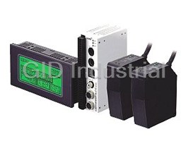
Panasonic HL-C105B-BK Sensor - CCD LASER DIF. 50+/-5MM 1MICRO CLASS-2(JIS/IEC)
Request a Quote

The quote request has been received
Close

Facing challenges or have inquiries? Feel free to contact us!
Call Us +1-469-283-2440
What they say about us
FANTASTIC RESOURCE
One of our top priorities is maintaining our business with precision, and we are constantly looking for affiliates that can help us achieve our goal. With the aid of GID Industrial, our obsolete product management has never been more efficient. They have been a great resource to our company, and have quickly become a go-to supplier on our list!
Bucher Emhart Glass
EXCELLENT SERVICE
With our strict fundamentals and high expectations, we were surprised when we came across GID Industrial and their competitive pricing. When we approached them with our issue, they were incredibly confident in being able to provide us with a seamless solution at the best price for us. GID Industrial quickly understood our needs and provided us with excellent service, as well as fully tested product to ensure what we received would be the right fit for our company.
Fuji
HARD TO FIND A BETTER PROVIDER
Our company provides services to aid in the manufacture of technological products, such as semiconductors and flat panel displays, and often searching for distributors of obsolete product we require can waste time and money. Finding GID Industrial proved to be a great asset to our company, with cost effective solutions and superior knowledge on all of their materials, it’d be hard to find a better provider of obsolete or hard to find products.
Applied Materials
CONSISTENTLY DELIVERS QUALITY SOLUTIONS
Over the years, the equipment used in our company becomes discontinued, but they’re still of great use to us and our customers. Once these products are no longer available through the manufacturer, finding a reliable, quick supplier is a necessity, and luckily for us, GID Industrial has provided the most trustworthy, quality solutions to our obsolete component needs.
Nidec Vamco
TERRIFIC RESOURCE
This company has been a terrific help to us (I work for Trican Well Service) in sourcing the Micron Ram Memory we needed for our Siemens computers. Great service! And great pricing! I know when the product is shipping and when it will arrive, all the way through the ordering process.
Trican Well Service
GO TO SOURCE
When I can't find an obsolete part, I first call GID and they'll come up with my parts every time. Great customer service and follow up as well. Scott emails me from time to time to touch base and see if we're having trouble finding something.....which is often with our 25 yr old equipment.
ConAgra Foods