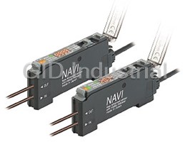
DIGITAL FIBER SENSOR
FX-100SERIES
Conforming to
EMC Directive
Bringing digital fiber sensors closer
New possibilities with digital Ţ ber sensors.
The FX series is a round 100 for success.
Easy to read, multipurpose, and at an economical price.
The FX series has been designed to be what customers want it to be.
Take a step into the new world that starts with ‘ ’.
100
Easy to read
The digital dual-display shines out in the workplace!
The digital dual-display allows you to check both the threshold
value and incident light intensity at the same time, and it also
makes the procedures for setting the various values much easier.
The threshold values can be adjusted simply by pressing the
(UP) key or the (DOWN) key, so that the sensors can
be used at the same sensitivity levels as analog control-type
Incident light intensity
Threshold value
sensors. And of course a key lock function is also included.
General purpose
Commercially-available press-Ţ t connectors are used, so that the processing costs for connection cables can be greatly reduced.
Commercially-availabie connectors
Conventional lead time
are used so that lead time and spare Conventional (cable type)
part numbers can both be reduced. ;Harness processing by outside order after sensor preparation ss p
Customer
Sensor preparation Sensor installation
The connectors used are commercially-
Harness
1 Sensor purchase and preparation
Harness Processing
available connectors, so that processing 2 Harness processing by outside order 2 processor
costs and lead time required for carrying out
From now on (built-in connector type) Lead time from now on
processing after purchase of the sensors can
;Harness processing by outside order ss p
be greatly reduced. The same connection
Customer Sensor preparation Sensor installation
Reduced
parts as the DP-100 series of digital pressure
Harness
1 Sensor purchase and preparation
Harness Processing
sensors and the PM-64 series of micro
processor
2 Harness processing by outside order 2
photoelectric sensors can be used.
Lead time further reduced
Using cables with connectors
Reduced
lead time
Customer Sensor preparation
Sensor installation Reduced
1 Purchase of sensors and cable with connectors
SUNX Ţ ber sensor product lineup
Select the best types to suit your application.
FX-300 (High function)
FX-410 (Volume setting)
Digital type
FX-101 (Standard type)
FX-100
FX-102 (Long sensing range type)
Analog control-type FX-311 (General purpose)
1
Digital fiber sensor
DIN rail
installation also
possible
"3.2 "0.126 mounting hole
9 mm Direct installation possible without bracket
0.354 in thickness
Designed in a 3-layer structure to accommodate basic settings through to
advanced settings.
Setting details are divided into three levels for clearer operation, so that settings for normal operation are
made in ‘RUN mode’, basic settings are made in ‘SET mode’, and advanced functions are set in ‘PRO mode’.
This makes setting operations much easier to understand and carry out.
RUN mode
Functions used during normal operation
[ function table ]
RUN MODE
• Changing threshold values • Key lock
• Quick settings • Code settings
Simple setting
SET mode
Functions used when initializing the
sensor and carrying out maintenance
[ function table ]
• Teaching • L-ON / D-ON setting
SET MODE
• Timer setting
• Light-emitting amount selection
• Emission frequency setting function
PRO mode
Equipped with a full complement
of digital fiber sensor functions
[ function table ]
PRO MODE
• Shift • External input • Reset
• GETA • ECO • Display reversing
• Surplus value display • Copy
Special and detailed setting
• Threshold value seeking cycle setting
The same operating system is shared by the widely-acclaimed
Digital pressure sensor
DP-100 series of digital pressure sensors. The ‘100’ is the indicator DP-100 series
for easy handling.
2
Easy for inexperienced operators to use,
and experienced operators will still be satisŢ ed too.
Introducing sensors with a full complement of functions
to support the needs of your workplace.
Changing threshold values Key lock Quick settings Code settings
Quick setting numbers (summary)
For For
For For
factory factory
designers designers
Quick code input function
operators operators
Light-emitting
No. Output operation Timer
amount selection
Sensor settings can be made simply by selecting preset
Dark-ON OFF None
values.
Dark-ON ONNone
Dark-ON OFF OFF-delay 10 ms
Dark-ON ON OFF-delay 10 ms
Light-ON ON ON-delay 40 ms
Light-ON OFF ON-delay 40 ms
Light-ON ON ON-delay 10 ms
Light-ON OFF ON-delay 10 ms
Smooth support via telephone
ConŢ rmation can be carried out smoothly via telephone by
simply quoting numbers. This can be of great assistance
when dealing with overseas customers.
3
Teaching L-ON / D-ON setting Timer setting Light-emitting amount selection Interference prevention function
For For
For
For
factory
factory
Teaching using ON / OFF buttons Light-emitting amount selection function
designers designers
operators
operators
Simply press the ON button when an object is present If the light receiving level becomes saturated when sensing
and OFF when it is not. There is no need to switch over short distances or when sensing transparent objects
settings or make judgments between Light-ON ( ) or minute objects, the light emitting amount can be adjusted
and Dark-ON ( ). so that stable sensing can be provided without needing to
change the response time.
Thru-beam type
Emission frequency setting function For For
factory factory
operators
operators
( )
Object present ON Object absent OFF
The emission frequencies can be set separately for each
unit in order to avoid interference. The emitted light ţ ashes
while setting is in progress, so that you can see at a glance
which fiber sensor is currently being set. In addition,
this interference prevention is not done by using optical
Reflective type
communication. This means that there is no need to place
the ampliŢ ers close together like there was before, and so
the ampliŢ ers can be set up apart from each other.
mWhen the emission frequencies are changed, the response times will
also change.
Object present ON Object absent OFF
Limit teaching function
This carries out teaching and sets threshold values only
when no object is present (when the incident light amount is
stable). This is useful when sensing objects if there are other
objects in the background and when sensing minute objects.
Teaching can also be carried out using external input.
Shift External input Threshold value seeking cycle setting GETA ECO Display reversing Surplus value display Copy Reset
For For
factory factory
Threshold value seeking cycle setting function External input function
operators operators
This function seeks changes in the light Settings such as emission (Brown) V
Current value
emitting amount resulting from changes halt, limit / auto teaching (Black) Output
(White) External input
in the environment over long periods and ECO settings can be
(Blue) 0 V
(such as dust levels), so that the incident carried out via external
Threshold value
light intensity can be checked at desired input. External input lines are equipped as standard
intervals and the threshold values can
be reset automatically.
Time
;Digital type
FX-300
FX-411
;Analog control-type
The functions and performance of a digital Ţ ber sensor at an
easily-affordable price!
SUNX digital-type sensors have never been more accessible than this. And they are
FX-100
target
ideal as replacement products for analog control types and teaching types also.
;Teaching type
Performance (sensing range), operability
4
Incident light intensity
(Price)
FX-100
�ORDER GUIDE
AmpliŢ ers
Accessory
Emitting
Type Appearance Model No. Output
element
• CN-14A-C2
NPN open-collector
( )
6.562 ft
FX-101 (Note 2)
transistor
mOnly include cable set type
NPN open-collector
FX-101-Z (Note 3)
transistor
PNP open-collector
FX-101P (Note 2)
transistor
PNP open-collector
FX-101P-Z (Note 3)
transistor
NPN open-collector
FX-101-CC2
transistor
PNP open-collector
FX-101P-CC2
collector transistor
Red LED
NPN open-collector
FX-102 (Note 2)
transistor
NPN open-collector
FX-102-Z (Note 3)
transistor
PNP open-collector
FX-102P (Note 2)
transistor
PNP open-collector
FX-102P-Z (Note 3)
transistor
NPN open-collector
FX-102-CC2
transistor
PNP open-collector
FX-102P-CC2
transistor
Notes: 1) The connector attached cable CN-14A-C2 is supplied with the ampliŢ er.
2) Make sure to use the optional connector attached cable CN-14A-C� or the connector CN-14A.
3) Make sure to use the optional M8 connector attached cable CN-24A-C�.
�OPTIONS
M8 connector attached cable
Designation Model No. Description M8 connector
• CN-24A-C�
attached cable
I
CN-24A-C
31.4 "4
1m 3.281 ft 1.236 "0.157
CN-14A-C1
CN-14A-C2 2
2 m 6.562 ft 0.02 mm 4-core cabtyre cable
"9
Connector
(Note)
with connector on one end "0.354 Fixing ring
attached cable
3 m 9.843 ft Cable outer diameter:"3.7 mm "0.146 in
CN-14A-C3
Protection cover
CN-14A-C5 5 m 16.404 ft
• FC-FX-1
For M8 plug-in connector type
CN-24A-C2 2m 6.562 ft
M8 connector
The connector on one end
attached cable
CN-24A-C5 5 m 16.404 ft
Cable outer diameter:"4 mm"0.157 in
Connector CN-14A Set of 10 housings and 40 contacts
AmpliŢ er mounting bracket
Protection cover This protects the operating surfaces.
FC-FX-1
• MS-DIN-4
AmpliŢ er mounting
Mounting bracket for ampliŢ er
MS-DIN-4
bracket
When it moves depending on the way it is installed on a DIN rail,
these end plates ensure that all ampliŢ ers are mounted together in Connector attached cable
End plates MS-DIN-E a secure and fully connected manner.
• CN-14A-C�
Two pcs. per set
Contact
Connector
Note: The connector attached cable CN-14A-C2 is supplied with the cable set type FX-10�(P)-CC2.
•
Housing
5
Long sensing range type Standard type
M8 plug-in M8 plug-in M8 plug-in M8 plug-in
Cable set (Note 1) Cable set (Note 1)
connector type connector type connector type connector type
FX-100
�SPECIFICATIONS
Standard type Long sensing range type
Type
Cable set Cable set
NPN output FX-101 (-Z) (Note 4) FX-101-CC2 FX-102 (-Z) (Note 4) FX-102-CC2
Item PNP output FX-101P (-Z) (Note 4) FX-101P-CC2 FX-102P (-Z) (Note 4) FX-102P-CC2
Supply voltage
12 to 24 V DC�10 % Ripple P-P 10 % or less
Normal operation: 720 mW or less (Current consumption 30 mA or less at 24 V supply voltage)
Power consumption
ECO mode: 600 mW or less (Current consumption 25 mA or less at 24 V supply voltage)
NPN open-collector transistor PNP open-collector transistor
Output • Maximum sink current:100 mA • Maximum source current: 100 mA
• Applied voltage: 30 V DC or less (between output and 0 V) Applied voltage: 30 V DC or less (between output and �V)
•
• Residual voltage: 1.5 V or less (at 100 mA sink current) • Residual voltage: 1.5 V or less (at 100 mA source current)
Output operation Selectable either Light-ON or Dark-ON, at SET mode
Short-circuit protection Incorporated
NPN non-contact input PNP non-contact input
• Signal condition • Signal condition
External input High: �8 V to �V DC or Open High: �4 V to�V DC
Low: 0 to�2 V DC (Sink current 0.5 to 3 mA)
(Source current 0.5 mA or less) Low: 0 to�0.6 V DC or Open
• Input impedance: 10 kΩ approx. • Input impedance: 10 kΩ approx.
Emission frequency 0: 250 !s or less Emission frequency 1: 2.5 ms or less
Emission frequency 1: 450 !s or less Emission frequency 2: 2.8 ms or less
Response time
Emission frequency 2: 500 !s or less Emission frequency 3: 3.2 ms or less
Emission frequency 3: 600 !s or less Emission frequency 4: 5.0 ms or less
Sensitivity setting 2-level teaching / Limit teaching / Full-auto teaching
Operation indicator Orange LED (lights up when the output is ON)
4 digits (green)�4 digits (red) LCD display
Digital display
Fine sensitivity adjustment function Incorporated
ON-delay / OFF-delay timer, switchable either effective or ineffective.
Timer function
[Timer period:1 ms, 5 ms, 10 ms, 20 ms, 40 ms, 50 ms, 100 ms, 500 ms, 1,000 ms]
Light emitting amount selection
Incorporated / Switchable either effective or ineffective
function
Incorporated Incorporated
Interference prevention
Emission frequency selection method (Note 2) Emission frequency selection method (Note 2)
function
(Functions at emission frequency 1, 2 or 3) (Functions at emission frequency 1, 2 , 3 or 4)
�10 to �55 �C �14 to �131 �F (If 4 to 7 units are mounted close together: �10 to �50 �C �14 to �122 �F, if 8 to 16 units are :
Ambient temperature
�10 to �45 �C �14 to �113 �F) (No dew condensation or icing allowed), Storage: �20 to �70 �C �4 to �158 �F
Ambient humidity 35 to 85 % RH, Storage: 35 to 85 % RH
Ambient illuminance Incandescent light: 3,000 ?x at the light-receiving face
Voltage withstandability 1,000 V AC for one min. between all supply terminals connected together and enclosure (Note 3)
Insulation resistance 20 MΩ, or more, with 250 V DC megger between all supply terminals connected together and enclosure (Note 3)
Vibration resistance 10 to 150 Hz frequency, 0.75 mm 0.030 in amplitude in X, Y and Z directions for two hours each
2
Shock resistance 98 m/s acceleration (10 G approx.) in X, Y and Z directions for Ţ ve times each
Emitting element (modulated) Red LED (Peak emission wavelength : 632 nm)
Material Enclosure: Polycarbonate, Key switch: Polycarbonate, Fiber lock lever: PBT
Connecting method Connector (Note 4)
2
Cable extension Total length up to 100 m 328.084 ft is possible with 0.3 mm , or more, cable.
Net weight: 15 g approx. Net weight: 15 g approx. Net weight: 15 g approx. Net weight: 15 g approx.
Weight
Gross weight: 35 g approx. Gross weight: 75 g approx. Gross weight: 35 g approx. Gross weight: 75 g approx.
CN-14A-C2 CN-14A-C2
Accessory
(Connector attached cable, 2 m 6.562 ft long):1pc. (Connector attached cable, 2 m 6.562 ft long):1pc.
Notes: 1) Where measurement conditions have not been speciŢ ed precisely, the conditions used were ambient temperature �23 �C �73.4 �F.
2) When using the interference prevention function, set the emission frequencies for the ampliŢ ers to be covered by the interference prevention
function to different frequency values.
However, the interference prevention function does not operate at emission frequency 0 (factory default setting) for the FX-101(P)(-Z) / FX-101(P)-CC2.
3) The voltage withstandability and the insulation resistance values given in the above table are for the ampliŢ er only.
4) Connector attached cable CN-14A-C2 is not attached to the models that have no ‘-CC2’ at the end of the model Nos.
Make sure to use the optional connector attached cable CN-14A-C� or the connector CN-14A.
Model Nos. having the sufŢ x ‘-Z’ are M8 plug-in connector type. Make sure to use the optional M8 plug-in connector cable CN-24A-C�.
6
Environmental resistance
Model No.
FX-100
�I/O CIRCUIT AND WIRING DIAGRAMS
NPN output type
FX-10�( (-Z/-CC2) )
I/O circuit diagram Terminal arrangement diagram
Terminal No. Connector type
Color code of cable with connector
(Brown) V
1
D Terminal No. Function
Load 1
(Black) Output
2 1
�V
Tr
2
100 mA max. 12 to 24 V DC
8V
ZD 2 Output
�10 % 3
(White) Extemal input
3 3 External input
4
m1
0 V
(Blue) 0 V 4
4
Internal circuit Users’ circuit
Symbols ... D : Reverse supply polarity protection diode
ZD: Surge absorption zener diode
M8 plug-in connector type
Tr : NPN output transistor
m1
Terminal No. Function
Non-voltage contact or NPN open-collector transistor
1
2 2
1 �V
or
2 Output
4 3 External input
3 3
High (�8 V to �V DC or open): Ineffective
4 0 V
Low [(0 to �2 V DC (source current 0.5 mA or less)] : Effective
PNP output type
FX-10�P( (-Z/-CC2) )
I/O circuit diagram Terminal arrangement diagram
Terminal No.
Connector type
Color code of cable with connector
(Brown) V
1
m1
Terminal No. Function
1
(White) External input
3
1
�V
2
12 to 24 V DC
ZD
100 mA max. Output
2
�10 %
3
Tr 2
3 External input
(Black) Output
4
Load
D (Blue) 0 V
4 0 V
4
Internal circuit Users’ circuit
...
Symbols D : Reverse supply polarity protection diode
ZD: Surge absorption zener diode
M8 plug-in connector type
Tr : PNP output transistor
m1
Terminal No. Function
Non-voltage contact or PNP open-collector transistor 1
2 2
1
�V
or 2 Output
4 3 External input
3 3
High [�4 V to �V DC (sink current 0.5 to 3 mA)]: Effective
4 0 V
Low (0 to �0.6 V DC or open): Ineffective
7
Sensor circuit
Sensor circuit
FX-100
�LIST OF FIBERS
Pliable Ţ bers (ţ exible and sharp bending Ţ bers) are marked with light blue in the table.
Thru-beam type (one pair set)
Fiber cable
Sensing range (mm in)(Note)
Shape of Ţ ber head Bending
Type length Model No.
(mm in) radius
Standard type FX-101� Long sensing range type FX-102�
: Free-cut
Lens mountable
M4
400 15.748 FT-B8
1,150 45.276
R25 mm
Lens mountable R0.984 in
M4
FT-FM2
Sleeve 90 mm 3.543 in
M4 Fiber
800 31.496 R25 mm FT-FM2S
300 11.811
"1.48"0.058
R0.984 in
2m
Sleeve
Sleeve 40 mm 1.575 in
M4 6.562 ft
R10 mm
FT-FM2S4
R0.394 in
"1.48"0.058
Lens mountable
M4
R1 mm
650 25.591
260 10.236 FT-W8
R0.039 in
Lens mountable M4
R4 mm
230 9.055 650 25.591 R0.157 in FT-P80
Flexible
Lens mountable
M4
1 m
R10 mm
260 10.236
800 31.496 FT-P81X
3.281 ft R0.394 in
Tough flexible
M4
Lens mountable
R4 mm
2 m
130 5.118 300 11.811 R0.157 in FT-P60
6.562 ft
Flexible
M4
215 8.465 570 22.441
W7�H9�D13.9
FT-WR80
W0.276�H0.354�D0.547 R1 mm
2m
With lens M4 R0.039 in
6.562 ft
430 16.929
1,150 45.276
W7�H9�D14.6
FT-WR80L
W0.276�H0.354�D0.575
Lens mountable
M4
R25 mm
180 7.087 430 16.929 2m FT-R80
R0.984 in
6.562 ft
Lens mountable
(except FX-LE2)
M3
800 31.496 FT-T80
300 11.811
R25 mm
R0.984 in
M3
FT-NFM2
Sleeve 90 mm 3.543 in
Fiber
M3
130 5.118 280 11.024 R25 mm FT-NFM2S
"0.88"0.035
R0.984 in
2m
Sleeve
Sleeve 40 mm 1.575 in
M3 6.562 ft
R10 mm
FT-NFM2S4
R0.394 in
"0.88"0.035
M3
R1 mm
220 8.661
80 3.150 FT-W4
R0.039 in
R4 mm
M3
80 3.150 240 9.449 R0.157 in FT-P40
Flexible
With lens
M14
R25 mm
15,000 590.550 10 m FT-FM10L
9,300 366.141
R0.984 in
32.808 ft
Note: Please take care that the sensing range of the free-cut type Ţ ber may be reduced by 20 % max. depending upon how the Ţ ber is cut.
8
Threaded type
Long sensing
M3 M4
Elbow Nut type
range g
FX-100
�LIST OF FIBERS
Pliable Ţ bers (ţ exible and sharp bending Ţ bers) are marked with light blue in the table.
Thru-beam type (one pair set)
Fiber cable
Sensing range (mm in)(Note)
Shape of Ţ ber head Bending
Type length Model No.
(mm in) radius
Standard type FX-101� Long sensing range type FX-102�
: Free-cut
With lens • Long sensing range
"3 "0.118
600 23.622 FT-WS8L
1,500 59.055
R1 mm
2m
R0.039 in
6.562 ft
"3 "0.118
150 5.906 600 23.622 FT-WS3
With lens • Long sensing range
"2.5 "0.098
2,400 94.488 FT-SFM2L
760 29.921
R25 mm
R0.984 in
"2.5 "0.098
800 31.496 2m FT-SFM2
300 11.811
6.562 ft
"2.5 "0.098
R1 mm
650 25.591
260 10.236 FT-WS8
R0.039 in
"1.5 "0.059 R25 mm
130 5.118 FT-SNFM2
280 11.024
R0.984 in
2m
6.562 ft
"1.5 "0.059
R1 mm
220 8.661
80 3.150 FT-WS4
R0.039 in
"1.5 "0.059
1m
330 12.992
120 4.724 FT-P2
3.281 ft
R4 mm
R0.157 in
"1"0.039 Flexible
500 mm
40 1.575 90 3.543 FT-PS1
19.685 in
Beam diameter
"0.25 "3
"0.125 mm "0.005 in
500 mm
"0.010""0.118
19 0.748
6 0.236 FT-E12
19.685 in
Sleeve part cannot be bent.
R5 mm
Beam diameter "0.4 "3 R0.197 in
"0.25 mm "0.010 in "0.016""0.118 1m
15 0.591 60 2.362 FT-E22
3.281 ft
Sleeve part cannot be bent.
"4 "0.157
1,000 39.370 2,350 92.520 FT-V10
3
0.118
2m
"1.5 ""0.059
6.562 ft
"2.5 "0.098
180 7.087 470 18.504 FT-SFM2SV2
0.8 8 0.031 0
Sleeve p part cannot be bent. R25 mm
"1 "0.039
R0.984 in
1 m
"2"0.079
0.6 6 0.024 0 140 5.512 FT-V22
380 14.961
3.281 ft
Sleeve part cannot be bent.
"1"0.039
"2.5"0.098
120 4.724
0.6 6 0.024 0 40 1.575 FT-V41
Sleeve part cannot be bent.
2 m
"1"0.039
6.562 ft
R1 mm
"2 "0.079
1 0.039 0 30 1.181 FT-WV42
80 3.150
R0.039 in
Sleeve part cannot be bent.
Note: Please take care that the sensing range of the free-cut type Ţ ber may be reduced by 20 % max. depending upon how the Ţ ber is cut.
9
Cylindrical type
"1
Side-view Ultra-small diameter "1.5 "0.059 "2.5 "0.098 "3"0.118
"0.039
FX-100
�LIST OF FIBERS
Pliable Ţ bers (ţ exible and sharp bending Ţ bers) are marked with light blue in the table.
Thru-beam type (one pair set)
Fiber cable
Sensing range (mm in)(Note 1)
Shape of Ţ ber head Bending
Type length Model No.
(mm in) radius
Standard type FX-101� Long sensing range type FX-102�
: Free-cut
Easy mounting • Top sensing
R1 mm
W3�H8�D12
1,200 47.244 2,800 110.236 FT-WZ8H
R0.039 in
W0.118�H0.315�D0.472
R4 mm
1,400 55.118 3,100 122.047 R0.157 in
FT-Z8H
Flexible
Easy mounting • Side sensing
R1 mm
W3�H12�D8
700 27.559 2,100 82.677
FT-WZ8E
R0.039 in
W0.118�H0.472�D0.315
2m
R4 mm
6.562 ft
800 31.496 1,850 72.835 R0.157 in FT-Z8E
Flexible
Easy mounting • Front sensing
R1 mm
950 37.402
W8.5�H12�D3 330 12.992 FT-WZ8
R0.039 in
W0.335�H0.472�D0.118
R4 mm
360 14.173 1,000 39.370 R0.157 in FT-Z8
Flexible
Front sensing
670 26.378
230 9.055
W10�H7�D2
FT-WZ4
W0.394�H0.276�D0.079
1 m
Fiber bending type
3.281 ft
W2�H10�D10 W0.079�H0.394�D0.394
80 3.150
230 9.055
FT-WZ4HB
R1 mm
Front sensing
R0.039 in
330 12.992 1,000 39.370
W14�H7�D3.5
FT-WZ7
W0.551�H0.276�D0.138
2m
Fiber bending type
6.562 ft
W3.5�H14�D11 W0.138�H0.551�D0.433
580 22.835
190 7.480
FT-WZ7HB
"""3.5
"0.138
R25 mm
3,000 118.110
1,000 39.370 FT-K8
"""3.7 R0.984 in
"0.146
Side-view type with small light
dispersion
R1 mm
700 27.559 2,200 86.614
FT-WKV8
"4"0.157 R0.039 in
2 m
3
6.562 ft
R25 mm
0.118
1,000 39.370 3,000 118.110
FT-KV8
R0.984 in
W2�H1.5�D20 W0.079�H0.059�D0.787
R10 mm
2 0.079 135 5.315 500 19.685 FT-KV1
R0.394 in
Wide area sensing
R1 mm
FT-WA30
Sensing width R0.039 in
32 mm 1.260 in
(Note 2) (No ote te 2) (Note 2) (No ote te 2)
3,500 137.795 3,500 137.795
W5�H69�D20
W0.197�H2.717�D0.787
R10 mm
FT-A30
R0.394 in
2m
Wide area sensing
6.562 ft
R1 mm
FT-WA8
Sensing g width R0.039 in
11 mm 0.433in
(Note 2) (No ote te 2)
3,500 137.795
1,500 59.055
W4.2�H31�D13.5
R10 mm
FT-A8
W0.165�H1.220�D0.531
R0.394 in
Top sensing
W5�H15�D15 W0.197�H0.591�D0.591
280 11.024 720 28.346
FT-AFM2
R25 mm
2m
Side sensing
R0.984 in
6.562 ft
240 9.449 670 26.378
FT-AFM2E
W5�H15�D15
W0.197�H0.591�D0.591
Notes: 1) Please take care that the sensing range of the free-cut type Ţ ber may be reduced by 20 % max. depending upon how the Ţ ber is cut.
2) The Ţ ber cable length practically limits the sensing range to 3,500 mm 137.795 in long.
10
Special Rectangular
Array Wide beam Narrow beam Compact
FX-100
�LIST OF FIBERS
Thru-beam type (one pair set)
Fiber cable
Sensing range (mm in)(Note 1)
Shape of Ţ ber head Bending
Type length Model No.
(mm in) radius
Standard type FX-101� Long sensing range type FX-102�
: Free-cut
350�C 662�F
Lens mountable R25 mm
M4
FT-H35-M2
R0.984 in
2 m
170 6.693 490 19.291
Fiber
6.562 ft
350�C 662�F
R25 mm
Sleeve 60 mm 2.362 in M4 R0.984 in
Sleeve FT-H35-M2S6
R10 mm
"2.1"""0.083
R0.394 in
Allows flexible wiring
200�C 392�F
1m
R10 mm
Lens mountable 100 3.937 300 11.811 FT-H20W-M1
M4
3.281 ft R0.394 in
200�C 392�F
Lens mountable 1 m
M4 210 8.268 540 21.260 FT-H20-M1
3.281 ft
R25 mm
130�C 266�F R0.984 in
Lens mountable (FX-LE2 only)
2 m
250 9.843 700 27.559 FT-H13-FM2
M4
6.562 ft
Lens mountable (FX-LE1)
FT-H20-J20-S
200 mm 7.874 in
(Note 4)
(Note 2)
M4
420 16.535 300 mm 11.811 in FT-H20-J30-S
135 5.315
(Note 2) Heat- (Note 4)
resistant
side Ţ ber
500 mm 19.685 in FT-H20-J50-S
R18 mm
(Note 2) (Note 4)
R0.709 in
Side-view
(Note 3)
FT-H20-VJ50-S
500 mm 19.685 in
(Note 2) (Note 4)
"""3.8
150 5.906
500 19.685
"0.150
"""4
800 mm 31.496 in FT-H20-VJ80-S
"0.157
(Note 2) (Note 4)
Easy mounting • Rectangular head
SEMI S2 compliant
W7�H15�D13
W0.276�H0.591�D0.512 R25 mm
520 20.472 3,100 122.047 2m FT-Z802Y
R0.984 in
6.562 ft
"5.5 "0.217
2,600 102.362
1,100 43.307 FT-L80Y
2m R30 mm
"5.5"0.217 6.562 ft R1.181 in
Side-view
(Note 5)
340 13.386 800 31.496 FT-V80Y
300�C 572�F
Lens mountable (FV-LE1/SV2 only)
1m R18 mm FT-H30-M1V-S
110 4.331
280 11.024
M4
3.281 ft R0.709 in (Note 6)
Notes: 1) Please take care that the sensing range of the free-cut type Ţ ber may be reduced by 20 % max. depending upon how the Ţ ber is cut.
2) This is the Ţ ber length (Ţ xed length) for heat-resistant side Ţ bers. The ordinary-temperature side Ţ bers are free-cut to 2 m 6.562 ft.
3) The ordinary-temperature side Ţ ber is R25 mm R0.984 in or more.
4) Heat-resistant joint Ţ bers and ordinary-temperature side Ţ bers (FT-FM2) are sold as a set. Please refer to ‘Heat-resistant joint Ţ ber catalog’ for details.
5) The allowable cutting range is 500 mm 19.685 in from the end that the ampliŢ er inserted.
6) Sold as a set comprising vacuum-resistant type Ţ ber�photo-terminal (FV-BR1)�Ţ ber at atmospheric side (FT-J8). Please refer to ‘Vacuum-resistant
Ţ ber catalog’ for details.
Model No. when ordering heat-resistant joint Ţ bers individually as replacement parts
• FT-H20-J20 (one pair set) • FT-H20-J30 (one pair set) • FT-H20-J50 (one pair set)
• FT-H20-VJ50 (one pair set) • FT-H20-VJ80 (one pair set)
Model No. when ordering vacuum-resistant Ţ bers individually as replacement parts
• Vacuum-resistant type fiber • Photo-terminal • Fiber at atmospheric side
FT-H30-M1V (one pair set) FV-BR1 (one pair set) FT-J8 (one pair set)
11
Special
Vacuum-
Chemical-resistant Heat-resistant • Joint Heat-resistant
resistant
FX-100
�LIST OF FIBERS
Pliable Ţ bers (ţ exible and sharp bending Ţ bers) are marked with light blue in the table.
Retroreţ ective type
Fiber cable
Sensing range (mm in)(Note 1, 2)
Shape of Ţ ber head Bending
Type length Model No.
(mm in) radius
Standard type FX-101� Long sensing range type FX-102�
: Free-cut
W9.5�H5.2�D15 W0.374�H0.205�D0.591
100 to 550 100 to 830
R1 mm
2m FR-WKZ11
3.937 to 21.654 3.937 to 32.677 R0.039 in
6.562 ft
W30�H30�D0.5 W1.181�H1.181�D0.020
W9.5�H5.2�D21 W0.374�H0.205�D0.827
FR-KZ21
W10.6�H28�D10.1 W0.417�H1.102�D0.398
R10 mm
200 7.874 200 7.874
2 m
W9.5�H25 R0.394 in
6.562 ft
�D5.2
FR-KZ21E
W0.374�H0.984
W10.6�H28�D10.1
�D0.205
W0.417�H1.102�D0.398
W7.5�H2.2�D11.2 W0.295�H0.087�D0.441
15 to 200 15 to 360
R10 mm
2m
FR-KV1
0.591 to 7.874 0.591 to 14.173 R0.394 in
6.562 ft
W4�H2�D21.5 W0.157�H0.079�D0.846
Notes: 1) Please take care that the sensing range of the free-cut type Ţ ber may be reduced by 20 % max. depending upon how the Ţ ber is cut.
The sensing range of FR-WKZ11 is speciŢ ed for the RF-13. The sensing range of FR-KZ21, FR-KZ21E and FR-KV1 is speciŢ ed for the attached reţ ector.
The sensing ranges when using in combination with the FR-WKZ11 reţ ector (optional) are given in the below table.
AmpliŢ er
FX-101� FX-102�
Reţ ector
FR-WKZ11�RF-210 100 to 700 3.937 to 27.559 100 to 1,100 3.937 to 43.307
FR-WKZ11�RF-220 100 to 1,300 3.937 to 51.181 100 to 2,600 3.937 to 102.362
FR-WKZ11�RF-230 100 to 2,000 3.937 to 78.740 100 to 4,000 3.937 to 157.480
2) The sensing range of FR-WKZ11 is the possible setting range for the reţ ector or reţ ective tape. The Ţ ber can detect an object less than 100 mm 3.937 in away.
However, note that if there are any white or highly-reţ ective surfaces near the Ţ ber head, reţ ected incident light may affect the Ţ ber head. If this occurs,
adjust the threshold value of the ampliŢ er unit before use.
The sensing range of FR-KZ21(E) is the possible setting range for the reţ ector. However, if setting the Ţ ber to detect objects passing within 0 to 20 mm
0 to 0.787 in from the Ţ ber head, unstable detection may result.
The sensing range of FR-KV1 is the possible setting range for the reţ ector. The Ţ ber can detect an object less than 15 mm 0.591 in away.
Reţ ective type
Fiber cable
Sensing range (mm in)(Note 1, 2)
Shape of Ţ ber head Bending
Type length Model No.
(mm in) radius
Standard type FX-101� Long sensing range type FX-102�
: Free-cut
M6
170 6.693 440 17.323
FD-B8
R25 mm
R0.984 in
Coaxial
M6
100 3.937 410 16.142
FD-FM2
Sleeve 90 mm 3.543 in
Fiber
M6
R25 mm FD-FM2S
R0.984 in
"""""2.5"0.098
100 3.937 345 13.583 2 m
Sleeve
Sleeve 40 mm 1.575 in
6.562 ft
M6
R10 mm
FD-FM2S4
R0.394 in
""""""2.5"0.098
M6
R1 mm
80 3.150
230 9.055 FD-W8
R0.039 in
R4 mm
200 7.874
90 3.543 R0.157 in FD-P80
Flexible
M6
M6
1m
R10 mm
70 2.756 220 8.661
FD-P81X
3.281 ft R0.394 in
Tough flexible
M6
R25 mm
70 2.756 180 7.087
2m FD-R80
R0.984 in
6.562 ft
Notes: 1) The sensing range is speciŢ ed for white non-glossy paper (400�400 mm 15.748�15.748 in) as the object.
2) Please take care that the sensing range of the free-cut type Ţ ber may be reduced by 20 % max. depending upon how the Ţ ber is cut.
12
Threaded type Narrow beam Sharp bending
Wafer mapping
With polarizing p
M6 Side sensing
Top sensing
Elbow
Ţ lters
FX-100
�LIST OF FIBERS
Pliable Ţ bers (ţ exible and sharp bending Ţ bers) are marked with light blue in the table.
Reţ ective type
Fiber cable
Sensing range (mm in)(Note 1, 2)
Shape of Ţ ber head Bending
Type length Model No.
(mm in) radius
Standard type FX-101� Long sensing range type FX-102�
: Free-cut
M4
110 4.331 345 13.583 FD-T80
R25 mm
R0.984 in
M4
FD-NFM2
Sleeve 90 mm 3.543 in
Fiber
M4
35 1.378 100 3.937
FD-NFM2S
R25 mm
"1.48"0.058
R0.984 in
Sleeve 40 mm 1.575 in
Sleeve
M4
R10 mm FD-NFM2S4
"1.48"0.058 R0.394 in
Sleeve 40 mm 1.575 in Fiber
R1 mm
R0.039 in
M4
15 0.591 40 1.575
2 m FD-W44
Sleeve
6.562 ft
"1.48"0.058
R10 mm
R0.394 in
M4
R1 mm
80 3.150 230 9.055
FD-WT8
R0.039 in
Small spot for sensing minute objects
R2 mm
Coaxial • Lens mountable 75 2.953
28 1.102 FD-WG4
R0.079 in
R25 mm
M4 120 4.724
50 1.969 FD-G4
R0.984 in
R4 mm
150 5.906
45 1.772 R0.157 in
FD-P60
M4 Flexible
Small diameter
R25 mm
35 1.378 100 3.937
FD-T40
R0.984 in
M3
M3
R1 mm
40 1.575
15 0.591 FD-WT4
R0.039 in
2 m
R4 mm
6.562 ft
M3
30 1.181
8 0.315 R0.157 in
FD-P40
Flexible
Lens mountable (FX-MR3, FX-MR6)
M3 R25 mm
50 1.969 120 4.724
FD-G6
R0.984 in
Coaxial
Lens mountable (FX-MR3, FX-MR6)
M3
R10 mm
160 6.299 1 m
45 1.772 FD-G6X
3.281 ft R0.394 in
Coaxial Tough flexible
(Note 3)
Coaxial • Lens mountable (FX-MR3, FX-MR6)
R25 mm
M3
18 0.709 50 1.969
FD-EG1
R0.984 in
High precision
Coaxial • Lens mountable (FX-MR3, FX-MR6)
M3
Light emitting
10 0.394 30 1.181
FD-EG2
fiber element
"0.175 "0.007
High precision
500 mm
R10 mm
Coaxial • Lens mountable (FX-MR3, FX-MR6)
19.685 in R0.394 in
M3
Light emitting
22 0.866
7 0.276 FD-EG3
fiber element
"0.125 "0.005
High precision
M3 "0.5"0.020
1 0.039 4 0.157
FD-EN500S1
Sleeve part cannot be bent.
R25 mm
Coaxial
R0.984 in
M3 "0.8"0.031
1m
15 0.591 48 1.890
FD-ENM1S1
3.281 ft
Sleeve part cannot be bent.
Notes: 1) The sensing range is speciŢ ed for white non-glossy paper [200�200 mm 7.874�7.874 in (FD-T80, FD-WT8: 400�400 mm 15.748�15.748 in, FD-W44,
FD-WT4, FD-P40, FD-G6, FD-EG1, FD-EG2, FD-EG3, FD-EN500S1, FD-ENM1S1: 100�100 mm 3.937�3.937 in)] as the object.
2) Please take care that the sensing range of the free-cut type Ţ ber may be reduced by 20 % max. depending upon how the Ţ ber is cut.
3) The allowable cutting range is 700 mm 27.559 in from the end that the ampliŢ er inserted.
13
Threaded type
M3 M4
FX-100
�LIST OF FIBERS
Pliable Ţ bers (ţ exible and sharp bending Ţ bers) are marked with light blue in the table.
Reţ ective type
Fiber cable
Sensing range (mm in)(Note 1, 2)
Shape of Ţ ber head Bending
Type length Model No.
(mm in) radius
Standard type FX-101� Long sensing range type FX-102�
: Free-cut
"3"0.118
R25 mm
100 3.937 345 13.583 FD-S80
R0.984 in
"3"0.118
R1 mm
80 3.150 230 9.055
FD-WS8
R0.039 in
2 m
Coaxial
6.562 ft
R2 mm
75 2.953
28 1.102 FD-WSG4
R0.079 in
"3"0.118
R4 mm
"3"0.118
150 5.906
45 1.772 R0.157 in FD-P50
Flexible
"2.5
R25 mm
"0.098
35 1.378 100 3.937 2 m
FD-SNFM2
R0.984 in
6.562 ft
"1.5"0.059 R4 mm
1 m
25 0.984 65 2.559
R0.157 in FD-P2
3.281 ft
Flexible
"1.5
"""0.5
"0.059"0.020
R10 mm
13 0.512
3.5 0.138
FD-E12
R0.394 in
Sleeve part cannot be bent.
1m
Coaxial
3.281 ft
"3"0.118
R25 mm
16 0.630 45 1.772
FD-E22
"0.65"0.026 R0.984 in
Sleeve part cannot be bent.
Small diameter
"""""1.5""""0.059
R25 mm
70 2.756
25 0.984 FD-V41
0.7 7 0.028 0
"3"0.118
R0.984 in
Sleeve part cannot be bent.
"""3 """2
"""""0.118 ""0.079
R1 mm
20 0.787
6 0.236 2 m
FD-WV42
1 0.039 0 R0.039 in
6.562 ft
Sleeve part cannot be bent. b
"""5 """2
""""0.197""0.079
R25 mm
30 1.181 90 3.543
FD-SFM2SV2
0.8 8 0.031 0
R0.984 in
Sleeve part cannot be bent. b
Glass substrate detection • Mapping
R25 mm
16 to 30 0.630 to 1.181 12 to 50 0.472 to 1.969 4 m
FD-L46
R0.984 in
13.123 ft
W25�H7.3�D30 W0.984�H0.287�D1.181
Glass substrate detection • Alignment
W20�H29�D3.8
0 to 40 0to1.575 0 to 50 0 to 1.969 3 m
FD-L45
W0.787�H1.142�D0.150
9.843 ft
R4 mm
Glass substrate detection • Alignment R0.157 in
0 to 19 0 to 0.748 0 to 25 0 to 0.984
W17�H29�D3.8 2 m FD-L43
W0669�H1.142�D0.150
6.562 ft
Glass substrate detection •
Seating confirmation 0 to 8 0 to 0.315
0 to 6 0 to 0.236 FD-L44
R10 mm
2m
R0.394 in
6.562 ft
0 to 4.5 0 to 0.177 0 to 5.5 0 to 0.217
W12�H19�D3 FD-L44S
W0.472�H0.748�D0.118
Glass substrate detection
7 to 12 0.276 to 0.472 6 to 13.5 0.236 to 0.531
R1 mm
FD-WL41
(Convergent point 8 0.315) (Convergent point 8 0.315) R0.039 in
3 to 14 0.118 to 0.551
1.5 to 16 0.059 to 0.630
2m FD-L41
W24�H21�D4
(Convergent point 8 0.315)
(Convergent point 8 0.315)
6.562 ft
W0.945�H0.827�D0.157
R10 mm
R0.394 in
5 to 8 0.197 to 0.315 1 to 17 0.039 to 0.669
W6�H18�D14
FD-L4
W0.236�H0.709�D0.551 (Convergent point 6 0.236) (Convergent point 6 0.236)
1 m
R1 mm
1 to 4.5 0.039 to 0.177 0.5 to 6.5 0.020 to 0.256
FD-WL48
W7.2�H7.5�D2
3.281 ft R0.039 in
W0.283�H0.295�D0.079
Notes: 1) The sensing range is specified for white non-glossy paper (FD-S80, FD-WS8: 400�400 mm 15.748�15.748 in, FD-WSG4, FD-P50, FD-SNFM2,
FD-V41, FD-SFM2SV2: 200�200 mm 7.874�7.874 in, FD-P2, FD-E12, FD-E22, FD-WV42, FD-L4, FD-WL48: 100�100 mm 3.937�3.937 in, FD-L46:
100�100�t 0.7 mm 3.937�3.937�t 0.028 in R edge of LCD glass substrates, FD-L43, FD-L44 4 and FD-L45: 100�100�t 0.7 mm 3.937�3.937� t 0.028 in
LCD glass substrates, FD-L44S: silicon wafers polished surface, FD-WL41, FD-L41: 100�100�t 2 mm 3.937�3.937�t 0.079 in glass substrates)
2) Please take care that the sensing range of the free-cut type Ţ ber may be reduced by 20 % max. depending upon how the Ţ ber is cut.
14
Rectangular Cylindrical type
"1.5 "2.5
Convergent reţ ective type Side-view Ultra-small diameter "3 "0.118
"0.059 "0.098
FX-100
�LIST OF FIBERS
Pliable Ţ bers (ţ exible and sharp bending Ţ bers) are marked with light blue in the table.
Reţ ective type
Fiber cable
Sensing range (mm in)(Note 1, 2)
Shape of Ţ ber head Bending
Type length Model No.
(mm in) radius
Standard type FX-101� Long sensing range type FX-102�
: Free-cut
Front sensing
W10�H7�D2
FD-WZ4
W0.394�H0.276�D0.079
2 to 20 0.079 to 0.787 1 to 70 0.039 to 2.756 1m
Fiber bending type
3.281 ft
W2�H �D10
FD-WZ4HB
W0.079�H0.394�D0.394 R1 mm
Front sensing
R0.039 in
1 to 55 0.039 to 2.165 160 6.299
W14�H7�D3.5
FD-WZ7
W0.551�H0.276�D0.138
2m
Fiber bending type
6.562 ft
0.5 to 180 0.020 to 7.087
1 to 60 0.039 to 2.362
W3.5�H14�D11
FD-WZ7HB
W0.138�H0.551�D0.433
Long sensing range • Rectangular head
20 to 480
R1 mm
20 to 180 0.787 to 7.087 2 m
FD-WKZ1
W5.2� 5�D15
0.787 to 18.898 R0.039 in
6.562 ft
W0.205�H0.374�D0.591
R25 mm
125 4.921 250 9.843
2m FD-A15
R0.984 in
6.562 ft
W7�H15�D30 W0.276�H0.591�D1.181
Top sensing
285 11.220
105 4.134
FD-AFM2
W5 H20�D20
W0.197�H0.787�D0.787 R25 mm
2 m
Side sensing
R0.984 in
6.562 ft
85 3.346 245 9.646
FD-AFM2E
W5 H20�D20
W0.197�H0.787�D0.787
Protective tube
Contact type
R40 mm
"6 "0.236
2 m R1.575 in
FD-F8Y
Fiber
6.562 ft
R15 mm
(Note 3)
R0.591 in
Mountable on pipe •
Applicable pipe diameter:
Standard
Outer dia."6 to "26 mm"0.236 to "1.024 in transparent pipe
FD-F41
W25�H13�D20
[PVC (vinyl chloride), ţ uorine resin, polycarbonate, acrylic, glass, wall thickness 1 to 3 mm 0.039 to 0.118 in]
W0.984�H0.512�D0.787
R10 mm
2 m
Mountable on pipe • For PFA, wall
R0.394 in
Applicable pipe diameter:
6.562 ft
thickness 1 mm 0.039 in pipe
Outer dia."6 to "26 mm"0.236 to "1.024 in transparent pipe FD-F4
W25�H13�D20
[PFA (ţ uorine resin) or equivalently transparent pipe, wall thickness 1 mm 0.039 in]
W0.984�H0.512�D0.787
Notes: 1) The sensing range is speciŢ ed for white non-glossy paper [200�200 mm 7.874�7.874 in (FD-WKZ1, FD-AFM2, FD-AFM2E: 400�400 mm 15.478�15.478 in)]
as the object.
2) Please take care that the sensing range of the free-cut type Ţ ber may be reduced by 20 % max. depending upon how the Ţ ber is cut.
3) The allowable cutting range is 1,000 mm 39.370 in from the end that the ampliŢ er inserted.
15
Special Rectangular
Long sensing
Liquid level sensing Array Wide beam Compact
range g g
FX-100
�LIST OF FIBERS
Reţ ective type
Fiber cable
Sensing range (mm in)(Note 1, 2)
Shape of Ţ ber head Bending
Type length Model No.
(mm in) radius
Standard type FX-101� Long sensing range type FX-102�
: Free-cut
350�C 662�F • Coaxial
R25 mm
M6
FD-H35-M2
R0.984 in
2m
75 2.953 280 11.024
Fiber
350�C 662�F • Sleeve 60 mm 2.362 in 6.562 ft
R25 mm R0.984 in
"""2.8
Sleeve
FD-H35-M2S6
M6 ""0.110
R10 mm
R0.394 in
200�C 392�F • Coaxial
R25 mm
M6
120 4.724 300 11.811
FD-H20-M1
R0.984 in
Fiber
350�C 662�F • Sleeve 90 mm 3.543 in
R25 mm R0.984 in
1m
Sleeve
200 7.874
85 3.346 FD-H35-20S
3.281 ft
"""2.1 R10 mm
M4
"0.083 R0.394 in
200�C 392�F • Coaxial
90 3.543 280 11.024
FD-H20-21
M4
300�C 572�F • Glass substrate detection
Convergent reflective type
2 m
W19�H27�D5 0 to 17 0 to 0.669
2 to 9 0.079 to 0.354
FD-H30-L32
6.562 ft
W0.748�H1.063
�D0.197
R25 mm
180�C 356�F • Glass substrate detection
R0.984 in
Convergent reflective type y y y
W19�H27�D5
0 to 10 0 to 0.394 0 to 25 0 to 0.984
FD-H18-L31
W0.748�H1.063
�D0.197
2 m
130�C 266�F
6.562 ft
M6
100 3.937 280 11.024
FD-H13-FM2
300�C 572�F • Rectangular head
W9.5�H5.2�D15 W0.374�H0.205�D0.591
FD-H30-KZ1V-S
1m
25 to 80 0.984 to 3.150 10 to 220 0.394 to 8.661
3.281 ft (Note 3)
R18 mm
300�C 572�F • Glass substrate detection
R0.709 in
Convergent reflective type
3 m FD-H30-L32V-S
W19�H5�D27
0 to 11 0 to 0.433
2.5 to 6.5 0.098 to 0.256
W0.748�H0.197 9.843 ft
(Note 3)
�D1.063
Notes: 1) The sensing range is speciŢ ed for white non-glossy paper [400�400 mm 15.748�15.748 in (FD-H30-L32, FD-H18-L31: 50�50 mm 1.969�1.969 in
glass substrate, FD-H30-KZ1V-S, FD-H30-L32V-S: 100�100�t 0.7 mm 3.937�3.937�t 0.028 in transparent glass)] as the object.
2) Please take care that the sensing range of the free-cut type Ţ ber may be reduced by 20 % max. depending upon how the Ţ ber is cut.
3) Sold as a set comprising vacuum-resistant type Ţ ber�photo-terminal (FV-BR1)�Ţ ber at atmospheric side (FT-J8).
Model No. when ordering vacuum-resistant Ţ bers individually as replacement parts
• Vacuum-resistant type fiber • Mounting bracket for FD-H30-KZ1V • Photo-terminal • Fiber at atmospheric side
FD-H30-KZ1V MS-FD-2 FV-BR1 (one pair set) FT-J8 (one pair set)
FD-H30-L32V
Accessories (attached with Ţ bers)
RF-003 (FR-KZ21/KZ21E exclusive reflector)
• RF-003 • RF-13 • FX-CT1 • FX-CT2
RF-13 (Reflective tape)
FX-CT1 (Fiber cutter)
FX-CT2 (Fiber cutter)
FX-AT2 (Attachment for fixed-length fiber, Orange)
FX-AT3 (Attachment for "2.2 mm"0.087 in fiber, Clear orange)
FX-AT4 (Attachment for "1 mm "0.039 in fiber, Black)
FX-AT5 (Attachment for "1.3 mm"0.051 in fiber, Gray)
FX-AT6 (Attachment for "1 mm "0.039 in / "1.3 mm"0.051 in mixed fiber, Black / Gray)
• FX-AT2 • FX-AT3 • FX-AT4
If connecting to a Ţ ber ampliŢ er other than the
FX-100 series
Applicable fiber amplifiers: FX2 // FX3 series
FX-AT10 (Attachment for "1 mm"0.039 in fiber)
FX-AT13 (Attachment for "1.3 mm "0.051 in fiber)
FX-AT15 (Attachment for "1 mm "0.039 in / "1.3 mm"0.051 in mixed fiber)
• FX-AT10 • FX-AT5 • FX-AT6
• FX-AT13
• FX-AT15
16
Special
Vacuum-resistant Heat-resistant
FX-100
�FIBER OPTIONS
Lens (For thru-beam type Ţ ber)
Designation Model No. Description
Increases the sensing
Sensin Sensing range (mm) [Lens on both sides] g range (mm) [Lens on both sides]
range by 5 times or more.
AmpliŢ er
FX-101� FX-102�
Fiber
• Ambient temperature:
FT-B8 2,200 2,200 3 3,500 ,500 ( (Note 2) Note 2)
�60 to �350 °C FT-FM2, FT-T80 3,000 3,000 3, 3,500 500 ( (Note 2) Note 2)
Expansion
FT-R80 1,900 1,900 3 3,500 ,500 ( (Note 2) Note 2)
�76 to �662 °F
lens FT-W8 3 3,000 ,000 3 3,500 ,500 ( (Note 2) Note 2)
FX-LE1
FT-P80, FT-P60 3 3,500 ,500 ( (Note 2) Note 2) 3 3,500 ,500 ( (Note 2) Note 2)
(Note 1)
FT-P81X 1,600 1,600 ( (Note 2) Note 2) 1,600 1,600 ( (Note 2) Note 2)
FT-H35-M2 2,000 2,000 3, 3,500 500 ( (Note 2) Note 2)
FT-H20W-M1 1,300 1,300 1,600 1,600 ( (Note 2) Note 2)
FT-H20-M1 1,600 1,600 ( (Note 2) Note 2) 1,600 1,600 ( (Note 2) Note 2)
FT-H20-J20-S,, FT-H20-J30-S,, FT-H20-J50-S 1 1,000 ,000 3, 3,500 500 ( (Note 2) Note 2)
Tremendously increases the
Sensin Sensing range (mm) [Lens on both sides] g range (mm) [Lens on both sides]
sensing range with large
AmpliŢ er
FX-101� FX-102�
diameter lenses.
Fiber
Super-
FT-B8,,, FT-FM2, FT-R80,, FT-W8,, FT-P80,, FT-P60 3 3,500 ,500 ( (Note 2) Note 2) 3 3,500 ,500 ( (Note 2) Note 2)
expansion
FT-P81X 1 1,600 ,600 ( (Note 2) Note 2) 1 1,600 ,600 ( (Note 2) Note 2)
FX-LE2 • Ambient temperature:
lens
FT-H35-M2 3 3,500 ,500 ( (Note 2) Note 2) 3 3,500 ,500 ( (Note 2) Note 2)
�60 to �350 °C
(Note 1)
FT-H20W-M1, FT-H20-M1 1,600 1,600 ( (Note 2) Note 2) 1,600 1,600 ( (Note 2) Note 2)
�76 to �662 °F
FT-H13-FM2 3 3,500 ,500 ( (Note 2) Note 2) 3 3,500 ,500 ( (Note 2) Note 2)
FT-H20-J20-S,,, FT-H20-J30-S, FT-H20-J50-S 3 3,500 ,500 ( (Note 2) Note 2) 3 3,500 ,500 ( (Note 2) Note 2)
Beam axis is bent by 90 °.
Sensing range (mm) [Lens on both sides Sensing range (mm) [Lens on both sides] ]
AmpliŢ er
FX-101� FX-102�
• Ambient temperature:
Fiber
�60 to �300 °C
FT-B8 530 530 1,45 1,450 0
�76 to �572 °F FT-FM2, FT-T80 550 550 1,70 1,700 0
FT-W8 45 450 0 1,300 1,300
Side-view
FX-SV1 FT-P80 42 420 0 1,40 1,400 0
lens
FT-P60 300 300 850 850
FT-P81X 5 550 50 1,70 1,700 0
FT-H35-M2 2 280 80 800 800
FT-H20W-M1 1 140 40 4 400 00
FT-H20-M1 2 280 80 8 840 40
FT-H20-J20-S,,, FT-H20-J30-S, FT-H20-J50-S 1 150 50 41 410 0
Sensing range increases by
Sensin Sensing range (mm) [Lens on both sides] (Note 3) g range (mm) [Lens on both sides] (Note 3)
Expansion
4 times or more.
AmpliŢ er
lens for vacuum-
FV-LE1 FX-101� FX-102�
• Ambient temperature: Fiber
resistant Ţ ber
FT-H30-M1V 45 450 0 1,60 1,600 , 0
(Note 1) �40 to �120 °C �40 to�248 °F
Beam axis is bent by 90 °.
Sensin Sensing range (mm) [Lens on both sides] (Note 3) g range (mm) [Lens on both sides] (Note 3)
Side-view
AmpliŢ er
lens for
FX-SV2 FX-101� FX-102�
• Ambient temperature: Fiber
vacuum-
FT-H30-M1V 4 450 50 1,60 1,600 , 0
resistant Ţ ber �60 to �300 °C �140 to�572 °F
Notes: 1) Be careful when installing the thru-beam type Ţ ber equipped with the expansion lens, as the beam envelope becomes narrow and alignment is difŢ cult. Especially
when installing a Ţ ber with many cores (sharp bending Ţ bers and heat-resistant glass Ţ ber), please be sure to use it only after you have adjusted it sufŢ ciently.
2) The Ţ ber cable length practically limits the sensing range to 3,500 mm 137.795 in long (FT-H20W-M1, FT-P81X X and FT-H20-M1: 1,600 mm 62.992 in).
3) The Ţ ber cable length for the FT-H30-M1V V is 1m 3.281 ft. The sensing ranges in FX-102� (long sensing range type) take into account the length of the FT-J8 atmospheric side Ţ ber.
Lens (For reţ ective type Ţ ber)
Designation Model No. Description
Pinpoint spot of "0.5 mm"0.020 in. Enables detection of minute objects or small marks.
Pinpoint spot
• Distance to focal point: 6�1 mm 0.236 � 0.039 in • Applicable Ţ bers: FD-WG4, FD-G4
FX-MR1
lens
• Ambient temperature:�40 to�70 °C �40 to�158 °F
The spot diameter is adjustable from 0.7 mm
"
Sensing range for FX-101� (Note)
S Screw-in crew-in
to 2 mm 0.028 in to 0.079 in according to
" " "
dept depth h
Screw-in depth Distance to focal point Spot diameter
how much the Ţ ber is screwed in.
7mm 18.5 mm approx. "0.7 mm
Zoom lens FX-MR2
Applicable Ţ bers: FD-WG4, FD-G4
•
12 mm 27 mm approx. "1.2 mm
Distance t Distance to o
• Ambient temperature:�40 to�70 °C �40 to�158 °F
ffocal point ocal point 14 mm 43 mm approx "2.0 mm
Sp Spot ot
Accessory: MS-EX-3 (mounting bracket)
•
d diameter iameter
Extremely Ţ ne spot of 0.3 mm 0.012 in
" " Sensing range for FX-101� (Note)
approx. achieved.
Fiber model No. Distance to focal point Spot diameter
Applicable Ţ bers: FD-WG4, FD-G4,
•
Finest spot FD-EG3 7.5�0.5 mm "0.15 mm approx.
FX-MR3
FD-EG1, FD-EG2, FD-EG3, FD-G6X, FD-G6
lens
FD-EG2 7.5�0.5 mm "0.2 mm approx.
Ambient temperature:
•
FD-EG1 7.5�0.5 mm "0.3 mm approx.
�40 to�70 °C �40 to�158 °F
FD-WG4/G4/G6X/G6 7.5�0.5 mm "0.5 mm approx.
Distance to
focal point Extremely Ţ ne spot of 0.1 mm 0.004 in
" " Sensing range for FX-101� (Note)
approx. achieved.
Fiber model No. Distance to focal point Spot diameter
Spot diameter
Applicable Ţ bers: FD-WG4, FD-G4,
•
Finest spot FD-EG3 7.5�0.5 mm "0.1 mm approx.
FX-MR6
FD-EG1, FD-EG2, FD-EG3, FD-G6X, FD-G6
lens
FD-EG2 7.5�0.5 mm "0.15 mm approx.
Ambient temperature:
•
FD-EG1 7.5�0.5 mm "0.2 mm approx.
�20 to�60 °C �4 to�140 °F
FD-WG4/G4/G6X/G6 7.5�0.5 mm "0.4 mm approx.
Screw-in depth
FX-MR2 is converted into a side-view type Sensing range for FX-101� (Note)
and can be mounted in a very small space.
Zoom lens Screw-in depth Distance to focal point Spot diameter
Applicable Ţ bers: FD-WG4, FD-G4
•
Side-view FX-MR5 Distance nce 8 mm 13 mm approx. "0.5 mm
to foca al Ambient temperature:
type • 10 mm 15 mm approx.
( ( ) "0.8 mm
point
�40 to�70 °C �40 to�158 °F 14 mm 30 mm approx "3.0 mm
Spot diameter
Note: The sensing ranges are the values when used in combination with FX-101� (standard type). Please contact our ofŢ ce for details on sensing ranges for other types of ampliŢ er.
17
For reţ ective type Ţ ber For thru-beam type Ţ ber
FX-100
�FIBER OPTIONS
Others
Protective tube
Designation Model No. Description
• FTP-�
• FDP-�
FTP-500 (0.5 m 1.640 ft)
FT-B8 FT-P80
For
FT-FM2 FT-P60
FTP-1000 (1 m 3.281 ft) M4
FT-FM2S FT-FM2S4
thread
Protective tube Fiber bender
FTP-1500 (1.5 m 4.921 ft) FT-H13-FM2
For thru-beam • FB-1
( ( type Ţ ber ) FTP-N500 (0.5 m 1.640 ft) FT-T80 FT-P40
For
FT-NFM2 FD-T40
M3
FTP-N1000 (1 m 3.281 ft)
FT-NFM2S FD-P40
The protective tube, made
thread
FT-NFM2S4 of non-corrosive stainless
FTP-N1500 (1.5 m 4.921 ft)
steel, protects the inner
FDP-500 (0.5 m 1.640 ft)
FD-B8 FD-P80 Ţ ber cable from any
Fiber cutter
For
external forces.
FD-FM2 FT-H13-FM2
• FX-CT2
FDP-1000 (1 m 3.281 ft) M6
FD-FM2S
thread
Protective tube
FD-FM2S4
FDP-1500 (1.5 m 4.921 ft)
For reţ ective
( ( type Ţ ber ) FDP-N500 (0.5 m 1.640 ft) FD-T80
For
FD-NFM2
M4
FDP-N1000 (1 m 3.281 ft)
FD-NFM2S
thread
FD-NFM2S4
FDP-N1500 (1.5 m 4.921 ft)
• FX-CT1
The Ţ ber bender bends the sleeve part of the Ţ ber head at the
Fiber bender FB-1
proper radius. (Note 1)
MS-AJ1-F Horizontal mounting type
Universal sensor
Mounting stand assembly for Ţ ber
mounting stand
(For M3, M4 or M6 threaded head Ţ ber)
(Note 2)
Vertical mounting type
MS-AJ2-F
Universal sensor mounting stand
Using the arm which enables adjustment in
FX-CT2
The free-cut type Ţ ber can be easily cut.
the horizontal direction, sensing can also
Fiber cutter Accessory. FX-CT1 is attached with the FT-P80 or the FD-P80.
be done from above an assembly line.
The FX-CT2 is provided with Ţ bers other than this.
FX-CT1
360 ° rotation
• MS-AJ1-F
Forward / back
Attachment for This is the attachment for the Ţ xed length Ţ ber. Orange.
FX-AT2 adjustment: 130 mm
Ţ xed-length Ţ ber (Accessory)
5.118 in approx.
Height
Attachment for "2.2 mm This is the attachment for the "2.2 mm"0.087 in Ţ ber. Clear Orange.
adjustment:
FX-AT3
"0.087 in Ţ ber (Accessory. Does not attach with the FT-P80 or the FD-P80.) 150 mm
5.906 in
approx.
Attachment for "1 mm This is the attachment for the"1 mm "0.039 in Ţ ber. Black.
360 °
FX-AT4
20 2 2 2 °
"0.039 in Ţ ber (Accessory) rotation
Mounting hole
20 °
for M6 screw
Angle adjustment:�20 °
Attachment for "1.3 mm This is the attachment for the"1.3 mm"0.051 in Ţ ber. Gray.
FX-AT5
"0.051 in Ţ ber (Accessory)
360 ° rotation
• MS-AJ2-F
Attachment for "1mm
This is the attachment for the "1mm"0.039 in / "1.3 mm"0.051 in
Forward / back
"0.039 in / "1.3 mm FX-AT6
mixed Ţ ber. Black / Gray. (Accessory) adjustment: 130 mm
"0.051 in mixed Ţ ber
5.118 in approx.
Height
adjustment:
Notes: 1) Do not bend the sleeve part of any side-view type Ţ ber or ultra-small diameter head type Ţ ber.
150 mm
2) Refer to the ‘Sensor general catalog 2003-2004’ or the SUNX website: http://www.sunx.jp/ for universal sensor mounting stand.
5.906 in
approx.
360 °
20 2 2 2 ° ° Mounting hole
rotation
for M6 screw
20 °
Fiber attachment
Angle adjustment:�20 °
It’s possible to simultaneously cut two fibers to the same length
Each fiber (with some exceptions) has a newly developed two-in-one fiber attachment (FX-AT3/AT4/AT5/AT6) which enables two fibers to be
cut simultaneously to the same length with the new fiber cutter (FX-CT2). Also, since the fibers can be attached to the amplifier while being
fixed in position in the two-in-one fiber attachment, sensitivity changes resulting from variation in the amount of fiber insertion do not occur.
• FX-AT2 • FX-AT3 • FX-AT4 • FX-AT5 • FX-AT6
For fixed-length For"2.2 mm For"1 mm For"1.3 mm For"1 mm "0.039 in /
fiber "0.087 in fiber "0.039 in fiber "0.051 in fiber "1.3 mm "0.051 in mixed fiber
�PRECAUTIONS FOR PROPER USE
ON key / OFF key /
Part description
• Never use this product as a sensing device for personnel protection. Set value UP key Set value DOWN key
Operation indicator
• In case of using sensing devices for personnel protection, use products
MODE key
(Orange)
which meet regulations and standards, such as OSHA, ANSI or IEC
etc., for personnel protection applicable in each region or country.
Digital display (Red)
Digital display (Green)
(Incident light intensity)
(Threshold value)
18
Applicable Ţ bers
�DIMENSIONS (Unit: mm in) The CAD data in the dimensions can be downloaded from the website: http://www.sunx.jp/
AmpliŢ er AmpliŢ er
FX-101�, FX-102� FX-101(P)-Z, FX-102(P)-Z
6 0.236 6 0.236
6 6 10.85
47 1.850
0.236 0.236 0.427
29 1.142 47 47 18 1.850 50
0.8 2.7 0.7
20
12.2 29 29 1 1.142 142
0.031 0.106 0.106 0 0.028
0.480 0.787 0.787 7 12.2
0.8
0.480
0.031 0
0.7 0.028
OFF key / Setting value DOWN key
4.1
0.161 ON key / Setting value UP key
Operation indicator (Orange) Operation indicator (Orange) OFF key / Setting value DOWN key
4.1
2.7
0.161
Digital display (Green, Red) MODE key
0.106
ON key / Setting value UP key
Digital display (Green, Red)
MODE key
Assembly dimensions with optional protective cover
9
0.354 1.1 1
0.75 0.030
0.043 0.039
7
"6.5
0.276
"0.256
9
66.2
2 0.079 4 30
10
0.354
2.606
0.157 1.181 .18
0.394
2 0.079
10
6 0.236
0.394
7
0.276 0.8 ""3.2
1.1
3.2
0.031 ""0.126
8.1
0.043 30 3
0.126
10
0.319
1.181 0.118 2 2
0.394
3 0.118
5.5
0.079 0
10 50 50 1.969 1.969
8.1
0.217
0.394
0.319
13.5
35 35 1.378 1 378
"3.2
0.531
3.2
""0.126
4 64.5 64.5 2.539 2.539
0.126 0
0.157 Suitable for 35 mm 1.378 in width DIN rail
2
0.0 079
5.5 0.217 50 1.969
13.5
35 1.378
0.531
64.5 2.539
Suitable for 35 mm 1.378 in width DIN rail
MS-DIN-4 Amplifer mounting bracket (Optional) MS-DIN-E End plate (Optional)
"7.2 mm "0.283 in "3.2"0.126 7.2 mm 0.283 in
3.2
sppg ot facing, 4 0.157 deep p p 0.126 spot facing, 4 0.157 deep
M3 (Iength 18 mm 0.709 in) pan head screws
2.75 0.108
60
3 3 0.118
2.362
M3 Square nut
0.118
15 5.6
1
0.591 0.220
0.039
9.25 15
0.364 0.591
6.2 mm 0.244 in
24.7
spot facing, 3 0.118 deep
"6.2 mm "0.244 in
0.972
spot facing, 3 0.118 deep
9
3.2
"3.2"0.126
0.354
0.126
1.6 32
4
11.5 0.063 1.260
0.157
0.453
Suitable for 35mm 1.378 in width DIN rail
Material: Polycarbonate
4 1
0.157 0.039
24.5
5
0.965
0.197
35
1.378
Material: PBT
Connector attached cable (Optional)
CN-14A-C�
CN-14A-C2 is attached FX-101(P)-CC2 / FX-102(P)-CC2
L
50 50 50
35 35 35
• Length L
( ) () ( ) ()
1 1.969 969
1 13 .378 78
8
8 Model No. Length L (mm in)
( ) ( ( ) )
( ) ( ( )
CN-14A-C1 1,000 39.370
CN-14A-C2 2,000 78.740
CN-14A-C3 3,000 118.110
"3.7"0.146 cable
CN-14A-C5 5,000 196.850
All information is subject to change without prior notice.
SUNX Limited
2431-1 Ushiyama-cho, Kasugai-shi, Aichi,
486-0901, Japan
Phone: +81-(0)568-33-7211
FAX: +81-(0)568-33-2631
Overseas Sales Dept.
Phone: +81-(0)568-33-7861
http://www.sunx.jp/
FAX: +81-(0)568-33-8591
Printed on 100% recycled paper PRINTED IN JAPAN
No.CE-FX100-10 January, 2007


 Manufacturers


What they say about us
FANTASTIC RESOURCE
One of our top priorities is maintaining our business with precision, and we are constantly looking for affiliates that can help us achieve our goal. With the aid of GID Industrial, our obsolete product management has never been more efficient. They have been a great resource to our company, and have quickly become a go-to supplier on our list!
Bucher Emhart Glass
EXCELLENT SERVICE
With our strict fundamentals and high expectations, we were surprised when we came across GID Industrial and their competitive pricing. When we approached them with our issue, they were incredibly confident in being able to provide us with a seamless solution at the best price for us. GID Industrial quickly understood our needs and provided us with excellent service, as well as fully tested product to ensure what we received would be the right fit for our company.
Fuji
HARD TO FIND A BETTER PROVIDER
Our company provides services to aid in the manufacture of technological products, such as semiconductors and flat panel displays, and often searching for distributors of obsolete product we require can waste time and money. Finding GID Industrial proved to be a great asset to our company, with cost effective solutions and superior knowledge on all of their materials, it’d be hard to find a better provider of obsolete or hard to find products.
Applied Materials
CONSISTENTLY DELIVERS QUALITY SOLUTIONS
Over the years, the equipment used in our company becomes discontinued, but they’re still of great use to us and our customers. Once these products are no longer available through the manufacturer, finding a reliable, quick supplier is a necessity, and luckily for us, GID Industrial has provided the most trustworthy, quality solutions to our obsolete component needs.
Nidec Vamco
TERRIFIC RESOURCE
This company has been a terrific help to us (I work for Trican Well Service) in sourcing the Micron Ram Memory we needed for our Siemens computers. Great service! And great pricing! I know when the product is shipping and when it will arrive, all the way through the ordering process.
Trican Well Service
GO TO SOURCE
When I can't find an obsolete part, I first call GID and they'll come up with my parts every time. Great customer service and follow up as well. Scott emails me from time to time to touch base and see if we're having trouble finding something.....which is often with our 25 yr old equipment.
ConAgra Foods