

 Manufacturers
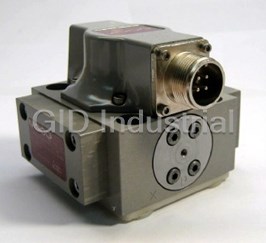
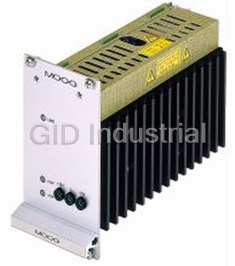
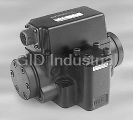
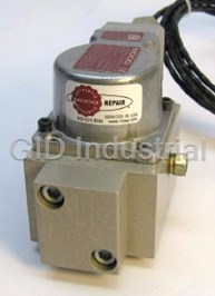
MOOG N121-001A

Description
Moog N121-001A Series Dual Transducer Servocontrollers
Part Number
N121-001A
Price
Request Quote
Manufacturer
MOOG
Lead Time
Request Quote
Category
TBD
Datasheet

Extracted Text
N121-001A Series SPECIFICATIONS Servoamplifier Transducer Demodulator Dual Transducer Servocontroller Servovalve Drive: Outputs: ±8 mA into 1,250 Ω 4 to 20 mA (monitor transducer demodulated Input Command: signals & selected feedback) 4 to 20 mA ungrounded current loop Ripple: ≤ 10 mVrms @ twice the Proportional Gain: excitation frequency 1.0 to 47 mA/V Linearlty: Integral Gain: ≤ ±0.2% at 3 kHz (preliminary) 0.5 to 250 mA/V-sec Gain Stability: Differential Gain: ±250 ppm gain/°C, ±0.1 mV/°C 0.04 to 4 mA-sec/V Frequency Response: Frequency Response: negligible phase lag @ 10 Hz, ≤ 3 dB amplitude ≥ 800 Hz ≤ 10° phase lag @ 100 Hz (1 Henry load) The N121-001A Series Dual Transducer Servocontroller was developed specifically for General Electric gas and steam turbine upgrades and modifications.This circuit card is designed to interface with various manufacturers’ turbine controlllers, existing or new intrinsically safe servovalves and redundant position feedback transducers. Specifically, the N121-001A contains current drivers for driving triple redundant servovalve coils, redundant excitation/demodulation circuits for dual position feedback transducers, a comparator high select circuit, and 4 to 20 mA interface circuits. Form Factor: Transducer Exciter Snap Trac format 3.25" x 19" Frequency: 2,000 to 4,000 Hz Weight: 2.5 lb Amplitude: 0.7 to 8 Vrms K1 Relay Contact Rating Amplitude Stability: Consumption: ≤ 250 ppm amplitude/°C 15 mA @ 24 VDC (preliminary) Contact Rating: 2.50 mA / 175 VDC / 3 watt Built-In Power Regulator Power Input: Coil Resistance: 110/220 VAC ±10%, 50/60 Hz, 30 VA 2 KΩ @ 20°C Max Pick-up VDC @ 20°C: Temperat ur e R ange: 18.0 VDC 0°C to 50°C Max Drop-up VDC @ 20°C: 2.0 VDC FEATURES ➢ Closed-loop control of redundant linear transducer position loops. ➢ PID control; jumper selectable with independent gain potentiometers. ➢ Linear transducer signal high selection circuit. ➢ Current limiter (rate limit control possible). ➢ 4 to 20 mA input for position command signal. ➢ 4 to 20 mA outputs to monitor the position feedback signals. ➢ SPDT relay section - jumper selectable Hi (+5 to 15 VDC) or Low (0 VDC) activation logic state. N121-001A SERVOCONTROLLER BLOCK DIAGRAM TURBINE CONTROLLER N121-001A DUAL TRANSDUCER SERVOCONTROLLER CONTROL VALVE COMMAND BIAS A 1K B COMMAND TRIM ERROR 1K P COMMAND E CURRENT CURRENT BUFFER I 4 TO 20 MA LIMITER DRIVER F D C INTEGRATOR D RESET MONITOR CURRENT LIMIT SYSTEM BIAS K1 RELAY FEEDBACK BUFFER 4 TO 20 MA FREQUENCY AMPLITUDE TRANSDUCER 1 COMPARATOR HIGH SELECT OSCILLATOR POWER CIRCUIT AMP SPAN MONITOR TRANSDUCER 1 BUFFER DEMODULATOR 4 TO 20 MA ZERO FREQUENCY AMPLITUDE TRANSDUCER 2 OSCILLATOR POWER AMP SPAN MONITOR TRANSDUCER 2 DEMODULATOR BUFFER 4 TO 20 MA ZERO POWER SUPPLY 110/220 VAC +/- 10%, 50/60 Hz CUSTOMER INTERCONNECT DIAGRAM AND SET-UP 110 VAC POWER HOOKUP SERVO COIL HOOK-UP TEST POINT DESCRIPTION POTENTIOMETER DESCRIPTION J1 J3 P1 PROPORTIONAL COMPENSATION GAIN ADJUST TP1 ERROR SIGNAL P2 INTEGRAL COMPENSATION GAIN ADJUST TP2 PROPORTIONAL COMPENSATION SIGNAL 110 VAC POWER INPUT 1 SERVOVALVE COIL -1 SIGNAL (+) CURRENT LOOP OUTPUT 1 P3 DIFFERENTIAL COMPENSATION LPF ADJUST SERVOVALVE COIL -2 SIGNAL (+) CURRENT LOOP OUTPUT TP3 INTEGRAL COMPENSATION SIGNAL 2 110 VAC POWER INPUT 2 SERVOVALVE COIL -1 SIGNAL (-) CURRENT LOOP OUTPUT P4 DIFFERENTIAL COMPENSATION GAIN ADJUST 3 JUMPER TO J1-1 3 TP4 SERVOVALVE CURRENT VOLTAGE DRIVE SIGNAL 4 4 SERVOVALVE COIL -2 SIGNAL (-) CURRENT LOOP OUTPUT P5 CURRENT LIMIT ADJUST JUMPER TO J1-2 TP5 SERVOVALVE CURRENT RETURN SENSE SIGNAL 5 MONITOR LT-1 SIGNAL (+) CURRENT LOOP OUTPUT P6 POSITIVE REGULATOR (+15) ADJUST 5 CHASSIS GROUND TP6 DIFFERENTIAL COMPENSATION SIGNAL MONITOR LT-1 SIGNAL (-) CURRENT LOOP OUTPUT 6 P7 NEGATIVE REGULATOR (-15) ADJUST TP7 SUMMED COMPENSATION SIGNAL MONITOR FEEDBACK (+) CURRENT LOOP OUTPUT 7 P8 BIAS ADJUST TP8 NULL BIAS CURRENT POT (P17) MONITOR SIGNAL 8 MONITOR FEEDBACK (-) CURRENT LOOP OUTPUT P9 LT-1 DEMODULATOR SPAN ADJUST TP9 +V POSITIVE UNREGULATED VOLTAGE N.C. 9 P10 LT-1 DEMODULATOR ZERO ADJUST TP10 +E POSITIVE REGULATED VOLTAGE 10 N.C. 220 VAC POWER HOOKUP P11 LT-1 EXCITATION FREQUENCY ADJUST TP11 -E NEGATIVE REGULATED VOLTAGE J1 P12 LT-1 EXCITATION SYMMETRY ADJUSTMENT TP12 -V NEGATIVE UNREGULATED VOLTAGE J4 TP13 LT-1 SECONDARY SIGNAL P13 LT-1 EXCITATION SYMMETRY ADJUSTMENT 220 VAC POWER INPUT 1 INTEGRATOR RESET (GROUND TO ACTIVATE) SIGNAL 1 TP14 LT-1 DEMODULATED SIGNAL P14 LT-1 EXCITATION AMPLITUDE ADJUST 2 JUMPER TO J1-3 2 INTEGRATOR RESET (+5 TO +15 VDC TO ACTIVATE) SIGNAL TP15 LT-1 EXCITATION SIGNAL (+) P15 LT-2 DEMODULATOR SPAN ADJUST 3 JUMPER TO J1-2 +V POSITIVE UNREGULATED VOLTAGE 3 TP16 LT-1 EXCITATION SIGNAL (-) P16 LT-2 DEMODULATOR ZERO ADJUST 4 220 VAC POWER INPUT 4 +E POSITIVE REGULATED VOLTAGE TP17 LT-2 SECONDARY SIGNAL P17 LT-2 EXCITATION FREQUENCY ADJUST 5 CHASSIS GROUND 5 DC COMMON (GROUND) TP18 LT-2 DEMODULATED SIGNAL P18 LT-2 EXCITATION SYMMETRY ADJUSTMENT 6 -E POSITIVE REGULATED VOLTAGE TP19 LT-2 EXCITATION SIGNAL (+) P19 LT-2 EXCITATION SYMMETRY ADJUSTMENT -V NEGATIVE UNREGULATED VOLTAGE 7 TP20 LT-2 EXCITATION SIGNAL (-) P20 LT-2 EXCITATION AMPLITUDE ADJUST 8 MONITOR LT-2 SIGNAL (+) CURRENT LOOP OUTPUT 9 MONITOR LT-2 SIGNAL (-) CURRENT LOOP OUTPUT TP21 COMMAND VOLTAGE SIGNAL P21 COMMAND TRIM ADJUST 10 N.C. TP22 SELECTED FEEDBACK VOLTAGE SIGNAL P22 COMMAND BIAS ADJUST LVDT HOOKUP TP23 DC COMMON (GROUND) J2 1 LT-1 SECONDARY SIGNAL (-) VOLTAGE INPUT LT-1 SECONDARY SIGNAL (+) VOLTAGE INPUT 2 JUMPER DESCRIPTION 3 LT-1 EXCITATION SIGNAL (+) VOLTAGE INPUT LT-1 EXCITATION SIGNAL (-) VOLTAGE INPUT JUMPER DESCRIPTION 4 5 LT-2 SECONDARY SIGNAL (-) VOLTAGE INPUT JUMPR1 PROPORTIONAL COMPENSATION SIGNAL SELECT LT-2 SECONDARY SIGNAL (+) VOLTAGE INPUT 6 JUMPR2 INTEGRAL COMPENSATION SIGNAL SELECT 7 LT-2 EXCITATION SIGNAL (+) VOLTAGE INPUT JUMPR3 DIFFERENTIAL COMPENSATION SIGNAL SELECT 8 LT-2 EXCITATION SIGNAL (-) VOLTAGE INPUT JUMPR4 LT-2 DISABLE SELECT 9 COMMAND SIGNAL (-) CURRENT LOOP INPUT JUMPR5 LT-1 DISABLE SELECT 10 COMMAND SIGNAL (+) CURRENT LOOP INPUT SERVOVALVE MOOG SERVO DRIVE/ LVDT CALIBRATION AND SET -UP INSTRUCTIONS Bench T op Set-Up Mechanical LVDT Adjustments Final Calibration Adjustment •Adjust Pot (P1- Proportional Gain) •Set Gas Valve at 0% stroke •Apply 4mA Command Signal (if necessary).Adjust Full CW •Loosen ‘locknut’ on the LVDT and P22 Command Bias Signal for valve Full ‘closed’. •Set Jumpers as follows adjust the position core to obtain •Apply 20mA Command Signal (if necessary).Adjust for calibration only: LVDT feedback ‘rms’ voltage of P21 Command Trim for valve Full ‘open’. • JMP1 OFF 0.7Vrms for the 0% position (Zero •Repeat above calibration steps for 4-20mA • JMP2 OFF Stroke reference then tighten ‘locknut’) Command Signal. Multiple iterations may be req’d. • JMP3 OFF •0.7Vrms is measured between J2-1/ J2-2 • JMP4 OFF for LVDT-1 and J2-5/J2-6 for LVDT-2 (if NOTE: • JMP5 OFF present) Anytime the Proportional Gain is adjusted, the •Repeat for other valve LVDT’s if “Final Calibration Procedure” shown above MUST Initial Power-Up Check applicable be repeated! •Verify Positive (+) Regulated Voltage to +l5Vdc at Test Point TP-10: if NOT Demodulator ‘Zero’ Calibration adjust P6 with LVDT’s Fully Retracted TEST POINT DESCRIPTION •Verify Negative (-) Regulated Voltage to •Adjust P10 for +2Vdc signal @ TP-14 TEST FUNCTIONAL DESCRIPTION RANGE POINT UNITS -15Vdc at Test Point TP-11: If NOT •Adjust P16 for +2Vdc signal @ TP-18 TP-1 ERROR SIGNAL (COMMAND SIGNAL HIGH SELECT FEEDBACK) +10/-10 VDC adjust P7 TP-2 PROPORTIONAL COMPENSATION SIGNAL +10/-10 VDC TP-3 NOT USED •Connect a DVM between TP-8 and TP- Demodulator ‘Span’ Calibration TP-4 SERVO VALVE CURRENT VOLTAGE DRIVE SIGNAL +10/-10 VDC 23;Then adjust Pot P8 (Null Bias) until with LVDT’s Fully Extended TP-5 SERVO VALVE CURRENT RETURN SENSE SIGNAL 0-80 MVDC TP-6 NOT USED voltage between Test Points is ‘Zero’ •Adjust P9 for +l0Vdc signal @ TP-14 TP-7 SUMMED COMPENSATION SIGNAL (TP-2 + TP-8) +10/-10 VDC TP-8 BIAS POT MONITOR SIGNAL (OUTPUT WITH ZERO ERROR) +15/-15 VDC •Connect Field Wiring and Loop;Check •Adjust P15 for +l0Vdc signal @ TP-18 TP-9 NOT USED all connections / set-up configuration TP-10 +E POSITIVE REGULATED VOLTAGE +15 VDC TP-11 -E NEGATIVE REGULATED VOLTAGE -15 VDC before reapplying power to the card Repeat Steps in “Mechanical LVDT TP-12 NOT USED TP-13 LT-1 FEEDBACK SIGNAL 0.7-3.5 VRMS (use connection diagram supplied with Adjustments” Section TP-14 LT-1 DEMODULATED SIGNAL 2-10 VDC any modifications) •Multiple iterations may be required TP-15 LT-1 EXCITATION SIGNAL (+) 7VRMS TP-16 LT-1 EXCITATION SIGNAL (-) 7VRMS Note-I TP-17 LT-2 FEEDBACK SIGNAL 0.7-3.5VRMS TP-18 LT-2 DEMODULATED SIGNAL 2-10 VDC •All signals except LVDT excitation Command Signal Conversion TP-19 LT-2 EXCITATION SIGNAL (+) 7VRMS signals are referenced to TP-23 (DC Calibration TP-20 LT-2 EXCITATION SIGNAL (-) 7VRMS TP-21 COMMAND VOLTAGE SIGNAL 2-10 VDC Common) •Apply 4mA Command Signal between TP-22 HIGH SELECT FEEDBACK SIGNAL 2-10VDC TP-23 DC COMMON (GROUND) 0 VDC •LVDT Excitation Signals are referenced J2-10 & J2-9. Adjust P22 for +2Vdc @ between TP-l5/TP-16 for LT-1 and TP- TP-21. POTENTIOMETER DESCRIPTION I9/TP-20 for LT-2 •Apply 20mA Command Signal between POTEN. AUTHORITY Note-2 J2-10 & J2-9. Adjust P21 for +10Vdc @ NO. FUNCTIONAL DESCRIPTION INCREASE ⇒ DECREASE ⇐ •In order to be able to calibrate the TP-21. P1 PROPORTIONAL GAIN CW ⇒ Moog Servo Drive Card, it is necessary P2 NOT USED P3 NOT USED to be able to ‘stroke’ the valve from Null Bias Current Calibration P4 NOT USED P5 CURRENT LIMIT ADJUST CW ⇒ ‘FULL CLOSED’ position to ‘FULL •Slowly ‘increase’ the Null Bias (P8) until P6 POSITIVE REGULATOR (+15V) ADJUST CW ⇒ OPEN’ position the valve starts to ‘open’. P7 NEGATIVE REGULATOR (-15V) ADJUST CW ⇒ P8 BIAS ADJUST (OUTPUT WITH NO ERROR) CCW ⇒ •This is done by increasing the Null Bias •After reaching approximately 50% of P9 LT-1 DEMODULATOR SPAN ADJUST CCW ⇒ P10 LT-1 DEMODULATOR ZERO ADJUST CW ⇒ current (CCW on P8) until valve Is stroke, adjust the Null Bias Pot (P8) so P11 LT-1 EXCITATION FREQUENCY ADJUST CW ⇒ ‘FULL OPEN’ as to keep the valve fixed in this P12 LT-1 EXCITATION SYMMETRY (FACTORY SET-DO NOT ADJUST) P13 LT-1 EXCITATION SYMMETRY (FACTORY SET- DO NOT ADJUST) •The valve is then ‘closed’ by decreasing position. P14 LT-1 EXCITATION AMPLITUDE ADJUST CCW ⇒ P15 LT-2 DEMODULATOR SPAN ADJUST CCW ⇒ the Null Bias current (CW on P8) P16 LT-2 DEMODULATOR ZERO ADJUST CW ⇒ •Use Dial Indicator to measure Full Proportional Gain Adjustment P17 LT-2 EXCITATION FREQUENCY CCW ⇒ P18 LT-2 EXCITATION SYMMETRY (FACTORY SET-DO NOT ADJUST) Stroke displacement •Place JMP1 in the ‘ON’ position P19 LT-2 EXCITATION SYMMETRY (FACTORY SET-DO NOT ADJUST) P20 LT-2 EXCITATION AMPLITUDE ADJUST CCW ⇒ •Adjust Proportional Gain Pot (P1) to P21 COMMAND TRIM ADJUST ⇐ CW LVDT Signal Conditioning produce a ‘smooth’ response without P22 COMMAND BIAS ADJUST CW ⇒ Calibration ‘overshoot’ using a step input •Adjust P11 to set LVDT-1 Excitation Command signal NOTE: Frequency to 2.8KHz. Measure freq •Set for ‘stable’ operation of valve Set-up instructions outlined are for ‘specific’ GE gas between TP-15/16. and steam turbine applications. Other adjustments and •Adjust P14 to set LVDT-1 Excitation procedures may be needed as required by the given Amplitude to 7Vrms between TP-15/16 application. Consult factory as needed. •Adjust P17 to set LVDT-2 Excitation Frequency to 3.2KHz. Measure freq between TP-15/16. •Adjust P20 to set LVDT-2 Excitation Amplitude to 7Vrms between TP-19/20 Industrial C ontrols Division Moog Inc., East Aurora, NY 14052-0018 Telephone: 716/655-3000 Fax: 716/655-1803 Toll Free: 1-800 -272 - MOOG CDL6356 Rev B 500-224 1098
Frequently asked questions
What makes Elite.Parts unique?

What kind of warranty will the N121-001A have?
Which carriers does Elite.Parts work with?
Will Elite.Parts sell to me even though I live outside the USA?
I have a preferred payment method. Will Elite.Parts accept it?


What they say about us
FANTASTIC RESOURCE
One of our top priorities is maintaining our business with precision, and we are constantly looking for affiliates that can help us achieve our goal. With the aid of GID Industrial, our obsolete product management has never been more efficient. They have been a great resource to our company, and have quickly become a go-to supplier on our list!
Bucher Emhart Glass
EXCELLENT SERVICE
With our strict fundamentals and high expectations, we were surprised when we came across GID Industrial and their competitive pricing. When we approached them with our issue, they were incredibly confident in being able to provide us with a seamless solution at the best price for us. GID Industrial quickly understood our needs and provided us with excellent service, as well as fully tested product to ensure what we received would be the right fit for our company.
Fuji
HARD TO FIND A BETTER PROVIDER
Our company provides services to aid in the manufacture of technological products, such as semiconductors and flat panel displays, and often searching for distributors of obsolete product we require can waste time and money. Finding GID Industrial proved to be a great asset to our company, with cost effective solutions and superior knowledge on all of their materials, it’d be hard to find a better provider of obsolete or hard to find products.
Applied Materials
CONSISTENTLY DELIVERS QUALITY SOLUTIONS
Over the years, the equipment used in our company becomes discontinued, but they’re still of great use to us and our customers. Once these products are no longer available through the manufacturer, finding a reliable, quick supplier is a necessity, and luckily for us, GID Industrial has provided the most trustworthy, quality solutions to our obsolete component needs.
Nidec Vamco
TERRIFIC RESOURCE
This company has been a terrific help to us (I work for Trican Well Service) in sourcing the Micron Ram Memory we needed for our Siemens computers. Great service! And great pricing! I know when the product is shipping and when it will arrive, all the way through the ordering process.
Trican Well Service
GO TO SOURCE
When I can't find an obsolete part, I first call GID and they'll come up with my parts every time. Great customer service and follow up as well. Scott emails me from time to time to touch base and see if we're having trouble finding something.....which is often with our 25 yr old equipment.
ConAgra Foods