

 Manufacturers
MOOG G77XK
Description
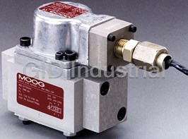
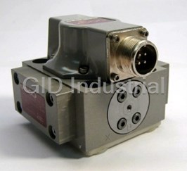
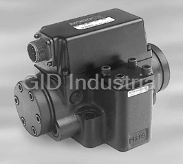
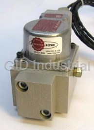
MOOG G77XK Series Electrohydraulic Servovalve Intrinsic Safety Protected
Part Number
G77XK
Price
Request Quote
Manufacturer
MOOG
Lead Time
Request Quote
Category
TBD
Datasheet
MOOG-G77XK-Series-Electrohydraulic-Servovalve-Intrinsic-Safety-Protected-datasheet1-842659000.pdf
1752 KiB

Extracted Text
G77XK Series Installation and 1. INTRODUCTION Operation Instruction This manual provides instructions and procedures necessary to install, operate and troubleshoot the Moog Inc. Series G771K/G772K/G773K Electrohydraulic Servovalve (simplified as G77XK) intrinsic safety protected industrial servovalve. It is also applicable to Moog Series 77X servovalves. Intrinsic Safety Protected The G77XK series valves are electrical equipment for hazardous areas requiring intrinsic safety or non-incendive protection. The approved hazardous location markings include: II 1 G Ex ia IIB/IIC T4 Ga KEMA 02ATEX 1015 X II 3 G Ex nA IIC T4 Gc KEMA 02ATEX 1016 X 0344 per ATEX directive 94/9/EC Ex ia IIB/IIC T4 Ga IECEx KEM 10.0041X Ex nA IIC T4 Gc IECEx KEM 10.0041X per IECEx certification scheme. The G77XK servovalves are also approved by FM, CSA, and TIIS for hazardous locations. They are intended for directional, position, velocity, pressure and force control in hydraulic control systems. Their standard fluorocarbon seals provide compatibility with a wide variety of hydraulic fluids. 2. OPERATION The Moog G77XK series industrial servovalve consists of a polarized electrical torque motor and two stages of hydraulic power amplification. The motor armature extends into the air gaps of the magnetic flux circuit and is supported in this position by a flexure tube member. The flexure tube acts as a ELECTROHYDRAULIC VALVE CUT-AWAY seal between the electromagnetic and hydraulic sections of the valve. The two motor coils surround the armature, one on each side of the flexure tube. Magnet Upper Polepiece The flapper of the first stage hydraulic amplifier is rigidly attached to the (not shown) Flexure Sleeve midpoint of the armature. The flapper extends through the flexure tube and passes between two nozzles, creating two variable orifices between the nozzle Lower Polepiece Coil tips and the flapper. The pressure controlled by the flapper and nozzle variable Flapper Armature orifice is fed to the end areas of the second stage spool. Feedback Wire Nozzle The second stage is a conventional four-way spool design in which output Spool flow from the valve, at a fixed valve pressure drop, is proportional to spool displacement from the null position. A cantilever feedback spring is fixed to the Filter flapper and engages a slot at the center of the spool. Displacement of the spool deflects the feedback spring which creates a force on the armature/flapper assembly. P B T A P B T A Inlet Orifice CAUTION Figure 1 Moog Series G77XK DISASSEMBLY, MAINTENANCE, OR REPAIR OTHER THAN IN ACCORDANCE WITH THE INSTRUCTIONS HEREIN OR OTHER SPECIFIC WRITTEN DIRECTIONS FROM MOOG WILL INVALIDATE MOOG’S OBLIGATIONS UNDER ITS WARRANTY AND YIELD THE INTRINSICALLY SAFE PROTECTION PERMIT NULL AND VOID. Input signal induces a magnetic charge in the armature and causes a 5. HYDRAULIC SYSTEM PREPARATION deflection of the armature and flapper. This assembly pivots about the flexure To prolong servovalve operational life and to reduce hydraulic system tube and increases the size of one nozzle orifice and decreases the size of the maintenance, it is recommended that the hydraulic fluid be kept at a cleanliness other. level of ISO DIS 4406 Code 16/13 maximum, 14/11 recommended. The most This action creates a differential pressure from one end of the spool to effective filtration scheme incorporates the use of a kidney loop or “off-line” the other and results in spool displacement. The spool displacement transmits a filtration as one of the major filtration components. The filter for the “off-line” force to the feedback wire which opposes the original input signal torque. Spool filtration scheme should be a ß≥75 filter for maximum effectiveness. 3 movement continues until the feedback wire force equals the input signal force. Upon system startup and prior to mounting the servovalve, the entire hydraulic system should be purged of built-in contaminating particles by an adequate flushing. The servovalve should be replaced by a flushing manifold and 3. ELECTRICAL INFORMATION AND INTRINSICALLY SAFE the hydraulic circuit powered up under conditions of fluid temperature and fluid CIRCUIT SAFETY PARAMETERS velocity, reasonably simulating normal operating conditions. New system filters a. A wide choice of coils is available for a variety of rated current are installed during the flushing process whenever the pressure drop across the requirements. The torque motor coil leads are attached to the connector filter element becomes excessive. The flushing processes should turn over the so external connections can provide series, parallel or single coil operation. fluid in the reservoir between fifty to one hundred times. The valves are equipped either with an MS type connector or with pigtail To maintain a clean hydraulic system, the filters must be replaced on leads for electrical wiring. Refer to installation drawings of the specific a periodic basis. It is best to monitor the pressure drop across the filter model for details. Servovalve coils should be driven with current to assembly and replace the filter element when the pressure drop becomes provide consistency throughout the temperature range. excessive. In addition to other filters that are installed in the hydraulic circuit, it is recommended that a large capacity, low pressure ß≥75 filter be installed b. The G77XK valves are approved for intrinsically safe protection per EN 3 in the return line. This filter will increase the interval between filter element 60079-11 and IEC 60079-11. The approved safety parameters are listed in replacements and greatly reduce the system contamination level. the following table for all the coils used by G77XK series. Coil number is marked on the valve nameplate. 6. INSTALLATION Coil Configuration EX Marking U (MAX) I (MAX) The Moog G77XK Series Industrial Servovalve may be mounted in any i i position, provided the servovalve pressure, piston and return ports match G4220-031 (single, series, parallel) Ex ia IIB T4 12 V 120 mA respective manifold ports. G4220-051/098 (single, series, parallel) Ex ia IIB T4 12 V 240 mA The mounting pattern, port location and mounting bolts of the servovalve G4221-001 G4220-042 (single) Ex ia IIC T4 16 V 160 mA are shown on Figure 4. Apply a light film of oil to the screw threads and G4221-001 G4220-042 (single) Ex ia IIC T4 24.4 V 85 mA torque to 57 inch-pounds. G4220-031 (single, parallel) Ex ia IIC T4 30 V 26 mA Wire mating connector for desired coil configuration and polarity. Thread G4220-031 (series) Ex ia IIC T4 30 V 18 mA connector to valve. G4220-051/098 (single, parallel) Ex ia IIC T4 30 V 19 mA G4220-051/098 (series) Ex ia IIC T4 30 V 12.7 mA 7. MECHANICAL NULL ADJUSTMENT It is often desirable to adjust the flow null of a servovalve independent of other system parameters. The “mechanical null adjustment” on the Moog c. The G77XK valves are approved for non-incendive operation for supply G77XK Series servovalve allows at least ±20% adjustment of flow null. The current not to exceed 50 mA dc. “mechanical null adjustor” is an eccentric bushing retainer pin located above the port designation on the valve body (see Figure 2) which, when rotated, provides d. When making electric connections to the valve, appropriate measures must control of the bushing position. Mechanical feedback elements position the be taken to ensure that locally different earth potential do not result in spool relative to the valve body for a given input signal. Therefore, a movement excessive ground currents. When barriers are required for the hazardous of the bushing relative to the body changes the flow null. location, hazardous area (field) wiring must meet the requirements of the barrier manufacturer. All barriers must be mounted and installed in compliance with the barrier manufacturer’s requirements. Twisted pairs of 18-20 gage wire are recommended. If shielded wire is used, connect shield wire to earth ground only at the barrier strip. 4. SPECIAL CONDITIONS FOR SAFE USE Because the enclosure of the apparatus is made of aluminum, if it is Figure 2 mounted in an area where the use of category 1 G apparatus is required, it Mechanical Null Adjustment must be installed such that even in the event of rare incidents, ignition sources due to impact and friction sparks are excluded. When the electrohydraulic servovalve is used in an application for type of explosion protection intrinsic safety “i”, the appropriate box on the data label Adjustment Procedure 3 must be scored. When the electrohydraulic servovalve is used in an application Using a /8 inch offset box wrench, loosen the self-locking fitting until the 1 for type of explosion protection “n”, the appropriate box on the data label null adjustor pin can be rotated. (This should usually be less than /2 turn). must be scored. DO NOT remove self-locking fitting. 3 3 After use in an application for type of explosion protection “n”, the Insert a /32 inch allen wrench in null adjustor pin. Use the /32 inch servovalve cannot abe safely used in a intrinsically safe application. Allen wrench to rotate the mechanical null adjustor pin to obtain desired The screwed cable connector may only be disconnected when the circuit flow null. Torque self-locking fitting to 57 inch lbs. is de-energized or when the location is known to be non-hazardous. When used at an ambient temperature ≥70°C, heat resistant cable must Note: be used with a continuous operating temperature in accordance with the Clockwise rotation of null adjustor pin produces flow from port P to port B. application. 8. GENERAL SERVICING RECOMMENDATIONS a. Disconnect electrical lead to servovalve. b. Relieve hydraulic system of residual pressure. c. Remove servovalve. 9. TROUBLESHOOTING CHART The following troubleshooting chart list potential troubles encountered, probable causes, and remedies. Potential Trouble Remedy Probable Cause Servovalve does not follow input command Replace filter element. signal. (Actuator or components are Plugged inlet filter element. stationary or creeping slowly.) High threshold. (Jerky, possible oscillatory Replace filter element. or “hunting” motion in closed loop Plugged filter element. system.) Replace filter element and check for dirty Poor response. (Servovalve output lags hydraulic fluid in system. Partially plugged filter element. electrical command signal). 1. Readjust null High Null Bias. (High input current 2. Replace filter element and check for 1. Incorrect null adjustment required to maintain hydraulic cylinder or dirty hydraulic fluid in system. 2. Partially plugged filter element. motor stationary.) Table 1. Replacement Parts Figure 3 End cap Part Description Qty. Part Number G77XK Series Filter Replacement Kit 1 B52555RK054K001 Inlet Orifice O-Rings (1) 2 -42082-001 Inlet Orifice O-Rings (1) 2 -42082-189 End Cap O-Rings (1) 2 -42082-042 Filter Tube (1) 1 C39486-005-060 End Cap O-Rings (1) 2 -42082-001 Filter Base O-Rings G771K 4 -42082-007 End Cap O-Rings G772K 4 -42082-013 Inlet Orifice O-Rings (two at each end cap) G773K 4 -42082-022 (1) Included in Filter Replacement Kit. 10. FILTER ASSEMBLY REPLACEMENT 11. FUNCTIONAL CHECKOUT AND CENTERING a. Install servovalve on hydraulic system or test fixture, but do not connect Tools and Equipment electrical lead. a. Blade screwdriver 3 b. Apply required system pressure to servovalve and visually examine for 16 b. / Allen wrench evidence of external leakage. If leakage is present and cannot be rectified c. Torque wrench by replacing o-rings, remove the discrepant component and return for d. Tweezers repair or replacement. 3 16 a. Remove four socket head cap screws and lockwashers using a / inch Note: If the system components are drifting or hardover, adjust Allen wrench. Remove end caps. the mechanical null of the servovalve. b. Remove o-rings from end caps. c. Connect electrical lead to servovalve and check phasing in accordance c. Remove inlet orifice assembly from both sides of body. with system requirements. Note: 2-56 screw threads into the inlet orifice assembly. Remove filter. The inlet orifice assemblies are matched to each other and 12. AUTHORIZED REPAIR FACILITIES are therefore interchangeable. If servovalve continues to malfunction after all recommended corrective Note: These assemblies seat in body and cannot go through bore action procedures are performed, defective valve should be returned to during removal. Moog for repair. Moog does not authorize any facilities other than Moog or d. Remove o-rings from inlet orifice assemblies. Moog subsidiaries to repair its servovalves. It is recommended you contact e. Visually inspect orifice assemblies for damage or foreign material. Moog at (716) 652-2000 to locate your closest Moog repair facility. Repair by f. Discard o-rings and filter. an independent (unauthorized) repair house will result in voiding the Moog g. Install o-rings on inlet orifices. warranty and could lead to performance degradation or safety problems. h. Install filter and inlet orifice assembly in body. Inlet orifice assembly pilots into filter. Install the other inlet orifice assembly into other end of filter. i. Install o-rings on end caps. 13. DECLARATION OF MANUFACTURER j. Install end caps on body and install four socket head cap screws and An EC Declaration of Conformity according to Council Directive 94/9/ lockwashers. Torque the screws to 85 inch-pounds. EC is supplied with each servovalve. 1.88 1.88 47.8 47.8 4X Ø.221(5.61) THRU (G771 AND G772) .014 G77XK SERIES INSTALLATION AND OPERATION INSTRUCTION NOTES OR 2.550 4X Ø.265(6.73) THRU (G773) 64.77 .007 1.12 MAX 1 Fluid: 1.275 [28.4] 1.88 1.88 32.39 (OPTION) Industrial type petroleum base hydraulic 47.8 47.8 4X Ø.221(5.61) THRU (G771 AND G772) fluid, maintained to ISO DIS 4406 Code .014 1.39 MAX OR 1.06 2.550 35.3 14/11 recommended. 26.9 4X Ø.265(6.73) THRU (G773) 64.77 1.343 .007 1.12 MAX 34.11 1.275 1.00 [28.4] 2 Operating Temperature Range: 25.4 32.39 (OPTION) -20°F [-29°C] to +275°F [+135°C] unless .671 17.04 1.39 MAX .844 otherwise specified on nameplate. 1.06 35.3 21.44 26.9 1.688 1.343 3 Valve Phasing: 42.88 34.11 1.00 25.4 Flow out port B results when Series ELECTRICAL CONNECTOR coils: B & C connected, A+, D-; .671 2.12 PIN D PIN A 17.04 53.8 .844 Parallel coils: A & C connected, B & D 21.44 PIN C PIN B connected; Single coil: A+, B-, or C+, D-. 1.688 42.88 4 Ports: 2.81 ELECTRICAL CONNECTOR 2.18 71.4 1.75 See table below left. 55.4 1.56 2.12 44.5 1.03 PIN D PIN A 39.6 53.8 MTG HGT 26.2 P 5 Surface: PIN C PIN B Surface to which valve is mounted LOCATING PIN .12 MAX 3.0 32 EXTERNAL NULL ADJUST requires [ ] finish, flat within 0.002 Ø.062 2.81 3/32 IN. HEX SOCKET 1.57 2.18 71.4 [0.05] TIR. 1.75 1.56 55.4 44.5 1.03 39.6 MTG HGT 26.2 6 Null Adjust: P Flow out port B results with clockwise LOCATING PIN .12 MAX 3 rotation of null adjust screw ( /32 hex 3.0 EXTERNAL NULL ADJUST Ø.062 key). Flow bias is continually varied for a 3/32 IN. HEX SOCKET 1.57 X given port as the null adjust is rotated. 6 F1 F2 G TYPICAL WIRING SCHEMATIC P A B Y X T T F2 F3 F1 F4 G A B C D P G771K U.S. METRIC Y A B 3 P A B T G F1 F2 F3 F4 P A B T G F1 F2 F3 F4 4.85 4.85 4.85 4.85 2.39 M5 M5 M5 M5 Ø .191 Ø .191 Ø .191 Ø .191 Ø .094 .190-32 .190-32 .190-32 .190-32 T T X 0.84 0.53 1.16 0.84 0.45 0 1.69 1.69 0 X 21.3 13.5 29.5 21.3 11.4 0 42.9 42.9 0 F4 F3 Y 9.1 17.0 17.0 24.9 4.3 0 0 34.0 34.0 Y 0.36 0.67 0.67 0.98 0.17 0 0 1.34 1.34 G772K U.S. METRIC P A B T G F1 F2 F3 F4 P A B T G F1 F2 F3 F4 Ø .260 Ø .260 Ø .260 Ø .260 Ø .094 .190-32 .190-32 .190-32 .190-32 6.6 6.6 6.6 6.6 2.39 M5 M5 M5 M5 X 21.3 11.4 31.2 21.3 11.4 0 42.9 42.9 0 X 0.84 0.45 1.23 0.84 0.45 0 1.69 1.69 0 Y 0.28 0.67 0.67 1.06 0.17 0 0 1.34 1.34 Y 7.2 17.0 17.0 27.0 4.3 0 0 34.0 34.0 G773K U.S. METRIC P A B T G F1 F2 F3 F4 P A B T G F1 F2 F3 F4 Ø .312 Ø .312 Ø .312 Ø .312 Ø .094 .250-20 .250-20 .250-20 .250-20 7.92 7.92 7.92 7.92 2.39 M6 M6 M6 M6 X 0.84 0.38 1.31 0.84 0.45 0 1.69 1.69 0 X 21.3 9.7 33.3 21.3 11.4 0 42.9 42.9 0 Y 0.20 0.67 0.67 1.14 0.17 0 0 1.34 1.34 Y 5.1 17.0 17.0 29.0 4.3 0 0 34.0 34.0 Figure 4 4 Three standard designs are available. Port Circle Port Model Diameter Diameter Manifold O-Rings Mounting Bolt Size Number in mm in mm Moog MS (socket head cap screws) G771K .625 15.8 .191 4.85 -007 -010 .190-32 NF G772K .780 19.8 .260 6.60 -013 -012 .190-32 NF G773K .937 23.8 .312 7.93 -022 -013 .250-28 NF Moog Inc., East Aurora, NY 14052-0018 The products described herein are subject to change at any time without notice, including, but not limited to, product features, specifications, and designs. Telephone: 716/652-2000 Fax: 716/687-7910 Toll Free: 1-800-272-MOOG www.moog.com/industrial CDS6768 RevC 500-427 0112 ∆∆
Frequently asked questions
What makes Elite.Parts unique?

What kind of warranty will the G77XK have?
Which carriers does Elite.Parts work with?
Will Elite.Parts sell to me even though I live outside the USA?
I have a preferred payment method. Will Elite.Parts accept it?


What they say about us
FANTASTIC RESOURCE
One of our top priorities is maintaining our business with precision, and we are constantly looking for affiliates that can help us achieve our goal. With the aid of GID Industrial, our obsolete product management has never been more efficient. They have been a great resource to our company, and have quickly become a go-to supplier on our list!
Bucher Emhart Glass
EXCELLENT SERVICE
With our strict fundamentals and high expectations, we were surprised when we came across GID Industrial and their competitive pricing. When we approached them with our issue, they were incredibly confident in being able to provide us with a seamless solution at the best price for us. GID Industrial quickly understood our needs and provided us with excellent service, as well as fully tested product to ensure what we received would be the right fit for our company.
Fuji
HARD TO FIND A BETTER PROVIDER
Our company provides services to aid in the manufacture of technological products, such as semiconductors and flat panel displays, and often searching for distributors of obsolete product we require can waste time and money. Finding GID Industrial proved to be a great asset to our company, with cost effective solutions and superior knowledge on all of their materials, it’d be hard to find a better provider of obsolete or hard to find products.
Applied Materials
CONSISTENTLY DELIVERS QUALITY SOLUTIONS
Over the years, the equipment used in our company becomes discontinued, but they’re still of great use to us and our customers. Once these products are no longer available through the manufacturer, finding a reliable, quick supplier is a necessity, and luckily for us, GID Industrial has provided the most trustworthy, quality solutions to our obsolete component needs.
Nidec Vamco
TERRIFIC RESOURCE
This company has been a terrific help to us (I work for Trican Well Service) in sourcing the Micron Ram Memory we needed for our Siemens computers. Great service! And great pricing! I know when the product is shipping and when it will arrive, all the way through the ordering process.
Trican Well Service
GO TO SOURCE
When I can't find an obsolete part, I first call GID and they'll come up with my parts every time. Great customer service and follow up as well. Scott emails me from time to time to touch base and see if we're having trouble finding something.....which is often with our 25 yr old equipment.
ConAgra Foods