

 Manufacturers
LENZE AC TECH EVS9325ES

Description
Lenze AC Tech's EVS9325-ES Servo Controller offers flexibility. The inverters are
equipped for all the different requirements of servo technology, so that you can
choose among the suitable technique according to your application. An integrated
mains input, regenerative power supply modules, and feedback systems.
Part Number
EVS9325ES
Price
Request Quote
Manufacturer
LENZE AC TECH
Lead Time
Request Quote
Category
PRODUCTS - E
Datasheet

Extracted Text
454 202 Lenze Global Drive 9300 servo inverters Lenze Drive Systems GmbH, Postfach 1013 52, D-31763 Hameln, Site: Groß Berkel Hans-Lenze-Straße 1, D-31855 Aerzen, Phone ++49 (0) 5154 82-0, Telefax ++49 (0) 5154 82-21 11 E-Mail : Lenze@Lenze.de · Internet : http://www.Lenze.com Technical alterations reserved · Printed in Germany 07.02 by ME / LHM · 98/09 en Select and order This catalog helps you to easily select and order your This catalog includes: desired servo drive. • Servo inverters for the control of servo motors • Different servo inverter versions • Accessories for mounting and wiring of inverters • Application examples • Order forms 9300 Automation Communication to host System bus components Terminal expansion Hand terminal PC/system bus converter BCD decade switch Operation terminal 2 Lenze 9300 servo drive system overview Mains Mains fuses or automatic circuit breakers EFS series... Mains filter A Mains filter B Type EZN3A... EZN3B... Operation module EMZ9371BB Brake chopper ERB... Automation module EMF2xxxIB Servo inverter EVS93XX-E Brake chopper EMB9352-E Introducing Lenze Intelligent drives for automation. Intelligence is a built-in feature of the Lenze Global Drive Due to their controller structure - that can be freely controllers. When used in any machine, this is a interconnected internally - the servo inverters, servo register considerable cost benefit for the design engineer. controllers, 9300 servo positioning controllers cut down on the need for external peripherals. For Starting with the 8200 Global Drive frequency inverters in example, the 9300 servo positioning contoller includes series production or HVAC and pump technology, complete positioning control features via software functions. frequently used automation functionality (e. g. PID Every device version contains technology functions that controllers) has been integrated into the device. can, for example, execute subprocesses. Additional control elements of the system can be evaluated by means of control inputs and outputs as well as via the system bus. Intelligent drives have a name: Global Drive. freely connectable function blocks preconfigured technology functions operating system servo controller List of abbreviations Abbreviations used in this catalog Controllers General V [V] Mains voltage 93xxE 9321 to 9332E types Mains I [A] Mains current 934xE 9341 to 9343E types Mains V [V] DC bus voltage 935xE 9351 to 9352E types G I [A] Rated current / Output current r I [A] Maximum output current AC AC current/voltage max DC DC current/voltage P [kW] Rated motor power r S [kVA] Inverter output power DIN Deutsches Institut für Normung r P [W] Inverter power loss (German Standardization Authority) loss f [kHz] Chopping frequency EMC Electromagnetic Compatibility ch f [Hz] Set maximum frequency max f [Hz] Field frequency EN Europäische Norm (European Standard) d L [mH] Inductance IEC International Electrotechnical R [?] Resistance Commission IP International Protection Code NEMA National Electrical Manufacturers Association VDE Verband deutscher Elektrotechniker Association of German Electrical Engineers CE Communauté Européene IM International Mounting Code 6 Lenze Contents Operation module Product information 9371 Operation module _________________________ 51 Survey_____________________________________________9 Other accessories Integrated technologies_____________________________10 System bus components ________________________ 52 Inverters for your applications _______________________11 Digital display / Setpoint potentiometer ____________ 54 General 9300 product information ___________________12 Communication via host Networking using RS 232/485____________________ 56 High-speed networking Order information via host________________________________________ 56 Drive selection step-by-step _______________________ 15 Survey of the accessories Drive selection ____________________________________16 Accessories for 9300 servo inverters ______________ 57 Assigned accessories for 9321-9328 servo inverters ____________________ 58 Assigned accessories 93xx selection for 9329-9332 servo inverters ____________________ 59 Assigned accessories Features_________________________________________ 18 for regenerative power supply modules ___________ 59 General data _____________________________________ 20 System cables Technical data 9321-9325 _________________________ 21 General________________________________________ 61 Technical data 9326-9329 _________________________ 22 Motor cable____________________________________ 62 Technical data 9330-9332 _________________________ 23 Blower cable ___________________________________ 64 Resolver- / Encoder cable________________________ 65 Mechanical installation Other system cables ____________________________ 66 General notes __________________________________ 24 Mounting with fixing rail _________________________ 25 Thermal separation _____________________________ 26 Application examples Cable protection Survey ________________________________________ 27 Connecting diagrams Cable-protecting fuses __________________________ 28 Power connection ______________________________ 67 Automatic circuit breakers _______________________ 29 Control connection _____________________________ 68 DC-bus connection _____________________________ 69 CE-typical installation General notes __________________________________ 30 Mains filter A ___________________________________ 32 Mains filter B___________________________________ 36 Order forms Braking operations ______________________________________________ 70/71 Options________________________________________ 40 9351 Brake module _____________________________ 41 9352 Brake module _____________________________ 42 Brake resistors _________________________________ 44 Lenze worldwide Regenerative power supply module ______________________________________________ 72/73 General data ___________________________________ 46 Mains filter A ___________________________________ 48 DC bus fuses __________________________________ 49 DC bus connection _____________________________ 50 Lenze 7 8 Lenze i 9300 Product information Survey 9300 servo inverters - flexible and modern automation Servo inverters of the 9300 series with a matching motor This drive concept offers automation solutions based on a and geared motor programme form a perfect drive system. consistent platform. Market-oriented intelligence enables general technology Attachable InterBus and PROFIBUS fieldbus modules are functions (electrical shaft or positioning control) as well as available for the connection to a host control system. electronic alternatives to mechanical components (register The hardware of the servo product series is uniformly control, cam profiler). equipped with the following features: Thus, costly upgrades with control cams, pull rods, and Universality - the product series is universally applicable in also clutches are not necessary in the manufacturing the power range from 0.37 to 75 kW. process. Integrated mains input - for single drive operations only These intelligent drives coordinate - accurately and one element instead of two separated elements is required. precisely - all different movements of the machines to one Regenerative power supply modules - ensure energy-saving another. No matter whether the system is equipped with a group applications and multi-axis applications. central control station or is controlled locally - high Feedback systems - ensure a perfect adaptation to the flexibility is guaranteed. machine requirements by means of resolvers or SinCos feedback. Lenze 9 i 9300 product information Integrated technologies The integrated technology function forms a vital part of the 9300 cam profiler intelligent drive solution. The 9300 servo inverter series comprise four software variants in identical hardware devi- Mechanical cams can be found quite frequently in ces: production machinery. Changing or modifying the product causes lengthy and complicated set-up procedures. - 9300 servo The 9300 servo cam profiler can store up to 8 different - 9300 register control cam profiles, so that cam profiles can be switched without - 9300 cam profiler delay during production. For a multitude of potential - 9300 positioning control applications of the cam profiler a variety of additional functions have been integrated, e. g. electronic cam All four variants are equipped with a uniform user interface. switches and marker-controlled cam start. Especially for The respective technology function can be set quickly and opening and closing of welding bars a function has been easily. In detail: integrated in order to achieve constant welding periods at variable clock frequencies. 9300 inverter 9300 positioning control This inverter implements frequently used functions of a servo drive. The electronic gearbox is an essential Positioning made deceptively simple. The 9300 positioning technology function in this device. As an alternative to the control includes a complete position controller with mechanical vertical shaft, several drives can be operated sequence control. Easy commissioning with only few input at exact synchronisation by master frequency preselection. values is a modern solution as compared with external Proportional synchronisation can be implemented easily position controllers and their complicated programming and flexibly by means of adjustable gearing. Feedback language. Responses from limit switches or other drives systems such as resolvers or SinCos encoders provide can be evaluated at the same time. If the initial position of highest precision. the product is tainted with considerable tolerances, the target position is reliably found by automatic material correction. 9300 register control There are many machines that are processing material lengths. Second printings, cuts, perforations, embossings, or splices require the material length to be positioned precisely to form the resulting print image. However, due to process-dependant fluctuations (material characteristics, production parameters) the position of the print image tends to drift. The basic prerequisite "autosyn" is added by the requirement for overlaid register alignment of the rotative motion at the print image. The register control already integrated in the servo inverter always re-aligns the angular position of draw-in rollers, printing cylinders, or other processing stations with the print image. Thus, second printings, cuts, perforations, embossings, or splices will always be at the required position. Finally, drift errors are a thing of the past. Even without host control and without overlay gearing. 10 Lenze i 9300 product information Inverters for your application This catalog lists inverters for respective applications. For the 9300 series the software loaded decides on the Functions and features of the inverters have been adapted available functionality. The following categories are available: to market requirements. Printing machines, Printing machines, Packaging machines, Packaging textile machines, paper machines, production machines, machines, packaging packaging, foil printing machines wood processing, machines processing and warehouse technology textile machines Requirement High response and Insetting, printing, Profiling, Exact position- comprehensive cutting, embossing, filling different ing and applications perforating, goods comprehensive material requirements (profile changes) applications Single-phase ---- Three-phase 9321-9332 9321-9332 9321-9332 9321-9332 servo register control cam disc positioning control Compact design �� � � Short-circuit protection �� � � Vector control �� � � Bipolar setpoint �� � � Freely assignable �� � � inputs and outputs Error signal output �� � � DC brake �� � � system slip �� � � compensation Mains failure �� � � monitoring Digital frequency input �� � � Sensorless � � speed control Relative/Absolute � positioning Homing �� � Point-to-point � positioning Register control � Teach-in for � significant web marker Time or path based generation � of correcting variable Eight selectable profiles � Cam switchgear, �� switch points Lenze 11 i 9300 product information Matched system CE conformity - Servo inverters with matched servo The servo inverters of the 9300 series naturally meet motors (asynchronous, synchronous) the EC Directives: - Regenerative power supply modules - CE conformity according to the Low-Voltage - Accessories for braking Directive - Cold Plate variants for special applications. - CE conformity according to the Directive of Electromagnetic Compatibility for a typical drive Intelligent drive controller configuration with frequency converter. Ability to execute complete processes or subprocesses through integrated technology and UL approved control functionality. The global application of these controllers is ensured by a UL approval. Easy operation UL 508 and UL-508c ensure the application in the US. The 9300 servo inverters can be parameterized using an operation module. This operation module serves as display and for diagnostics. Communicating Alternatively, you can use the Global Drive Networks to the most common fieldbus systems are Control operating software. possible: Consistency - LECOM A/B: Networking via RS232/485 Across the entire range, the controllers are interface consistent in - LECOM LI Networking via fibre optics power operation - InterBus-S: Connection to the remote bus networking. using DRIVECOM profile 21 - System bus Connection to I/O terminals as (CAN): well as several inverters to each other. - PROFIBUS: Communication via PROFIBUS-DP. 12 Lenze i 9300 product information Flexibility Energy-saving The inverters are equipped for all the different The power supply is adapted to the load so that only requirements of servo technology, i. e you can as much energy as required for the momentary choose among the suitable technique according to torque / current is consumed. your application. Space-saving Integrated mains input Thanks to their book-shelf design, the frequency For single drive operations only one element instead inverters can be installed particularly space-saving in of two separate elements is required. the control cabinet, without having to provide free space. Comprehensive mounting accessories Regenerative power supply modules allow diverse mounting positions. They ensure energy-saving group applications and multi-axis applications. Motors can be adapted The modular design of the motors and planned Feedback systems variants facilitate the right selection for the individual They ensure a perfect adaptation to the machine application: requirements. You can select among resolver, Servo motor flanges with through-holes in TTL encoder, or SinCos encoder. B5 mounting or with threaded holes in B14 mounting. Different encoders that can be integrated allow the Considerably reduced controller requirements adaptation to the required precision: because of high functionality: - Resolvers as standard solution - Digital frequency for synchronous running by - Optimum behaviour thanks to internal means of simple plug connectors improvement of the resolver accuracy - Integrated position controller for exact positioning - Incremental encoders or SinCos absolute value - Vector control for highly dynamic response encoders can also be used for special applications. and high starting torque - Modular design of freely assignable control and function blocks for easy connection - Process control and arithmetic blocks for control tasks - Integrated system for interconnection of several controllers. The most suitable setpoint source for each application: - Via setpoint potentiometer to the control terminals - Via master voltage or master current to the control terminals - Via the operation module at the frequency inverter - Via a networking module directly from a host Lenze 13 14 Lenze i 9300 order information Drive selection step-by-step The following chapters of this catalog help you to a tailor-made servo drive for your machinery. Please enter your choice in the order form. Å This section provides detailed information Example: 1. Select 93XX-E controller type • Servo drive for 11.0 kW motor (Å Selection, technical data) Select the controller and the servo motor for your drive. The controller EVS9326-E type depends on the required motor power. 2. Determine the way of installation • Control cabinet in IP41 enclosure (Å Selection, mechanical installation) Select the accessories for the installation • Heat sink is separated, therefore a smaller controller of the servo inverter. cabinet can be used Frame for thermal separation EJ0038 3. Select accessories at the mains side • Connection of the drive: (Å Selection, electrical installation at the mains side) to an industrial mains Select suitable fuses and accessories required to comply with the limit classes prescribed • RFI suppression: by the European legislation. The ambiance requires limit value class A according to EN 55011 Mains filter EZN3A0150H024 4. Select other accessories for • For analog setpoint input via master voltage the controller or master current: (Å Selection, other accessories) Select useful accessories for the Setpoint potentiometer ERPD001k0001W controller: Scale for potentiometer ERZ0002 - Operation module Knob for potentiometer ERZ0001 - Automation accessories - Setpoint potentiometer • If you want to change the factory settings - System cable in a simple and convenient way: Operation module EMZ9371BB Lenze 15 i Ordering information Drive selection step-by-step 1. Motor size and blower type Å Technical data, detailed selection in Lenze formulary • Determine maximum torque M , maximum speed n , max max effective torque M , and rms gear ratio i, if necessary Gear ratio: - for good utilization ratio - for optimum dynamic response for continuous duty n J r last load N i ≈ i ≈ J n last motor load Effective torque: 2 1 MMM = t rms ∑ eff T ii i Maximum torque: 11 MM=+ M max beschl accel last i η load getriebe gear ∆n 1 M =⋅ 2 π () JJ + ) beschl accel motor 2 last load i ∆t Select motor according to n , M > M and Example: MDFKA 080-22, 120 Hz max r rms take into consideration: Asynchronous servo motor with external blower, - No air stream allowed at process � Motor without blower MDSK 3.9 kW, 10.8 Nm, 3455 rpm - Fluff or similar material that may clog air ducts � Motor without blower MDSK - High protection rating required � Motor without blower MDSK - High dynamic response required � Motor with blower MDFK, � Synchronous servo motor MDXKS - Operation with constant power at high � Asynchronous servo motor MDXKA speeds (field weakening operation) - Very high power density � Synchronous servo motor MDXKS - Parallel operation of servo motors � Asynchronous servo motors MDXKA at one single inverter 16 Lenze i Ordering information Drive selection step-by-step 2. Selecting the encoder Encoder Resolver Single-turn SinCos encoder Multi-turn SinCos encoder available for Synchronous servo motor •• • MDXKS Asynchronous servo motor •• • MDXKA, surface-cooled Asynchronous servo motor •• • MDXKA, enclosed-ventilated Abbreviation RS AS512 AM512 Type SCS 70 SCM 70 Signals 512 periods, 512 periods, sine wave signals 1 Vpp sine wave signals 1 Vpp Resolution 0.8 � 0.4 � 0.4 � Accuracy ± 10 � resp. ± 4 � ± 0.8 � ± 0.8 � for correction code input Absolute positioning 1 turn 1 turn 4096 turns Comments Standard solution Uses SinCos encoder instead of resolver, for most actual position via 9300 interface, applications operation only possible when encoder at 9300 has been selected, (encoder type and supply voltage) values have been stored, and controller has been switched off and on Lenze 17 9300 Selection Features Compact servos and position controllers for single-phase mains connection: Servo Position controller EVS93XX-ES EVS93XX-EP 0.37-75.0 kW 0.37-75.0 kW Single axis in narrow design �� Heatsink can be separated �� Power connection at the top �� Motor connection at the bottom �� Direct connection of resolver and encoder, TTL or SinCos �� Phase controller can be integrated �� Motor-phase monitoring for asynchronous motor �� Mains failure monitoring �� Field-oriented control �� Sensorless speed control (SSC technology) �� Digital synchronization system via digital frequency �� Integrated digital-frequency input and output �� User configuration �� Modular function blocks �� Process controller and arithmetic blocks �� Integrated system bus interface (CAN) �� UL approval, file no. 132659 (listed) �� Point-to-point positioning with/without overshooting � Easy programming via 32 program sets (PS) and variable tables (VT) � Relative / absolute positioning � Direct evaluation of a SinCos absolute value encoder �� Switch the outputs, query the inputs � Set reference and actual position value � Initiate program branches depending on digital input � Initiate program branches depending on piece counter � Touch-probe positioning � Manual positioning � Switching points � Switching points dynamically adjustable � 2 sin ramps � Acceptance of new drive profile parameters during ongoing positioning procedure � Override (speed and acceleration) � Hand teach-in � Arithmetic linking of target positions � Manual positioning with intermediate stop � PFB actual position actual value storage by touch-probe � Freely assignable input variables for analog, binary, and BCD values � Standby operation, switch-over from positioning to phase-synchronous running � Can-bus synchronization of the position controller � Various function blocks for long value arithmetic and � signal type conversion Attachable accessories Operation module 9371BB for parameterization and parameter transfer �� Serial RS232/485 module via wire or 2102IB fibre optics �� 2111IB InterBus-S module �� 2131IB PROFIBUS module �� 18 Lenze 9300 Selection Features Compact register controllers and cam profilers for three-phase mains connection: Register Cam controller profiler EVS93XX-ER EVS93XX-EK 0.37-75.0 kW 0.37-75.0 kW Single axis in narrow design �� Heatsink can be separated �� Power connection at the top �� Motor connection at the bottom �� Direct connection of resolver and encoder, TTL or SinCos �� Phase controller can be integrated �� Motor-phase monitoring for asynchronous motor �� Mains failure monitoring �� Field-oriented control �� Sensorless speed control (SSC technology) �� Digital synchronization system via digital frequency �� Integrated digital-frequency input and output �� User configuration �� Modular function blocks �� Process controller and arithmetic blocks �� Integrated system bus interface (CAN) �� UL approval, file no. 132659 (listed) �� Direct evaluation of SinCos absolute value encoders �� Register correction during running � Integrated servo controller for gear ratio compensation � Teach-in function for determination of significant web mark � Adjustable window for marker detection � Mark sensor monitoring � Dead time compensation of sensor system � Adaptable controller characteristics � Preselection of product data in mm or inch (time- and path-dependant) � Variable correction variable limiting � Eight profiles stored in the controller � Integrated cam switch � Throw-in / throw-out � Stretching / compression of cam � Offset in x and y direction � Virtual master � Welding bar control � Cam profile start by external signal � Attachable accessories Operation module 9371BB for parameterization and parameter transfer �� Serial RS232/485 module via wire or 2102IB fibre optics �� 2111IB InterBus-S module �� 2131IB PROFIBUS module �� Lenze 19 9300 Selection General data Range Values Vibration resistance Germanischer Lloyd, general conditions Humidity Humidity class F without condensation (average relative humidity 85 %) Permissible temperature ranges during transport of the controller: -25 °C ... +70 °C during storage of the controller: -25 °C ... +55 °C during operation of the controller: 0 °C ... +40 °C +40 °C ... +50 °C with power derating 2.5 % per K Permissible installation height h up to 1000m a.m.s.l. without power derating 1000 m a.m.s.l. ... 4000 m a.m.s.l. 5 % / 1000 m Degree of pollution VDE 0110 part 2 pollution degree 2 Noise emission Requirements to EN 50081-1, EN 50081-2, IEC 22G-WG4 (Cv) 21 Limit value class A to EN 55011 (industrial area) with mains filter Limit value class B to EN 55022 (residential area) with mains filter and installation into control cabinet Noise immunity Limit values maintained using mains filter. Requirements to EN 50082-2, IEC 22G-WG4 (Cv) 21. Requirements Standard Severity levels ESD EN61000-4-2 3, d. h. 8 kV for air discharge and 6 kV for contact discharge RF interference (enclosure) EN61000-4-3 3, i. e. 10 V/m; 27 to 1000 MHz Burst EN61000-4-4 3/4, i. e. 2 kV/5 kHz Surge (on mains cable) IEC 1000-4-5 3, i. e. 1.2/50 ms 1 kV phase-to-phase, 2 kV Phase-PE Dielectric strength Surge strength class III according to VDE 0110 Packaging according to DIN 4180 - 9321 to 9326: packaging for protection against dust - 9327 to 9332: packaging ready for dispatch Type of protection IP20 IP41 on the heatsink side for thermal separation in push-through technique NEMA 1: Protection against contact Approvals CE: Low-Voltage Directive UL 508: Industrial Control Equipment UL 508C: Power Conversion Equipment 20 Lenze � � 9300 Selection Ratings Type 9321 9322 9323 9324 9325 Servo order No. EVS9321-ES EVS9322-ES EVS9323-ES EVS9324-ES EVS9325-ES Register control order No. EVS9321-ER EVS9322-ER EVS9323-ER EVS9324-ER EVS9325-ER Cam disc order No. EVS9321-EK EVS9322-EK EVS9323-EK EVS9324-EK EVS9325-EK Position controller order No. EVS9321-EP EVS9322-EP EVS9323-EP EVS9324-EP EVS9325-EP Mains voltage V [V] 320 V ... 528 V ± 0 % ; 45 Hz ... 65 Hz ± 0% r Alternative DC supply VG [V] 460 V ... 740 V +/-0% Ratings for operation at a mains: 3 AC / 400 V / 50 Hz / 60 Hz Motor power (4-pole ASM) P [kW] 0.37 0.75 1.5 3.0 5.5 r 1) 1) 1) 1) Output current (8 kHz) I [A] 1.5 / 1.05 2.5 / 1.7 3.9 / 2.6 7.0 / 4.7 13.0 r8 1) 1) 1) 1) Output current (16 kHz) I [A] 1.1 / 0.77 1.8 / 1.26 2.9 / 2.03 5.2 / 3.64 9.7 r16 Output power S [kVA] 1.0 1.7 2.7 4.8 9.0 r8 Ratings for operation at a mains: 3 AC / 480 V / 50 Hz / 60 Hz Motor power (4-pole ASM) P [kW] 0.37 0.75 1.5 3.0 5.5 r 1) 1) 1) 1) Output current (8 kHz) I [A] 1.5 / 1.05 2.5 / 1.7 3.9 / 2.6 7.0 / 4.7 13.0 r8 1) 1) 1) 1) Output current (16 kHz) I [A] 1.1 / 0.77 1.8 / 1.26 2.9 / 2.03 5.2 / 3.64 9.7 r16 Output power S [kVA] 1.2 2.1 3.2 5.8 10.8 r8 1) 1) 1) 1) Max. output current at 8 kHz I 2.3 / 3.0 3.8 / 5.0 5.9 / 7.8 10.5 / 14 19.5 max 1) 1) 1) 1) Max. output current at 16 kHz I 1.65 / 2.2 2.7 / 3.6 4.4 / 5.8 7.8 / 10.4 14.6 max Mains current at V 400 V I [A] 1.5 2.5 3.9 7.0 12.0 mains r Motor voltage V [V] 3 ~ 0 ... V M mains Power loss at V 400 V P [W] 100 110 140 200 260 mains loss Power derating [%/K] 40 °C < T < 50 °C: 2%/K amb [%/m] 1000 m a.m.s.l. ... 4000 m a.m.s.l.: 5 % / 1000m Dimensions [mm] a 78 x 78 x 97 x 97 x 135 x b 350 x 350 x 350 x 350 x 350 x e 250 x 250 x 250 x 250 x 250 x Weight m [kg] 3.5 3.5 5.0 5.0 7.5 1) Acceleration drive operating mode � b � e a Lenze 21 � � � � 9300 Selection Ratings Type 9326 9327 9328 9329 Servo order No. EVS9326-ES EVS9327-ES EVS9328-ES EVS9329-ES Register control order No. EVS9326-ER EVS9327-ER EVS9328-ER EVS9329-ER Cam disc order No. EVS9326-EK EVS9327-EK EVS9328-EK EVS9329-EK Position controller order No. EVS9326-EP EVS9327-EP EVS9328-EP EVS9329-EP Mains voltage V [V] 320 V ... 528 V ± 0 % ; 45 Hz ... 65 Hz ± 0% r Alternative DC supply VG [V] 460 V ... 740 V +/-0% Ratings for operation at a mains: 3 AC / 400 V / 50 Hz / 60 Hz Motor power (4-pole ASM) P [kW] 11.0 15.0 22.0 30.0 r Output current at 8 kHz I [A] 23.5 32.0 47.0 59.0 r8 Output current at 16 kHz I [A] 15.3 20.8 30.6 38.0 r16 Output power S [kVA] 16.3 22.2 32.6 40.9 r Ratings for operation at a mains: 3 AC / 480 V / 50 Hz / 60 Hz Motor power (4-pole ASM) P [kW] 11.0 18.5 30.0 37.0 r Output current at 8 kHz I [A] 22.3 30.4 44.7 56.0 r8 Output current at 16 kHz I [A] 14.5 19.2 28.2 35.0 r16 Output power S [kVA] 18.5 25.0 37.0 46.6 r Max. output current at 8 kHz I 35.3 48.0 70.5 88.5 max Max. output current at 16 kHz I 22.9 31.2 45.9 57 max Mains current at V 400 V I [A] 20.5 27.0 44.0 53.0 mains r Motor voltage V [V] 3 ~ 0 ... V M mains Power loss at V 400 V P [W] 360 430 640 810 mains loss Power derating [%/K] 40 °C < T < 50 °C: 2%/K amb [%/m] 1000 m a.m.s.l. ... 4000 m a.m.s.l.: 5 % / 1000m Dimensions [mm] a 135 x 250 x 250 x 250 x b 350 x 350 x 350 x 350 x e 250 250 250 250 Weight m [kg] 7.5 12.5 12.5 12.5 � b � e a 22 Lenze � � � � 9300 Selection Ratings Type 9330 9331 9332 Servo order No. EVS9330-ES EVS9331-ES EVS9332-ES Register control order No. EVS9330-ER EVS9331-ER EVS9332-ER Cam disc order No. EVS9330-EK EVS9331-EK EVS9332-EK Position controller order No. EVS9330-EP EVS9331-EP EVS9332-EP Mains voltage V [V] 320 V ... 528 V ± 0 % ; 45 Hz ... 65 Hz ± 0% r Alternative DC supply VG [V] 460 V ... 740 V +/-0% Ratings for operation at a mains: 3 AC / 400 V / 50 Hz / 60 Hz Motor power (4-pole ASM) P [kW] 45.0 55.0 75.0 r Output current at 8 kHz I [A] 89.0 110.0 145.0 r8 Output current at 16 kHz I [A] 58.0 70.0 90.0 r16 Output power S [kVA] 51.5 76.2 100.9 r Ratings for operation at a mains: 3 AC / 480 V / 50 Hz / 60 Hz Motor power (4-pole ASM) P [kW] 45.0 55.0 90.0 r Output current at 8 kHz I [A] 84.0 105.0 125.0 r8 Output current at 16 kHz I [A] 55.0 65.0 80.0 r16 Output power S [kVA] 69.8 87.8 104.0 r Max. output current at 8 kHz I 133.5 165.0 225.0 max Max. output current at 16 kHz I 87 105 135 max Mains current at V 400 V I [A] 78.0 96.4 129.1 mains r Motor voltage V [V] 3 ~ 0 ... V M mains Power loss at V 400 V P [W] 1100 1470 1960 mains loss Power derating [%/K] 40 °C < T T < 50 °C: 2%/K amb [%/m] 1000 m a.m.s.l. ... 4000 m a.m.s.l.: 5 % / 1000m Dimensions [mm] a 340 x 440 x 440 x b 591 x 680 x 680 x e 285 285 285 Weight m [kg] 36.5 59.0 59.0 � b � e a Lenze 23 � � 9300 Selection Mechanical installation of 9300 servos General notes The servo inverters of the 9300 series can be installed in a control cabinet as follows: - Inverters must only be used as built-in units! - If the exhaust air contains pollutants (dust, fluff, Using the mounting rails included or grease, aggressive gases) ensure sufficient measures using thermal separation (e.g. installation of filters, periodic cleaning, etc.) - Ensure free spaces When installing several inverters in one control cabinet they can be fixed side by side. Ensure unimpeded air circulation. Ensure a free space of 100 mm at top and bottom - In the event of continuous vibrations or shocks: Check the application of shock absorbers. 24 Lenze 9300 Selection Installation with fixing rail The controllers are supplied with a fixing rail which can be Alternatively, thermal separation is possible. used to mount the servo inverter onto the rear panel of a control cabinet or onto a mounting plate. The mounting rail is fixed in a rail at the controller so that fixing brackets are available at top and bottom. e1 e a b b1 c c1 d d1 e e1 g k m Controller [mm] [mm] [mm] [mm] [mm] [mm] [mm] [mm] [mm] [mm] [mm] [mm] 9321 78 384 350 39 - 365 - 250 230 6.5 30 - 9322 78 384 350 39 - 365 - 250 230 6.5 30 - 9323 97 384 350 48.5 - 365 - 250 230 6.5 30 - 9324 97 384 350 48.5 - 365 - 250 230 6.5 30 - 9325 135 384 350 21.5 92 365 - 250 230 6.5 30 - 9326 135 384 350 21.5 92 365 - 250 230 6.5 30 - 9327 250 402 350 22 206 370 23.5 250 230 6.5 24 11.0 9328 250 402 350 22 206 370 23.5 250 230 6.5 24 11.0 9329 250 402 350 22 206 370 23.5 250 230 6.5 24 11.0 9330 340 672 591 28.5 283 624 38 285 265 11.0 28 18.0 9331 450 748.5 680 30.5 389 702 38 285 265 11.0 28 18.0 9332 450 748.5 680 30.5 389 702 38 285 265 11.0 28 18.0 Lenze 25 9300 Selection Installation of 9300 servo inverters with thermal separation (push-through technique) In some applications thermal separation is required. - Distribution of the power loss: Generation of heat within the control cabinet is thus clearly approx. 65% via separate cooler (heatsink and blower) reduced. approx. 35% inside the controller This means that the 9300 servo inverters can be designed - The enclosure type of the separate cooler is IP41. so that the heatsink remains outside of the control cabinet. - The ratings of the controller are still effective. You need a mounting frame and a seal. Alternatively, the controller can be installed with the attached fixing rail. a b c1 c2 c3 d1 d2 d3 e f g h Controller [mm] [mm] [mm] [mm] [mm] [mm] [mm] [mm] [mm] [mm] [mm] [mm] 9321 112.5 385.5 26 86 - 10 115.5 164.5 250 92 6.5 9.0 9322 112.5 385.5 26 86 - 10 115.5 164.5 250 92 6.5 9.0 9323 131.5 385.5 26 105 - 10 115.5 164.5 250 92 6.5 9.0 9324 131.5 385.5 26 105 - 10 115.5 164.5 250 92 6.5 9.0 9325 169.5 385.5 26 137 - 10 115.5 164.5 250 92 6.5 9.0 9326 169.5 385.5 26 137 - 10 115.5 164.5 250 92 6.5 9.0 9327 280 379 28 140 252 41 141 1238 238 90 6.0 9.0 9328 280 379 28 140 252 41 141 1238 238 90 6.0 9.0 9329 280 379 28 140 252 41 141 1238 238 90 6.0 9.0 Cutout Height Width k l m n [mm] [mm] [mm] [mm] [mm] [mm] 9321, 9322 350 ± 3 82 ± 3 20 ± 2 198 ± 2 20 ± 2 359 ± 2 9323, 9324 350 ± 3 101 ± 3 20 ± 2 117 ± 2 20 ± 2 359 ± 2 9325, 9326 350 ± 3 139 ± 3 20 ± 2 155 ± 2 20 ± 2 359 ± 2 9327-9329 338 ± 3 238 ± 1 20 ± 2 259 ± 2 20 ± 2 359 ± 2 * preliminary dimensions 26 Lenze 9300 Selection Cable protection Use fuses or miniature-circuit breakers as cable protection. mains current of the controllers - are required by protection The following rated currents - adjusted to the corresponding facilities: Controller Rated current Controller Rated current of protection facility of protection facility 9321 6 A 9327 63 A 9322 6 A 9328 63 A 9323 10 A 9329 80 A 9324 10 A 9330 100 A 9325 20 A 9331 125 A 9326 32 A 9332 160 A Lenze 27 9300 Selection Cable protecting fuses Cable protecting fuses with suitable fuse holders designated for the servos are available. Fuse Fuse holder Controller Rated current Size Order number Required Order number Required quantity quantity 9321 M6A 10 x 38 EFSM-0060AWE 3 EFH10001 3 9322 M6A 10 x 38 EFSM-0060AWE 3 EFH10001 3 9323 M10A 10 x 38 EFSM-0100AWE 3 EFH10001 3 9324 M10A 10 x 38 EFSM-0100AWE 3 EFH10001 3 9325 M20A 10 x 38 EFSM-0200AWE 3 EFH10001 3 9326 M32A 14 x 51 EFSM-0320AWH 3 EFH10002 3 9327 M63A 22 x 57 EFSFF0630AYI 3 EFH30006 3 9328 M63A 22 x 57 EFSFF0630AYI 3 EFH30006 3 9329* T80A - - 3 - - 9330* T100A - - 3 - - 9331* T125A - - 3 - - 9332* T160A - - 3 - - * Recommendation for standard commercial fuses Dimensions Fuse holders e a b Type a [mm] b [mm] e [mm] Dimensions of the fuse EFH10001 17.5 81 68 10 x 38 EFH10002 26 81 68 14 x 51 EFH30006 35 123 83 22 x 57 28 Lenze 9300 Selection Automatic circuit breakers Automatic circuit breakers up to a mains current of 32 A designated for the servos are available. Controller Automatic circuit breakers Rated current Order number Required quantity 9321 B 6 A EFA3-B06A 1 9322 B 6 A EFA3-B06A 1 9323 B 10A EFA3-B10A 1 9324 B 10A EFA3-B10A 1 9325 B 20A EFA3-B20A 1 9326 B 32A EFA3-B32A 1 Dimensions Automatic circuit breakers e a b Type a [mm] b [mm] e [mm] EFA1CXXXA 17.5 80 63 EFA3BXXXA 53 90 63 Lenze 29 9300 Selection CE-typical installation General notes Installation notes • The electromagnetic compatibility of a machine depends If you observe the following measures you can be sure on the kind of installation, and the care taken. that the drive system will not cause any EMC problems when running the machine. Therefore, take special care for: • Assembly - assembly Connect as large a surface as possible of the inverter - filters and mains filter to the grounded mounting plate: - screens - Mounting plates with conductive surfaces - grounding (zinc-coated) allow a permanent contact. - If the mounting plates are painted, the paint must be For wiring, see the connection diagram of the power stage. removed. • When using several mounting plates: - Connect as large a surface as possible to the moun- ting plates (e. g. with copper bands) • Ensure the separation of motor cable from signal and mains cables. • Do not use the same terminal strip for mains input and motor output. • Route the cable as close as possible to the reference potential. Loose cables have the same effects as aerials. Filters • Only use mains filters or RFI filters and mains chokes suitable for the inverters: - RFI filters reduce impermissible high-frequency disturbance to a permissible value. - Mains chokes reduce the r.m.s. current consumption of the inverter from the mains, which is especially caused by motor cables and are dependant on their lengths. - Mains filters combine the functions of mains choke and RFI filter. 30 Lenze 9300 Selection CE-typical installation Screens • Screen the control cables: • Connect the screen of the motor to the screen - Connect both screen ends of digital control cables. connection of the drive controller (93xxE). - Connect one screen end of analog control cables. • If contactors, motor-protections switches, or terminals - Connect the screens of the control cables to the are located in the motor cable: screen connections provided at the inverter over the - Also connect the screens of the connected cables shortest possible distance. to the mounting plate, with a surface as large as • When using 93xxE inverters in residential areas: possible. - To limit the emission in residential areas, an additional • Connect the screen in the terminal box to PE: screening of = 10 dB is required. This is usually - Metal cable glands at the motor-terminal box achieved by installation in enclosed and grounded ensure a connection of the screen to the motor control cabinets made of metal. housing with a surface as large as possible. • If the mains cable between mains filter and inverter is Grounding longer than 300 mm: • Ground all components (inverter, mains filter, motor filter, - Screen mains cable. mains chokes) using suitable cables connected to a - Connect the screen of the mains cable directly to the central grounding point (PE bar). inverter and to the mains filter and connect it to the • Maintain the minimum cross-sections prescribed in the mounting plate with a surface as large as possible. safety regulations: • When using a brake chopper: - For EMC, not the cable cross section is important but - Connect the screen of the brake-resistor cable directly the surface and the contact with a cross-section as to the mounting plate at the brake chopper and the large as possible, i.e. large surface. brake resistor with a surface as large as possible. - Connect the screen of the cable between inverter and brake chopper directly to the mounting plate at the inverter and the brake chopper with a surface as large as possible. • When operating the inverters in DC-bus connection: - Screen the cables between the inverters (+VG/-VG) and the DC-bus bar star point. - Connect both screen ends to the mounting plate with a surface as large as possible. Lenze 31 9300 Selection Mains filter A for 9300 servo inverter Depending on the area of application, different measures Limit value class A is often required for industrial mains, to reduce the mains current and RFI are necessary at the which are separated from mains in residential areas. The mains side. noise emission of the connected consumer must not Normally, these measures are not compulsory, but they exceed the defined characteristic. Limit value class B is ensure the universal application of a servo inverter. valid for residential areas. Mains filters reduce EMC interference and mains currents Connect a mains filter A to the servo inverter to comply of the controller. Two limit value classes of EMC with limit value class A. interference are distinguished. Technical data Controller Mains filter A Order number I [A] V [V] Inductance [mH] m [kg] r mains 9321 EZN3A2400H002 1.5 400...480 24.0 0.8 9322 EZN3A1500H003 2.5 400...480 15.0 1.15 9323 EZN3A0900H004 4.0 400...480 9.0 1.55 9324 EZN3A0500H007 7.0 400...480 5.0 2.55 9325 EZN3A0300H013 13.0 400...480 3.0 5.2 9326 EZN3A0150H024 24.0 400...480 1.5 8.2 9327 EZN3A0110H030 30.0 400...480 1.1 16.0 9328 EZN3A0080H042 42.0 400...480 0.80 17.0 9329 EZN3A0055H060 60.0 400...480 0.55 30.0 9330 EZN3A0037H090 90.0 400...480 0.37 40.0 9331 EZN3A0022H150 150.0 400...480 0.22 60.0 9332 EZN3A0022H150 150.0 400...480 0.22 60.0 32 Lenze 9300 Selection Mains filter A for 9300 servo inverter Dimensions of mains filters A Order number Figure a [mm] b [mm] c [mm] d [mm] e [mm] m [mm] n [mm] EZN3A2400H002 A 77 71 50 38 98 5 9 EZN3A1500H003 A 95 82 56 35 115 5 9 EZN3A0900H004 A 95 90 56 43 116 5 9 EZN3A0500H007 A 119 95 90 49 138 5 9 EZN3A0300H013 A 150 106 113 64 162 6 11 EZN3A0150H024 A 180 120 136 67 192 7 12 Dimensions of mains filters A, for connection to the servo inverter Order number Figure a b b cd d d d d em n 1 1 2 3 4 EZN3A0110H030 278 710 365 258 670 22 300 38 300 250 11 6.5 EZN3A0080H042 B EZN3A0055H060 285 EZN3A0037H090 B 368 1015 516 345 964 38 4421 38 335 285 18 11 aa bb cd d d d ef g k m 1 1 1 2 3 EZN3A0022H150 C 500 478 800 680 455 750 38 372 328 470 1000 11 28 18 Figure A k e f m n c d a b 33 Lenze 9300 Selection Mains filter A for 9300 servo inverters Figure B Figure C The filter is equipped with a matching connecting cable and, therefore, must be directly mounted onto the servo. 34 Lenze 35 Lenze 9300 Selection Mains filter B for 9300 servos Depending on the area of application, different measures When the servo inverter is not operated in an industrial to reduce the mains current and RFI are necessary at the mains, but in a residential area, other devices such as mains side. radios and TV sets can be interfered. Here, RFI Normally, these measures are not compulsory, but they suppression measures according to EN 55011, limit value ensure the universal application of a servo inverter. class B, are necessary. Mains filters reduce EMC interference and mains currents Limit value class B is clearly lower than limit value class A. of the controller. Two limit value classes of EMC Limit value class A is valid for industrial mains. interference are distinguished. Connect a mains filter B to the servo inverter to comply with limit value class B. Figure 1 shows such a filter. Technical data Controller Mains filter B Order number I [A] V [V] Inductance [mH] m [kg] r mains 9321 EZN3B2400H002 1.5 400...480 24.0 0.8 9322 EZN3B1500H003 2.5 400...480 15.0 1.15 9323 EZN3B0900H004 4.0 400...480 9.0 1.55 9324 EZN3B0500H007 7.0 400...480 5.0 2.55 9325 EZN3B0300H013 13.0 400...480 3.0 5.2 9326 EZN3B0150H024 24.0 400...480 1.5 8.2 9327 EZN3B0110H030 30.0 400...480 1.1 16.0 9328 EZN3B0080H042 42.0 400...480 0.80 17.0 9329 EZN3B0055H060 60.0 400...480 0.55 30.0 9330 EZN3B0037H090 90.0 400...480 0.37 40.0 9331 EZN3B0022H150 150.0 400...480 0.22 60.0 9332 EZN3B0022H150 150.0 400...480 0.22 60.0 36 Lenze 9300 Selection Mains filters B for 9300 servos Dimensions of mains filters B Order number Figure a [mm] b [mm] c [mm] d [mm] e [mm] m [mm] EZN3A2400H002 A 78 150 – 135 230 7 EZN3A1500H003 A 78 150 – 135 230 7 EZN3A0900H004 A 97 180 – 165 230 7 EZN3A0500H007 A 97 180 – 165 230 7 EZN3A0300H013 A 135 260 92 245 230 7 EZN3A0150H024 A 135 260 92 245 230 7 Dimensions of mains filters B, for connection to servos Order number Figure a b b cd d d d d em n 1 1 2 3 4 EZN3B0110H030 278 710 365 258 670 22 300 38 300 250 11 6.5 EZN3B0080H042 B EZN3B0055H060 285 EZN3B0037H090 B 368 1015 516 345 964 38 4421 38 335 285 18 11 aa bb cd d d d ef g k m 1 1 1 2 3 EZN3B0022H150 C 500 478 800 680 455 750 38 372 328 470 1000 11 28 18 Figure A d a 37 Lenze 9300 Selection Mains filters B for 9300 servos Figure B Figure C The filter is equipped with matching connecting cable and, therefore, must be directly mounted onto the servo inverter. 38 Lenze 39 Lenze n 9300 Selection t Braking operation with 9300 servos Options Braking operation with brake unit Selection of brake resistors If a motor is braked by the servo inverter over a short time, The brake resistors are selected according to the the motor operates in the generator mode and feeds back continuous power loss and the energy to be braked. The energy to the servo inverter. The DC-bus voltage of the rated power of the brake resistors is calculated as follows: servo inverter rises. If the voltage becomes too high, the servo inverter inhibits the power stages and the motor t 1 W br kin P = x P ; P = r max max coasts to standstill. By using a brake unit which consists t 2 t cyc br of a brake module with integrated resistor or a brake chopper with external resistor, the regenerative energy is The maximum kinetic energy to be dissipated results form led to the brake resistor and dissipated as heat. the peak brake power and the maximum duty time of the The drive can be decelerated in a controlled way. brake chopper. Regenerative operation W = P ·t max max 0max Particularly for multi-axis and DC bus connections, a regenerative power supply module can be alternatively P : Brake power during braking max used. These components contribute to save energy and costs. t: Braking time br t : Time between two brake cycles cyc W : Kinetic energy to be braked kin t : Maximum duty time of the brake chopper 0max Since the frequency change is also led through the set- point integrator of the inverter during braking, the value "Tif" set at the inverter can be used as brake time t . br 40 Lenze n 9300 Selection t 9351 brake module The 9351 brake module already integrates a brake resistor. Depending on the brake power required, the brake module This brake resistor has a resistance of 47 Ohm. The can be used with all controllers of the 9300 series. If a maximum peak brake power is 12 kW with a duty time higher brake power is required, the 9352 brake chopper with cycle of 1 % per 4 seconds. a matched external brake resistor can be selected. Technical data of 9351 brake module Supply voltage 270 ... 780 V Threshold at 400 V 725 V DC Max. brake energy 50 kWS Threshold at 460 V 725 V DC Min. brake resistance 47 Ohm internal Threshold at 480 V 765 V DC Max. current 16 A DC Ambient temperature 0 ... 40 ºC Continuous brake power 100 W Storage temperature -20 ... 70 ºC Peak brake power 12 kW at Humidity Humidity class F 1 % max. duty time of 4 s Dimensions Controller Order number a [mm] b [mm] b1 [mm] c [mm] d [mm] e [mm] g [mm] k [mm] m [mm] EMB9351-E EMB9351-E 52 384 350 26 365 186 6.5 30 2.6 Lenze b1 d b e g a The brake module can also be installed with thermal separation - just like the servo inverters. 41 Lenze n 9300 Selection t 9352 brake chopper The 9352 brake chopper offers an optimum adaptation to The brake chopper can be placed directly next to the 9300 the required brake power, because this brake chopper is servo. operated with an external brake resistor. The minimum If a smaller brake power is required, the 9351 brake brake resistance is 18 Ohm. module with an integrated brake resistor can be used. Technical data of 9352 brake chopper Supply voltage 270 ... 780 V Threshold at 400 V AC 725 V DC Max. brake energy Depending on the brake resistor Threshold at 460 V AC 725 V DC Min. brake resistance 18 Ohm Threshold at 480 V AC 765 V DC Max. current 42 A DC Ambient temperature 0 ... 40 °C Continuous brake power 19 kW Storage temperature -20 ... 70 °C Peak brake power 32 kW 50 % at Humidity Humidity class F max. duty time of 60s Combination of brake resistor and brake chopper for the 9300 servo inverters Unit Brake chopper Brake resistor Order no. Lowest Order no. Resistance Peak- Continuous Thermal m resistance power power capacitance [Ohm] [Ohm] [kW] [W] [kWs] [kg] 9321 EMB9352-E 18 ERBD180R300W 180 3.0 300 45.0 2.0 9322 EMB9352-E 18 ERBD180R300W 180 3.0 300 45.0 2.0 9323 EMB9352-E 18 ERBD082R600W 82 6.0 600 90.0 3.1 9324 EMB9352-E 18 ERBD068R800W 68 8.0 800 120.0 4.3 9325 EMB9352-E 18 ERBD047R01k2 47 12.0 1200 180.0 4.9 9326 EMB9352-E 18 ERBD047R01k2 47 12.0 1200 180.0 4.9 9327 EMB9352-E 18 ERBD033R01k2 33 17.0 2000 300 7.1 9328 EMB9352-E 18 ERBD022R03k0 22 26.0 3000 450 10.6 9329 EMB9352-E 18 ERBD018R03k0 18 32.5 3000 450 10.6 9330 2 x EMB9352-E 18 ERBD022R03k0 22 26.0 3000 450 10.6 9331 2 x EMB9352-E 18 ERBD022R03k0 22 26.0 3000 450 10.6 9332 3 x EMB9352-E 18 ERBD022R03k0 22 26.0 3000 450 10.6 42 Lenze n 9300 Selection t 9352 brake chopper Dimensions of brake chopper Controller Order number a [mm] b [mm] b1 [mm] c [mm] d [mm] e [mm] g [mm] k [mm] m [mm[ 9352 EMB9352-E 52 384 350 26 365 186 6.5 30 2.2 Lenze b1 d b e g a The brake chopper can also be installed with thermal separation - just like the servos. Lenze 43 n 9300 Selection t 9352 brake resistors for 9300 servos Dimensions of brake resistors with grid Brake resistor a b c d e f g h Order No. [mm] [mm] [mm] [mm] [mm] [mm] [mm] [mm] ERBD180R300W 440 89 354 64 115 326 6.5 13 ERBD082R600W 640 89 554 64 115 526 6.5 13 ERBD068R800W 540 177 454 150 115 526 6.5 13 ERBD047R01k2 640 177 554 150 115 526 6.5 13 ERBD033R02k0 640 265 654 240 115 526 6.5 13 ERBD022R03k0 740 177 654 150 229 626 6.5 13 ERBD018R03k0 740 177 654 150 229 626 6.5 13 44 Lenze n 9300 Selection t 9352 brake chopper for 9300 servos Brake units - You can achieve a higher brake power by other resistors - Please observe: or by connecting several resistors in parallel or in series. - The assignments in the table allow a maximum brake Do not fall below the smallest value indicated! time of 15 seconds - All brake resistors indicated have an integrated - Relative duty time of 10 %. temperature monitoring. - The assignment refers to the set controller continuous - Parallel connection of brake choppers for higher brake power. power. L1 L2 L3 N PE F1 ... F3 OFF K1 K1 ON Z3 F7 F8 L1 L2 L3 PE +UG-UG -UG+UG PE T1 T2 K1 9321 - 9332 RB Z2 9351 PE Z1 ... UV W PE 28 E1 A1 A2 X1 K1 RFR M PE 3˜ K1 L1 L2 L3 N PE OFF F1 F2 F3 K1 Z4 ON RB Z3 � RB J K1 F7 F8 RB1 RB2 PE +UG -UG L1 L2 L3 PE +UG -UG Z1 Z2 9352 9321 - 9332 PE UV W PE 28 A1 K1 X1 RFR M PE 3˜ Lenze 45 n 9300 Selection t Regenerative power supply modules for 9300 servos The 9340 regenerative power supply modules offer The dissipation of the brake energy does not present a advantages, especially for multi-axis connections and problem. For mains connections you can use mains filters DC bus connections. These controllers are space-saving and for DC bus connection DC bus fuses. and have an IP20 enclosure. Thanks to the universal The 9351 brake module or the 9352 brake chopper are system of the 9300 series these additional components an alternative to regenerative power supply module. The can be connected directly next to the 9300 servo inverters. brake energy in these modules is dissipated as heat. The supply and regenerative modules feed the brake regenerative power supply energy back into the mains. General data of the supply and regenerative modules Humidity Humidity class F without condensation (relative humidity 85% without condensation) Transport temperature -25 ... 70 ºC Storage temperature 25 ... 55 ºC Operating temperature 0 ... 40 ºC / 40 ... 50 ºC with power derating 2.0 % per K Noise immunity IEC801-2 to 5 severity 4 Degree of pollution VDE 110 part 2 degree of pollution 2 Dielectric strength VDE 0110 surge strength class III Packaging according to DIN 4180 Enclosure IP 20 IP 42 on the heatsink side with thermal separation in push-through technique NEMA 1 Approval CE conformity and UL approval Air pressure 100 % rated current at 900 mbar (approx. 1000m a.m.s.l.) according to VDE 875 part 11 and pr EN 55082 Ratings Type 9341 9342 9343 Mains voltage 320 ... 528 V ± 0 % Mains frequency 48 ... 62 Hz ± 0 % Output power [kVA] 7.8 15.6 29.6 Rated mains current [A] 12.0 24.0 45.0 Max. mains current [A] 18.0 36.0 72.0 Power loss [W] 100 200 400 Power derating 2 % / ºC, 5 % / 1000 m 46 Lenze n 9300 Selection t Regenerative power supply modules for 9300 servos Dimensions Controller a [mm] b [mm] b1 [mm] c [mm] c1 [mm] d [mm] d1 [mm] e [mm] e1 [mm] g [mm] k [mm] m [kg] 9341 135 384 350 21,5 92 365 - 230 250 6.5 30 7.5 9342 135 384 350 21.5 92 365 - 230 250 6.5 30 7.5 9343 250 404 350 14 205 396 24 230 250 6.5 25 12.5 Lenze Lenze b1 d b b1 d b d1 e k g k m e1 g c c1 c c1 a a The regenerative power supply module can also be installed with thermal separation - just like the servo. Lenze 47 n 9300 Selection t Regenerative power supply modules for 9300 servos Mains filter for 9340 regenerative power supply modules Depending on the field of application , different measures Two limit value classes of EMC interference are to reduce the mains current and RFI are necessary at the distinguished. Limit value class A is often required for mains side. industrial mains, which are separated from mains in Normally, these measures are not compulsory, but they residential areas. The noise emission of the connected ensure the universal application of a servo inverter. Mains consumer must not exceed the defined characteristic. filters reduce EMC interference and mains currents of the Connect a mains filter A to the servo inverter to comply controller. with limit value class A. Technical data Controller Mains filter A Order number I [A] V [V] Inductance [mH] m [kg] r mains 9341 EZN3A0120H012 12.0 480 1.20 4.7 9342 EZN3A0088H024 24.0 480 0.88 12.2 9343 EZN3A0055H045 45.0 480 0.55 15.0 Dimensions of mains filter A Order number Figure a [mm] b [mm] c [mm] d [mm] e [mm] m [mm] n [mm] EZN3A0120H012 A 135 260 135 245 230 7.0 - EZN3A0088H024 A 135 380 135 365 230 7.0 - ab b cd d d d d em n 1 1 2 3 4 EZN3A0055H045 B 278 710 365 258 670 22 300 38 300 250 11 6.5 Figure A d a Figure B 48 Lenze n 9300 Selection t Regenerative power supply modules for 9300 servos DC-bus fuses Controller Fuse Fuse holder Rated current Size Order Required Order Required [A] number quantity number quantity 9341 16 27 x 60 EFSCC0160AYJ 2 EFH20004 1 9342 32 27 x 60 EFSCC0320AYJ 2 EFH20004 1 9343 70 27 x 60 EFSCC0800AYJ 2 EFH20004 1 e a b Dimensions of fuse holders Type a [mm] b [mm] e [mm] EFH20004 77.0 150.0 107.0 49 Lenze n 9300 Selection t DC-bus connection with 9300 servos DC-bus fuses for DC-bus connection DC-bus fuses with suitable holders are assigned to the individual frequency inverters for DC-bus connection. Controller Fuse Fuse holder Rated current Size Order Required Order- Required [A] number quantity number quantity 9321 CC 6.0 27 x 60 EFSCC0060AYJ 2 EFH20004 1 9322 CC 6.0 27 x 60 EFSCC0060AYJ 2 EFH20004 1 9323 CC 8.0 27 x 60 EFSCC0080AYJ 2 EFH20004 1 9324 CC 12.0 27 x 60 EFSCC0120AYJ 2 EFH20004 1 9325 CC 16.0 27 x 60 EFSCC0160AYJ 2 EFH20004 1 9326 CC 40.0 27 x 60 EFSCC0400AYJ 2 EFH20004 1 9327 CC 50.0 27 x 60 EFSCC0500AYJ 2 EFH20004 1 9328 CC 80.0 27 x 60 EFSCC0800AYJ 2 EFH20004 1 9329 CC 100.0 27 x 60 EFSCC1000AYJ 2 EFH20004 1 9330 CC 80.0 27 x 60 EFSCC0800AYJ 4 * EFH20004 2 * 9331 CC 100.0 27 x 60 EFSCC1000AYJ 4 * EFH20004 2 * 9332 CC 80.0 27 x 60 EFSCC0800AYJ 6 * EFH20004 3 * * parallel e a b Dimensions of fuse holders Type a [mm] b [mm] e [mm] EFH20004 77.0 150.0 107.0 50 Lenze 9300 Selection 9371BB operation module The key to the 9300 servo - Parameter setting: When using several drives, the parameter set can thus The factory settings of the 9300 servo be transferred from controller to controller. (menus) correspond to the most common applications. - Drive control: To adapt your drive to your requirements you can The drive can be controlled via the keypad of the modify easily and conveniently all parameters of the operation module. servo using the operation module to be attached at - Display of fault and status messages: the front side. Your drive can be monitored easily and fast by the - Transfer of parameter sets: LCD display. The integrated, non-volatile memory enables - even when no voltage is applied the temporary storing of a parameter set in the operation module. Global DRIVE RDY IMP Imax Mmax Fail SH PRG 0051 Par 2 Para 1250 rpm MCTRL-N-ACT Lenze 51 SHIFT STOP PRG RUN 9300 Selection System bus converter 9372BB hand terminal 2173IB PC/System bus converter The EMZ 9372BB hand terminal can be used for display Using the PC/System bus converter, the parameters of the and error diagnosis. This hand terminal can be connected 9300 servo can be set. By means of this tool, you can to the system bus of the servo inverter. access the controller data via a PC, even when a fieldbus All parameters can be accessed. module is attached. In networked systems up to 63 servo inverters can be addressed by one hand terminal. 9374IB terminal expansion The terminal expansion serves as extension of the digital input and output terminals. All eight terminals can be freely programmed as inputs or outputs. By convenient connection via the system bus, a terminal expansion can be used for several controllers. The terminals have a response time of 1-2 ms. 52 Lenze 9300 Selection System bus converter BCD decade switch Operation terminal By means of the BCD decade switch, different set- The operation terminal can be used to preset or display points (gear ratios or set positions) can be directly up to 128 data of a controller or controller group. This is entered as digital values. In a system with several especially helpful in distributed configurations, in order to controllers in digital frequency cascade configuration, allow diagnostics directly at the machine. The terminal is the gear ratios can thus be modified individually. programmed via a comfortable user interface using Windows technique. Lenze 53 9300 Selection Digital display Digital display A voltmeter can be connected to the monitor outputs for the display of the output frequency or motor speed. Name Type Ranges Cut-out Depth Voltmeter EPD203 0 - 6 V000 91 mm x 22.5 mm 81.5 mm 1 3 /2 digits 0 - 20 V00 0 - 200 V0 Setpoint potentiometer The speed (setpoint input or field-frequency input) can be For this, the setpoint potentiometer is connected to entered via an external potentiometer. terminals 7, 8, and 9. A scale and a knob are additionally available. Name Order No. Data Dimensions Setpoint potentiometer ERPD0010k0001W 10 kΩ / 1 Watt 6 mm x 35 mm Knob ERZ0001 36 mm diameter Scale ERZ0002 0...100 % 62 mm diameter 54 Lenze Lenze 55 9300 Selection Communication with a host Networking via the RS 232/485 interface Networking via the system bus (CAN) The controllers of the 9300 series can be easily networked The system bus of the 9300 servo is a slave connection with an RS 232 or RS 485 interface of a host (PLC or PC) with a communication profile according to CIA DS 301. All using attachable modules. The modules are plugged on parameters of the controller can be read and written. instead of the operation module. Three versions are available: Together with a miniature control, the process data can be transmitted directly. - 2102IBV001: RS 232/485 interface - 2102IBV002: RS 485 interface Networking via hosts with high process speed The RS 232 and RS 485 interfaces are 9-pole SubD - 2111IB InterBus-S module connectors. The RS 485 interface offers a screw Using the 2111IB module, the InterBus-S is connected terminal for the connection with the next drive. directly to the remote bus. This connection supports We recommend to use the 2101IB level converter in the DRIVECOM profile 21. This very convenient way of addition for electrical isolation of the host. networking controllers is achieved using a 9-pole Sub- - 2102IBV003: Fibre optics D connector. A 15 V connection for an external supply The absolutely noise-immune and very economical of the remote bus is also available on the module. networking via fibre is realized with a simple plastic - 2131IB Profibus module fibre. The fibre optic is adapted to the module The PROFIBUS fieldbus module is a slave connection via a fibre-optic female connector. For the host, module with the PROFIBUS-DP communication profile. we offer simple plug-on components of the 2151IB This module can be plugged on like the other series which can be plugged to the interface of the fieldbus modules. It presents an interesting solution communication modules of your PLC. for the integration into a process with medium dynamic response. The LECOM protocol is required for the communication via all three interfaces. We have completely published the LECOM protocol for your own applications. However, it is also completely integrated into different systems (e. g. Simatic S5) so that the integration into a control is very easy for you. For parameter setting, you can use Global Drive Control 1 Software. 56 Lenze & 9300 Selection Survey of the accessories Accessories for all devices Name Order number 9371 operation module EMZ9371BB Digital display EPD203 Hand terminal EMZ9372BB Setpoint potentiometer ERPD0010k0001W Knob for potentiometer ERZ0001 Scale for potentiometer ERZ0002 RS232/485 fieldbus module EMF2102IB-V001 RS485 fieldbus module EMF2102IB-V002 Level converter for RS485 EMF2101IB PC system cable for RS232/485 EWL0020 PC program for Global Drive controller ESP-GDC Fibre-optic fieldbus module EMF2102IB-V003 Fibre-optic adapter for PLC 0...40 m EMF2125IB Power supply unit for fibre-optic adapter 2125 EJ0013 InterBus-S module EMF2111IB PROFIBUS module EMF2131IB Terminal expansion EMZ9374IB PC/System converter EMF2173IB BCD decade switch Operation terminal Lenze 57 & 9300 Selection Survey of the accessories 9321-9324 type specific accessories Name Order number Controller 9321 9322 9323 9324 Automatic-circuit EFA3B06A EFA3B06A EFA3B10A EFA3B10A breaker Fuse EFSM-0060AWE EFSM-0060AWE EFSM-0100AWE EFSM-0100AWE Fuse holder EFH1001 EFH1001 EFH1001 EFH1001 Mains filter type A EZN3A2400H002 EZN3A1500H003 EZN3A0900H004 EZN3A0500H007 Mains filter type B EZN3B2400H002 EZN3B1500H003 EZN3B0900H004 EZN3B0500H007 Brake module EMB9351-E EMB9351-E EMB9351-E EMB9351-E Brake chopper EMB9352-E EMB9352-E EMB9352-E EMB9352-E Brake resistor ERBD180R300W ERBD180R300W ERBD082R600W ERBD068R800W Thermal separation EJ0036 EJ0036 EJ0037 EJ0037 (push-through) DC bus EFSCC0060AYJ EFSCC0060AYJ EFSCC0080AYJ EFSCC0120AYJ fuse Fuse holder EFH20004 EFH20004 EFH20004 EFH20004 9325-9328 type specific accessories Name Order number Controller 9325 9326 9327 9328 Automatic-circuit EFA3B20A EFA3B32A - - breaker Fuse EFSM-0200AWE EFSM-0320AWH EFSFF-0630AYJ EFSFF-0630AYJ Fuse holder EFH1001 EFH1001 EFH1001 EFH1001 Mains filter type A EZN3A0300H013 EZN3A0150H024 EZN3A0110H030 EZN3A0080H042 Mains filter type B EZN3B0300H013 EZN3B0150H024 EZN3B0110H030 EZN3B0080H042 Brake module EMB9351-E EMB9351-E EMB9351-E EMB9351-E Brake chopper EMB9352-E EMB9352-E EMB9352-E EMB9352-E Brake resistor ERBD047R01k2 ERBD047R01k2 ERBD022R03k0 ERBD022R03k0 Thermal separation EJ0038 EJ0038 EJ0011 EJ0011 (push-through) DC bus EFSCC0200AYJ EFSCC0400AYJ EFSCC0500AYJ EFSCC0800AYJ fuse Fuse holder EFH20004 EFH20004 EFH20004 EFH20004 58 Lenze & 9300 Selection Survey of the accessories 9329-9332 type specific accessories Name Order number Controller 9329 9330 9331 9332 Mains filter type A EZN3A0055H060 EZN3A0037H090 EZN3A0022H150 EZN3A0022H150 Mains filter type B EZN3B0055H060 EZN3B0037H090 EZN3B0022H150 EZN3B0022H150 Brake module EMB9351-E EMB9351-E EMB9351-E EMB9351-E Brake chopper EMB9352-E EMB9352-E EMB9352-E EMB9352-E Brake resistor ERBD018R03k0 ERBD022R03k0 (2x) ERBD018R03k0 (2x) ERBD022R03k0 (3x) Thermal separation EJ0011 (push-through) DC bus EFSCC1000AYJ EFSCC0800AYJ (2x) EFSCC1000AYJ (2x) EFSCC0800AYJ (3x) fuse Fuse holder EFH20004 EFH20004 (2x) EFH20004 (2x) EFH20004 (3x) 9341-9343 type specific accessories Name Order number Controller 9341 9342 9343 Mains filter type A EZN3A0120H012 EZN3A0088H024 EZN3A0055H045 Mains filter type B - - - Brake module - - - Brake chopper - - - Brake resistor - - - Thermal separation EJ0038 EJ0038 EJ0011 (push-through) DC bus EFSCC0160AYJ EFSCC0320AYJ EFSCC0800AYJ fuse Fuse holder EFH20004 EFH20004 EFH20004 Lenze 59 60 Lenze 9300 Selection Global Drive system cables Preassembled system cables facilitate the connection of - Motor cables Lenze servo motors to the 9300 servo. The following - Blower cables cables are available (see figure): - Cables for the regenerative power supply module - Additional cables Motor cable and brake cable Standard cable 1.5 mm EWLMxxxGM-015C 2.5 mm EWLMxxxGM-025 4.0 mm EWLMxxxGM-040 10 mm EWLMxxxGM-100 Cable suitable 2.5 mm≤ EWLMxxxGMS025 for trailing 4.0 mm≤ EWLMxxxGMS040 Intermediate cable 1.5 mm≤ EWLMxxxGZ-015C EWLMxxxZM-015C Blower cable Standard cable EWLLxxxGM Cable suitable EWLLxxxGMS for trailing Intermediate cable EWLLxxxGM or EWLLxxxZM EWLLxxxGMS Resolver and encoder cable 9300 Standard cable Resolver: EWLRxxxGM-T or Encoder: EWLExxxGM-T X7 Intermediate cable EWLRxxxGM-T EWLRxxxZM-T Cable suitable EWLRxxxGM-T EWLRxxxZMST for trailing Lenze 61 Resolver Resolver Resolver 9300 Selection Motor cables Preassembled motor cables facilitate the connection of • Integrated brake connection servo motors to the 9300 servo. The cables have a • Screened cable connector at the motor side, the other side is open for • Wiring according to EMC control-cabinet cabling. • Economical connection Other advantages: Type Length Connector Current- Core Cable Bending radius Weight for motor carrying cross- diameter frame size capacity * section 2 (m) (A) mm mm Fixed installation Flex.installation ** kg 2 1.5 mm standard cable EWLM002GM-015C 2.5 056 - 090 15.0 1.5 13.5 7.5 x d 15 x d 0.6 EWLM005GM-015C 5.0 056 - 090 15.0 1.5 13.5 7.5 x d 15 x d 1.0 EWLM010GM-015C 10.0 056 - 090 15.0 1.5 13.5 7.5 x d 15 x d 2.0 EWLM015GM-015C 15.0 056 - 090 15.0 1.5 13.5 7.5 x d 15 x d 2.4 EWLM020GM-015C 20.0 056 - 090 15.0 1.5 13.5 7.5 x d 15 x d 3.7 EWLM025GM-015C 25.0 056 - 090 15.0 1.5 13.5 7.5 x d 15 x d 4.6 EWLM030GM-015C 30.0 056 - 090 15.0 1.5 13.5 7.5 x d 15 x d 5.5 EWLM035GM-015C 35.0 056 - 090 15.0 1.5 13.5 7.5 x d 15 x d 6.4 EWLM040GM-015C 40.0 056 - 090 15.0 1.5 13.5 7.5 x d 15 x d 7.3 EWLM045GM-015C 45.0 056 - 090 15.0 1.5 13.5 7.5 x d 15 x d 8.2 EWLM050GM-015C 50.0 056 - 090 15.0 1.5 13.5 7.5 x d 15 x d 9.1 EWLM075GM-015C 75.0 056 - 090 15.0 1.5 13.5 7.5 x d 15 x d 13.6 EWLM100GM-015C 100.0 056 - 090 15.0 1.5 13.5 7.5 x d 15 x d 18.1 2 2.5 mm standard cable EWLM002GM-025 2.5 056 - 090 20.0 2.5 11.3 7.5 x d 15 x d 0.7 EWLM005GM-025 5.0 056 - 090 20.1 2.5 11.3 7.5 x d 15 x d 1.3 EWLM010GM-025 10.0 056 - 090 20.0 2.5 11.3 7.5 x d 15 x d 2.5 EWLM015GM-025 15.0 056 - 090 20.0 2.5 11.3 7.5 x d 15 x d 3.7 EWLM020GM-025 20.1 056 - 090 20.1 2.5 11.3 7.5 x d 15 x d 4.9 EWLM025GM-025 25.0 056 - 090 20.1 2.5 11.3 7.5 x d 15 x d 6.1 EWLM030GM-025 30.0 056 - 090 20.1 2.5 11.3 7.5 x d 15 x d 7.3 EWLM035GM-025 35.0 056 - 090 20.1 2.5 11.3 7.5 x d 15 x d 8.5 EWLM040GM-025 40.0 056 - 090 20.1 2.5 11.3 7.5 x d 15 x d 9.7 EWLM045GM-025 45.0 056 - 090 20.1 2.5 11.3 7.5 x d 15 x d 10.9 EWLM050GM-025 50.0 056 - 090 20.1 2.5 11.3 7.5 x d 15 x d 12.1 EWLM075GM-025 75.0 056 - 090 20.1 2.5 11.3 7.5 x d 15 x d 18.1 EWLM100GM-025 100.0 056 - 090 20.1 2.5 11.3 7.5 x d 15 x d 24.1 2 4.0 mm standard cable EWLM005GM-040 5.0 100 - 112 28.1 4.0 13.5 7.5 x d 15 x d 1.9 EWLM010GM-040 10.0 100 - 112 28.1 4.0 13.5 7.5 x d 15 x d 3.6 EWLM015GM-040 15.0 100 - 112 28.1 4.0 13.5 7.5 x d 15 x d 5.4 EWLM020GM-040 20.1 100 - 112 28.1 4.0 13.5 7.5 x d 15 x d 7.1 EWLM025GM-040 25.0 100 - 112 28.1 4.0 13.5 7.5 x d 15 x d 8.9 EWLM030GM-040 30.0 100 - 112 28.1 4.0 13.5 7.5 x d 15 x d 11.5 EWLM035GM-040 35.0 100 - 112 28.1 4.0 13.5 7.5 x d 15 x d 12.4 EWLM040GM-040 40.0 100 - 112 28.1 4.0 13.5 7.5 x d 15 x d 14.1 EWLM045GM-040 45.0 100 - 112 28.1 4.0 13.5 7.5 x d 15 x d 15.9 EWLM050GM-040 50.0 100 - 112 28.1 4.0 13.5 7.5 x d 15 x d 17.6 EWLM075GM-040 75.0 100 - 112 28.1 4.0 13.5 7.5 x d 15 x d 26.4 EWLM100GM-040 100.0 100 - 112 28.1 4.0 13.5 7.5 x d 15 x d 35.1 2 10.0 mm standard cable EWLM005GM-100 5.0 100 - 112 50.0 10.0 19.5 7.5 x d 15 x d 4.0 EWLM010GM-100 10.0 100 - 112 50.0 10.0 19.5 7.5 x d 15 x d 7.8 EWLM015GM-100 15.0 100 - 112 50.0 10.0 19.5 7.5 x d 15 x d 11.7 EWLM020GM-100 20.1 100 - 112 50.0 10.0 19.5 7.5 x d 15 x d 15.4 EWLM025GM-100 25.0 100 - 112 50.0 10.0 19.5 7.5 x d 15 x d 19.4 EWLM030GM-100 30.0 100 - 112 50.0 10.0 19.5 7.5 x d 15 x d 23.2 EWLM035GM-100 35.0 100 - 112 50.0 10.0 19.5 7.5 x d 15 x d 27.1 EWLM040GM-100 40.0 100 - 112 50.0 10.0 19.5 7.5 x d 15 x d 30.9 EWLM045GM-100 45.0 100 - 112 50.0 10.0 19.5 7.5 x d 15 x d 34.8 EWLM050GM-100 50.0 100 - 112 50.0 10.0 19.5 7.5 x d 15 x d 38.6 EWLM075GM-100 75.0 100 - 112 50.0 10.0 19.5 7.5 x d 15 x d 57.9 EWLM100GM-100 100.0 100 - 112 50.0 10.0 19.5 7.5 x d 15 x d 77.1 * according to VDE 298, mounting position B2 at 25 ºC ambient temperature ** repeated bending not permitted Caution: The cable cross-section must be selected according to the rated motor current. 62 Lenze 9300 Selection Cables suitable for trailing When running positioning and traversing drives with trailing. In addition to the advantages of the standard servos, special connecting cables are required in many cables, they are designed for continuous movement. cases. Lenze offers the user cables which are suitable for Type Length ConnectorCurrent- Core Cable Bending radius Weight for motor carrying cross- diameter- frame size capacity * section 2 (m) (A) mm mm Fixed installation In trailing kg operation 2 2.5 mm cable suitable for trailing EWLM002GMS025 5.0 056 - 090 20.0 2.5 12.8 5 x d 10 x d 1.4 EWLM005GMS025 10.0 056 - 090 20.0 2.5 12.8 5 x d 10 x d 2.7 EWLM010GMS025 15.0 056 - 090 20.0 2.5 12.8 5 x d 10 x d 4.0 EWLM015GMS025 20.0 056 - 090 20.0 2.5 12.8 5 x d 10 x d 5.3 EWLM020GMS025 25.0 056 - 090 20.0 2.5 12.8 5 x d 10 x d 6.6 EWLM025GMS025 30.0 056 - 090 20.0 2.5 12.8 5 x d 10 x d 7.9 EWLM030GMS025 35.0 056 - 090 20.0 2.5 12.8 5 x d 10 x d 9.2 EWLM040GMS025 40.0 056 - 090 20.0 2.5 12.8 5 x d 10 x d 10.5 EWLM050GMS025 50.0 056 - 090 20.0 2.5 12.8 5 x d 10 x d 20.5 EWLM075GMS025 75.0 056 - 090 20.0 2.5 12.8 5 x d 10 x d 26.1 EWLM100GMS025 100.0 056 - 090 20.0 2.5 12.8 5 x d 10 x d 32.1 2 4.0 mm cable suitable for trailing EWLM002GMS040 5.0 100 - 112 28.0 4.0 14.0 5 x d 10 x d 1.1 EWLM005GMS040 10.0 100 - 112 28.0 4.0 14.0 5 x d 10 x d 1.9 EWLM010GMS040 15.0 100 - 112 28.0 4.0 14.0 5 x d 10 x d 3.6 EWLM015GMS040 20.0 100 - 112 28.0 4.0 14.0 5 x d 10 x d 5.4 EWLM020GMS040 25.0 100 - 112 28.0 4.0 14.0 5 x d 10 x d 7.1 EWLM025GMS040 30.0 100 - 112 28.0 4.0 14.0 5 x d 10 x d 8.9 EWLM030GMS040 35.0 100 - 112 28.0 4.0 14.0 5 x d 10 x d 11.5 EWLM040GMS040 40.0 100 - 112 28.0 4.0 14.0 5 x d 10 x d 14.1 EWLM050GMS040 50.0 100 - 112 28.0 4.0 14.0 5 x d 10 x d 17.6 EWLM075GMS040 75.0 100 - 112 28.0 4.0 14.0 5 x d 10 x d 26.4 EWLM100GMS040 100.0 100 - 112 28.0 24.0 14.0 5 x d 10 x d 35.1 If the drive is initialized in the factory, the whole system Intermediate cables are very advantageous for this. Motor must be wired up. plugs are connected to one end of the cable, couplings to After commissioning, all connections must be removed the other end. The plug-in connectors extend the motor again. cable and facilitate dismantling considerably. Type Length ConnectorCurrent- Core Cable Bending radius Weight for motor carrying cross- diameter frame size capacity * section 2 (m) (A) mm mm Fixed installation Flex.installation ** kg 2 1.5 mm intermediate inverter cable EWLM002GZ-015C 2.5 056 - 090 15.0 1.5 13.5 7.5 x d 15 x d 0.7 EWLM005GZ-015C 5.0 056 - 090 15.0 1.5 13.5 7.5 x d 15 x d 1.1 EWLM007GZ-015C 7.5 056 - 090 15.0 1.5 13.5 7.5 x d 15 x d 1.6 EWLM010GZ-015C 0.0 056 - 090 15.0 1.5 13.5 7.5 x d 15 x d 2.0 EWLM015GZ-015C 15.0 056 - 090 15.0 1.5 13.5 7.5 x d 15 x d 2.9 EWLM020GZ-015C 20.0 056 - 090 15.0 1.5 13.5 7.5 x d 15 x d 3.8 EWLM030GZ-015C 30.0 056 - 090 15.0 1.5 13.5 7.5 x d 15 x d 5.6 EWLM050GZ-015C 50.0 056 - 090 15.0 1.5 13.5 7.5 x d 15 x d 9.2 2 1.5 mm intermediate motor cable EWLM002ZM-015C 2.5 056 - 090 15.0 1.5 13.5 7.5 x d 15 x d 0.7 EWLM005ZM-015C 5.0 056 - 090 15.0 1.5 13.5 7.5 x d 15 x d 1.1 EWLM007ZM-015C 7.5 056 - 090 15.0 1.5 13.5 7.5 x d 15 x d 1.6 EWLM010ZM-015C 0.0 056 - 090 15.0 1.5 13.5 7.5 x d 15 x d 2.0 EWLM015ZM-015C 15.0 056 - 090 15.0 1.5 13.5 7.5 x d 15 x d 2.9 EWLM020ZM-015C 20.0 056 - 090 15.0 1.5 13.5 7.5 x d 15 x d 3.8 EWLM030ZM-015C 30.0 056 - 090 15.0 1.5 13.5 7.5 x d 15 x d 5.6 EWLM050ZM-015C 50.0 056 - 090 15.0 1.5 13.5 7.5 x d 15 x d 9.2 * according to VDE 298, mounting position B2 at 25 ºC ambient temperature ** repeated bending not permitted Caution: The cable cross-section must be selected according to the rated motor current. Lenze 63 9300 Selection Blower cables Global Drive servo motors can be equipped with a A plug on the motor side enables an easy connection of separate blower on the B-side. the blower cable. You can choose between standard The connection is possible via a cable. cables and cables suitable for trailing. Type Length Cross-section/ Cable diameter Bending radius Weight 2 (m) number of cores (mm ) mm Fixed installation Flex.installation** kg Standard cable EWLL002GM 2.5 0.5 7.2 10 x d 15 x d 0.3 EWLL005GM 5.0 0.5 7.2 10 x d 15 x d 0.4 EWLL010GM 10.0 0.5 7.2 10 x d 15 x d 0.7 EWLL015GM 15.0 0.5 7.2 10 x d 15 x d 1.0 EWLL020GM 20.0 0.5 7.2 10 x d 15 x d 1.3 EWLL025GM 25.0 0.5 7.2 10 x d 15 x d 1.6 EWLL030GM 30.0 0.5 7.2 10 x d 15 x d 1.9 EWLL035GM 35.0 0.5 7.2 10 x d 15 x d 2.2 EWLL040GM 40.0 0.5 7.2 10 x d 15 x d 2.5 EWLL045GM 45.0 0.5 7.2 10 x d 15 x d 2.8 EWLL050GM 50.0 0.5 7.2 10 x d 15 x d 3.1 EWLL075GM 75.0 0.5 7.2 10 x d 15 x d 4.6 EWLL100GM 100.0 0.5 7.2 10 x d 15 x d 6.1 Cable suitable for trailing EWLL002GMS 2.5 0.5 7.0 6 x d 10 x d 0.3 EWLL005GMS 5.0 0.5 7.0 6 x d 10 x d 0.4 EWLL010GMS 10.0 0.5 7.0 6 x d 10 x d 0.7 EWLL015GMS 15.0 0.5 7.0 6 x d 10 x d 1.0 EWLL020GMS 20.0 0.5 7.0 6 x d 10 x d 1.3 EWLL025GMS 25.0 0.5 7.0 6 x d 10 x d 1.6 EWLL035GMS 30.0 0.5 7.0 6 x d 10 x d 1.9 EWLL040GMS 40.0 0.5 7.0 6 x d 10 x d 2.5 EWLL050GMS 50.0 0.5 7.0 6 x d 10 x d 3.1 EWLL075GMS 75.0 0.5 7.0 6 x d 10 x d 4.6 EWLL100GMS 100.0 0.5 7.0 6 x d 10 x d 6.1 The blower cable can be connected in the same way as This intermediate cable also has male/female connectors the motor cable. at both ends. Type Length Cross-section/ Cable diameter Bending radius Weight 2 (m) number of cores (mm ) mm Fixed installation Flex.installation** kg Intermediate motor cable EWLL002ZM 2.5 0.5 7.2 10 x d 15 x d 0.4 EWLL005ZM 5.0 0.5 7.2 10 x d 15 x d 0.6 EWLL007ZM 7.5 0.5 7.2 10 x d 15 x d 0.9 EWLL010ZM 10.0 0.5 7.2 10 x d 15 x d 1.1 EWLL015ZM 15.0 0.5 7.2 10 x d 15 x d 1.6 EWLL020ZM 20.0 0.5 7.2 10 x d 15 x d 2.1 EWLL030ZM 30.0 0.5 7.2 10 x d 15 x d 3.1 EWLL050ZM 50.0 0.5 7.2 10 x d 15 x d 5.1 ** repeated bending not permitted 64 Lenze 9300 Selection Resolver cables / Encoder cables You can also use resolvers for the feedback. We provide The resolver cable can easily be extended. You can cables with plugs on both ends to connect the controller choose between standard intermediate cables and with the motor. They are available up to a length of 100 m. intermediate cables suitable for trailing. Type Length Cross-section/ Cable diameter Bending radius Weight 2 (m) number of cores (mm ) mm Fixed installation Flex.installation** kg Standard cable EWLR002GM-T 2.5 1x(2x0.5)+3x(2x0.14) 9.3 7.5 x d 15 x d 0.4 EWLR005GM-T 5.0 1x(2x0.5)+3x(2x0.14) 9.3 7.5 x d 15 x d 0.6 EWLR010GM-T 10.0 1x(2x0.5)+3x(2x0.14) 9.3 7.5 x d 15 x d 1.1 EWLR015GM-T 15.0 1x(2x0.5)+3x(2x0.14) 9.3 7.5 x d 15 x d 1.6 EWLR020GM-T 20.0 1x(2x0.5)+3x(2x0.14) 9.3 7.5 x d 15 x d 2.1 EWLR025GM-T 25.0 1x(2x0.5)+3x(2x0.14) 9.3 7.5 x d 15 x d 2.6 EWLR030GM-T 30.0 1x(2x0.5)+3x(2x0.14) 9.3 7.5 x d 15 x d 3.1 EWLR035GM-T 35.0 1x(2x0.5)+3x(2x0.14) 9.3 7.5 x d 15 x d 3.6 EWLR040GM-T 40.0 1x(2x0.5)+3x(2x0.14) 9.3 7.5 x d 15 x d 4.1 EWLR045GM-T 45.0 1x(2x0.5)+3x(2x0.14) 9.3 7.5 x d 15 x d 4.6 EWLR050GM-T 50.0 1x(2x0.5)+3x(2x0.14) 9.3 7.5 x d 15 x d 5.1 EWLR075GM-T 75.0 1x(2x0.5)+3x(2x0.14) 9.3 7.5 x d 15 x d 7.6 EWLR100GM-T 100.0 1x(2x0.5)+3x(2x0.14) 9.3 7.5 x d 15 x d 10.1 Intermediate cable suitable for trailing EWLR005ZMST 5.0 1x(2x0.5) + 3x(2x0.14) 11.6 5 x d 10 x d 1.0 EWLR010ZMST 10.0 1x(2x0.5) + 3x(2x0.14) 11.6 5 x d 10 x d 1.7 EWLR015ZMST 15.0 1x(2x0.5) + 3x(2x0.14) 11.6 5 x d 10 x d 2.5 EWLR020ZMST 20.0 1x(2x0.5) + 3x(2x0.14) 11.6 5 x d 10 x d 3.2 EWLR025ZMST 25.0 1x(2x0.5) + 3x(2x0.14) 11.6 5 x d 10 x d 4.0 EWLR030ZMST 30.0 1x(2x0.5) + 3x(2x0.14) 11.6 5 x d 10 x d 4.7 EWLR040ZMST 40.0 1x(2x0.5) + 3x(2x0.14) 11.6 5 x d 10 x d 6.2 EWLR050ZMST 50.0 1x(2x0.5) + 3x(2x0.14) 11.6 5 x d 10 x d 7.7 EWLR075ZMST 75.0 1x(2x0.5) + 3x(2x0.14) 11.6 5 x d 10 x d 11.5 EWLR100ZMST 100.0 1x(2x0.5) + 3x(2x0.14) 11.6 5 x d 10 x d 15.2 Intermediate resolver cable EWLR002ZM-T 2.5 1x(2x0.5) + 3x(2x0.14) 9.3 7.5 x d 15 x d 0.4 EWLR005ZM-T 5.0 1x(2x0.5) + 3x(2x0.14) 9.3 7.5 x d 15 x d 0.6 EWLR007ZM-T 7.5 1x(2x0.5) + 3x(2x0.14) 9.3 7.5 x d 15 x d 0.9 EWLR010ZM-T 10.0 1x(2x0.5) + 3x(2x0.14) 9.3 7.5 x d 15 x d 1.1 EWLR015ZM-T 15.0 1x(2x0.5) + 3x(2x0.14) 9.3 7.5 x d 15 x d 1.6 EWLR020ZM-T 20.0 1x(2x0.5) + 3x(2x0.14) 9.3 7.5 x d 15 x d 2.1 EWLR030ZM-T 30.0 1x(2x0.5) + 3x(2x0.14) 9.3 7.5 x d 15 x d 3.1 EWLR050ZM-T 50.0 1x(2x0.5) + 3x(2x0.14) 9.3 7.5 x d 15 x d 5.1 Standard encoder cable EWLE002GM-T 2.5 1x(2x1.0) + 4x(2x0.14) 10.7 7.5 x d 15 x d 0.4 EWLE005GM-T 5.0 1x(2x1.0) + 4x(2x0.14) 10.7 7.5 x d 15 x d 0.7 EWLE010GM-T 10.0 1x(2x1.0) + 4x(2x0.14) 10.7 7.5 x d 15 x d 1.4 EWLE015GM-T 15.0 1x(2x1.0) + 4x(2x0.14) 10.7 7.5 x d 15 x d 2.1 EWLE020GM-T 20.0 1x(2x1.0) + 4x(2x0.14) 10.7 7.5 x d 15 x d 2.8 EWLE025GM-T 25.0 1x(2x1.0) + 4x(2x0.14) 10.7 7.5 x d 15 x d 3.4 EWLE030GM-T 30.0 1x(2x1.0) + 4x(2x0.14) 10.7 7.5 x d 15 x d 4.1 EWLE035GM-T 35.0 1x(2x1.0) + 4x(2x0.14) 10.7 7.5 x d 15 x d 4.8 EWLE040GM-T 40.0 1x(2x1.0) + 4x(2x0.14) 10.7 7.5 x d 15 x d 5.5 EWLE045GM-T 45.0 1x(2x1.0) + 4x(2x0.14) 10.7 7.5 x d 15 x d 6.2 EWLE050GM-T 50.0 1x(2x1.0) + 4x(2x0.14) 10.7 7.5 x d 15 x d 6.9 EWLE075GM-T 75.0 1x(2x1.0) + 4x(2x0.14) 10.7 7.5 x d 15 x d 10.3 EWLE100GM-T 100.0 1x(2x1.0) + 4x(2x0.14) 10.7 7.5 x d 15 x d 13.8 ** repeated bending not permitted Lenze 65 9300 Selection Other system cables The 9300 servo inverter can be operated with a digital controllers of the system via the additional digital frequency via the digital frequency input (X 9). It is possible frequency output (X 10). A corresponding Digset cable to establish a digital frequency interconnection to other connects the two controllers to each other. Type Length Cross-section Cable diameter Bending radius Weight 2 (m) number of cores (mm ) mm Fixed installation Flex.Installation kg EWLD002GGBS93 2.5 1x(2x0.5) + 3x(2x0.14) 9.3 7.5 x d 15 x d 0.4 66 Lenze Connecting diagrams M 3~ 9300 servo inverters Information about the power connection Select the cable cross-section of the mains cables Screen sheet mains connection according to the maximum input current. Mains connection and DC connection Connect the mains cables to the screw terminals L1, L2, L1 L2 L3 +UG-UG PE PE L3 at the top of the controller. Tightening torque: RDY IMP Imax Mmax Fail Attachable keypad 0.5 - 0.6 Nm. as alternative 1250 rpm fieldbus module: MCTRL - N - ACT Apply the screen correctly: InterBus - S or Profibus DP or - Screw the screen plate on the fixing bracket. RS232, RS485, LWL - Fix screen using links. System bus (CAN) X4 Do not use as strain relief! - The PE connection is made via the stud next to the X5 power connections. Control terminals X6 Resolver input 1 5 X7 5 Encoder input 1 X8 5 Dig. frequency input 1 X9 Screen connection 1 Dig. frequency output 5 X10 Screen sheet control connections Thermal contact connection PE T1T2 U W UV V W Motor connection Screen sheet motor cables Information about the motor connection Select the cable cross-section of the motor cables according to the maximum output current. Apply the screen correctly: Connect the motor cables to the screw terminals U, V, W. - see power connection. Tightening torque: 0.5 - 0.6 Nm. K1 L1 L2 L3 N PE OFF F1 F2 F3 F4 F5 F6 K1 Z4 ON RB Z1 Z2 J RB K1 F7 F8 F9 F10 PE -UG RB1 RB2 +UG L1 L2 L3 PE +UG -UG L1 L2 L3 PE +UG -UG 9352 9321 - 9332 9321 - 9332 Z3 PE PE UV W PE UV W PE 28 A4 28 A4 K1 K1 X1 X2 RFR RFR M M PE 3˜ PE 3˜ Lenze 67 62 7 2 1 39 E5 E4 E3 E2 E1 28 63 7 4 3 59 A4 A3 A2 A1 LO HI ST2 ST1 GND Connecting diagrams M 3~ 9300 servo inverters Information about the control cables Information about the wiring The servo inverters have some digital and analog inputs Connect the control cables to the screw terminals X5 and and outputs. These can be supplied with an internal or X6 at the front of the controller. external control voltage. Tightening torque: 0.5 - 0.6 Nm. The control connections have a basic insulation. Screening of the control cables. If protection against contact is required, - The PE connection is made via the screen plate as - a double insulation is necessary. shown (included in the accessory kit). - the components to be connected must have a second Do not use as a strain relief! isolating distance. - Connect the screen plate at the controller in the The following connecting diagrams can be distinguished: connecting area to the PE area using a screw. With internal control voltage With external control voltage Digital inputs and outputs Digital inputs and outputs Analog inputs and outputs Analog inputs and outputs External control voltage Internal control voltage GND 2 GND 2 24V _ 24V _ = = 93XX 93XX 22k 10R 22k 10R Processor Processor board board GND 2 GND 2 X5 39 A1 A2 A3 A4 59 X5 28 E1 E2 E3 E4 E5 28 E1 E2 E3 E4 E5 39 A1 A2 A3 A4 59 R L _ L R RFR RFR = + 24V QSP Mmax TRIP Mmax QSP FIXED1 TRIP- TRIP- JOG JOG Set/Reset Set/Reset |nist| < nx RDY |nist| < nx RDY Example: Assignment of the input and output terminals 68 Lenze 3k 3k 3k 3k 3k 3k 3k + 50mA 50mA 50mA 50mA 3k 3k 3k 3k 3k 3k 3k + 50mA 50mA 50mA 50mA Connecting diagrams M 3~ Applications DC-bus connection with 9340 regenerative power supply modules In multi-axis operation of the servo, the use of a regenerative The following circuit diagram shows a wiring proposal of a power supply module offers advantages. DC-bus connection. K1 L1 L2 L3 N PE F1...F3 Z1 F4 F5 F6 F7 F8 F9 L3 L1 L2 L3 PE +UG -UG L1 L2 PE +UG -UG L3 L1 L2 PE +UG -UG 9341 - 9343 9321 - 9332 9321 - 9332 Z2 PE UV W PE W UV M M 3˜ 3˜ PE PE Lenze 69 Order form Recipient: Lenze Branch office/ Representative Postal code/city: 93XX servo with accessories Fax number: Sender Company Customer no. Street / P.O. box Order no. Postal code / City Issuer Address for delivery* Phone Fax Invoice addressee* Date of delivery * Please fill out when not sender. Date Signature Name Type Pieces Price Type Pieces Price Servo EVS93__-E EVS93__-E Automatic-circuit breaker Fuse Fuse holder Mains filter A Mains filter B Thermal separation DC fuses Fuse holder Brake chopper Brake resistor Name Type Pieces Price Setpoint potentiometer ERPD0010k0001W Knob for potentiometer ERZ0001 Scale for potentiometer ERZ0002 Operation module 9371BB EMZ9371BB Digital display EPD203 Brake module EMB9351-E LECOM A/B module EMF2102IB-V001 LECOM B module EMF2102IB-V002 Level converter for LECOM B EMF2101IB PC system cable LECOM A/B EWL0001 LECOM LI module EMF2102IB-V003 Fibre-optic adapter for PLC 0...40 m EMF2125IB Power supply unit for 2125 EJ0013 InterBus-S module EMF2111IB PROFIBUS module EMF2131IB 70 Lenze Order form Recipient: Lenze Branch office/ Representative Postal code/city: 934XE regenerative power supply module Fax number.: Sender Company Customer no. Street / P.O. box Order no. Postal code / City Issuer Address for delivery* Phone Fax Invoice addressee* Date of delivery * Please fill out when not sender. Date Signature Name Type Pieces Price Type Pieces Price Regenerative power supply module EMB934__-E EMB934__-E Fuse Fuse holder Mains filter A Thermal separation Lenze 71
Frequently asked questions
What makes Elite.Parts unique?

What kind of warranty will the EVS9325ES have?
Which carriers does Elite.Parts work with?
Will Elite.Parts sell to me even though I live outside the USA?
I have a preferred payment method. Will Elite.Parts accept it?


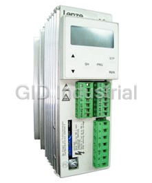
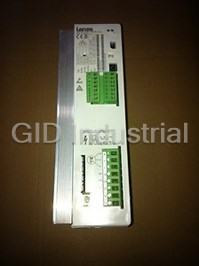

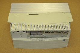


What they say about us
FANTASTIC RESOURCE
One of our top priorities is maintaining our business with precision, and we are constantly looking for affiliates that can help us achieve our goal. With the aid of GID Industrial, our obsolete product management has never been more efficient. They have been a great resource to our company, and have quickly become a go-to supplier on our list!
Bucher Emhart Glass
EXCELLENT SERVICE
With our strict fundamentals and high expectations, we were surprised when we came across GID Industrial and their competitive pricing. When we approached them with our issue, they were incredibly confident in being able to provide us with a seamless solution at the best price for us. GID Industrial quickly understood our needs and provided us with excellent service, as well as fully tested product to ensure what we received would be the right fit for our company.
Fuji
HARD TO FIND A BETTER PROVIDER
Our company provides services to aid in the manufacture of technological products, such as semiconductors and flat panel displays, and often searching for distributors of obsolete product we require can waste time and money. Finding GID Industrial proved to be a great asset to our company, with cost effective solutions and superior knowledge on all of their materials, it’d be hard to find a better provider of obsolete or hard to find products.
Applied Materials
CONSISTENTLY DELIVERS QUALITY SOLUTIONS
Over the years, the equipment used in our company becomes discontinued, but they’re still of great use to us and our customers. Once these products are no longer available through the manufacturer, finding a reliable, quick supplier is a necessity, and luckily for us, GID Industrial has provided the most trustworthy, quality solutions to our obsolete component needs.
Nidec Vamco
TERRIFIC RESOURCE
This company has been a terrific help to us (I work for Trican Well Service) in sourcing the Micron Ram Memory we needed for our Siemens computers. Great service! And great pricing! I know when the product is shipping and when it will arrive, all the way through the ordering process.
Trican Well Service
GO TO SOURCE
When I can't find an obsolete part, I first call GID and they'll come up with my parts every time. Great customer service and follow up as well. Scott emails me from time to time to touch base and see if we're having trouble finding something.....which is often with our 25 yr old equipment.
ConAgra Foods