

 Manufacturers
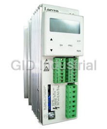
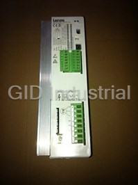
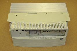
LENZE AC TECH EVF8201-E
Description
Lenze AC Tech EVF8201-E Inverters - Variable Frequency Inverter Output: 2.6AMP 230VAC Input: 1/N/PE AC 230V 5.0A 50/60Hz
Part Number
EVF8201-E
Price
Request Quote
Manufacturer
LENZE AC TECH
Lead Time
Request Quote
Category
PRODUCTS - E
Specifications
Degree of pollution
VDE 0110 part 2 pollution degree 2
Humidity class
Humidity class F without condensation (average relative humidity 85 %)
Insulation strength
Overvoltage category III according to VDE 0110
Vibration resistance
Germanischer Lloyd, general conditions
Features
- Accessories for assembling and connecting the inverters
- Application examples
- Order forms
- Static frequency inverters for controlling three-phase AC motors
Datasheet

Extracted Text
EDB8200UE 00398283 Operating Instructions Lenze Postfach 101352 ,31763 HAMELN K35.0110-3 Global Drive Frequency inverters 8200 series Typ Id.-NR Fert.-Nr Serien-Nr. Eingang1 Eingang2 These Operating Instructions are valid for the 82XXcontrollers of the versions: 33.820X- E- 1x. 1x (8201 - 8204) 33.8202- E- 1x. 1x -V002 reduced assembly depth (8202) Type Design: B = Module C= Cold Plate E= Enclosure IP20 Hardware level and index Software level and index Variant Explanation Corresponds to the German edition of 16/06/1997 Edition of: 02/10/1997 Contents 1 Preface and general information ........................... 1-1 1.1 About these Operating Instructions .......................... 1-1 1.1.1 Terminology used ............................... 1-1 1.1.2 What is new? .................................. 1-2 1.2 Scope of delivery ..................................... 1-2 1.3 Legal regulations ..................................... 1-3 2 Safety information ...................................... 2-1 2.1 General safety information............................... 2-1 2.2 Layout of the safety information ........................... 2-3 2.3 Residual hazards ..................................... 2-4 3 Technical data ......................................... 3-1 3.1 General data/application conditions......................... 3-1 3.2 Rated data (Operation with 150 % overload)................... 3-2 3.2.1 Types 8201 to 8204 ............................. 3-2 3.3 Fuses and cable cross-sections........................... 3-4 3.3.1 Single drives with 150 % overload.................... 3-4 3.4 Dimensions ......................................... 3-4 4 Installation ............................................ 4-1 4.1 Mechanical installation ................................. 4-1 4.1.1 Important notes................................. 4-1 4.1.2 Standard assembly with fixing rails or fixing angles......... 4-3 4.1.2.1 Types 8201 to 8204 ...................... 4-3 4.1.2.2 Type 8202-V002 (reduced assembly depth)....... 4-4 4.1.3 DIN-rail assembly ............................... 4-5 4.2 Electrical installation................................... 4-6 4.2.1 Important notes................................. 4-6 4.2.2 Power connections .............................. 4-7 4.2.2.1 Mains connection ........................ 4-7 4.2.2.2 Motor connection ........................ 4-7 4.2.2.3 Connection diagram....................... 4-9 4.2.3 Control connections.............................. 4-10 4.2.3.1 Control cables........................... 4-10 4.2.3.2 Assignment of the control terminals............ 4-10 4.2.3.3 Connection diagrams...................... 4-12 4.3 Installation of a CE-typical drive system...................... 4-13 820XBA1097 i Contents 5 Commissioning......................................... 5-1 5.1 Before you switch on .................................. 5-1 5.2 Short set-up (Factory setting)............................. 5-2 5.2.1 Switch-on sequence ............................. 5-2 5.2.2 Factory setting of the most important drive parameters...... 5-3 5.3 Adapt machine data ................................... 5-4 5.3.1 Determine speed range (fdmin, fdmax)................. 5-4 5.3.2 Adjustment of acceleration and deceleration times (Tir , T if).. 5-6 5.3.3 Setting of the current limit (Imax)..................... 5-7 5.4 Optimisation of the operating characteristic of the drive........... 5-8 5.4.1 Select the control mode........................... 5-8 5.4.1.1 Optimisationof V/f-characteristic controlwithautoboost...... 5-11 5.4.1.2 Optimisation of V/f-characteristic control......... 5-13 6 During operation ....................................... 6-1 7 Configuration .......................................... 7-1 7.1 Basics ............................................ 7-1 7.2 Code table ......................................... 7-2 8 Troubleshooting and fault elimination ....................... 8-1 8.1 Troubleshooting ...................................... 8-1 8.1.1 Display at the controller ........................... 8-1 8.1.2 Display at the operating module ..................... 8-1 8.1.3 Maloperation of the drive .......................... 8-2 8.2 Fault analysis using the history buffer....................... 8-2 8.3 Fault indications...................................... 8-3 8.4 Reset of fault indications................................ 8-5 9 Accessories (Overview) .................................. 9-1 9.1 Accessories for all types ................................ 9-1 9.2 Software ........................................... 9-2 9.3 Type-specific accessories ............................... 9-2 10 Index ................................................ 9-3 ii 820XBA1097 Preface and general information 1 Preface and general information 1.1 About these Operating Instructions ... -These Operating Instructions help you to connect and set up the 82XX frequency inverter. They contain safety information which must be observed. -All persons who work on and with 82XX frequency inverters must have the Operating Instructions available and observe all relevant notes and instructions. -The Operating Instructions must always be in a complete and perfectly readable state. 1.1.1 Terminology used Term In the following text used for 82XX Any frequency inverter of the series 8200, 8210, 8220, 8240 Controller 82XX frequency inverter Drive system Drive systems with 82XX frequency inverters and other Lenze drive components 820XBA1097 1-1 1.1.2 What is new? Material Edition of Important Content no. 375134 05/10/1994 8200/8210 Short Instructions 375190 13/02/1995 8200/8210 Operating Instructions 398283 02/10/1997 replaces 375134-Contents only for 8200 replaces 375190-Complete revision of the contents -Complete editorial revision 1.2 Scope of delivery Scope of delivery Important -1 82XX frequency inverter After receipt of the delivery, check immediately whether the scope of supply matches with the accompanying-1 Operating Instructions papers. Lenze does not accept any liability for deficiencies -1 accessory kit (components for claimed subsequently. the mechanical and electric Claim installation) -visible transport damage immediately to the forwarder. -visible deficiencies/incompleteness immediately to your Lenze representative. 1-2 820XBA1097 Preface and general information 1.3 Legal regulations L La ab be ellin lling g Nameplate CE mark Manufacturer Conforms to the EC Low Voltage Lenze GmbH & Co KG Directive Postfach 101352 D-31763 Hameln Application 82XX frequency inverter as directed-must only be operated under the conditions prescribed in these Instructions. -are components - used for open and closed loop control of variable speed drives withasynchronous standard motors, reluctance motors, PM-synchronous motors with asynchronous damping cage. - used for installation into a machine. - used for assembly together with other components to form a machine. -are electric units for the installation into control cabinets or similar enclosed operating housing. -comply with the requirements of the Low-Voltage Directive. -are not machines for the purpose of the Machinery Directive. -are not to be used as domestic appliances, but only for industrial purposes. Drive systems with 82XX frequency inverters -comply with the EMC Directive if they are installed according to the guidelines of CE-typical drive systems. -canbeused - on public and non-public mains. - in industrial as well as residential and commercial premises. -The user is responsible for the compliance of his application with the EC directives. Any other use shall be deemed inappropriate! 820XBA1097 1-3 Liability-The information, data and notes in these Operating Instructions met the state of the art at the time of printing. Claims referring to drive systems which have already been supplied cannot be derived from the information, illustrations, and descriptions given in these Operating Instructions. -The specifications, processes, and circuitry described in these Operating Instructions are for guidance only and must be adapted to your own specific application. Lenze does not take responsibility for the suitability of the process and circuit proposals. -The indications given in these Operating Instructions describe the features of the product without warranting them. -Lenze does not accept any liability for damage and operating interference caused by: - disregarding these Instructions - unauthorized modifications to the controller - operating errors - improper working on and with the controller Warranty-Warranty conditions: see Sales and Delivery Conditions of Lenze GmbH & Co KG. -Warranty claims must be made immediately after detecting defects or faults. -The warranty is void in all cases where liability claims cannot be made. Di Dis sp po os sa al l Material recycle dispose Metal-- Plastic-- Printed-board assemblies -- 1-4 820XBA1097 Safety information 2 Safety information 2.1 General safety information Safety and application notes for controllers (to: Low-Voltage Directive 73/23/EEC) 1. General to the regulations of the EC Directive 89/392/EEC (Machinery Directive); EN 60204 must be observed. During operation, drive controllers may have, according Commissioning (i.e. starting of operation as directed) is to their type of protection, live, bare, in some cases also only allowed when there is compliance with the EMC movable or rotating parts as well as hot surfaces. Directive (89/336/EEC). Non-authorized removal of the required cover, The drive controllers meet the requirements of the Low inappropriate use, incorrect installation or operation, Voltage Directive 73/23/EEC. The harmonized standards creates the risk of severe injury to persons or damage to of the prEN 50178/ DIN VDE 0160 series together with material assets. EN 60439-1/DIN VDE 0660 part 500 and EN 60146/DIN Further information can be obtained from the VDE 0558 are applicable to drive controllers. documentation. The technical data and information on the connection All operations concerning transport, installation, and conditions must be obtained from the nameplate and the documentation and must be observed in all cases. commissioning as well as maintenance must be carried out by qualified, skilled personnel (IEC 364 and CENELEC HD 384 or DIN VDE 0100 and IEC report 664 or DIN VDE 3. Transport, storage 0110 and national regulations for the prevention of Notes on transport, storage and appropriate handling accidents must be observed). must be observed. Climatic conditions must be observed according to According to this basic safety information qualified skilled personnel are persons who are familiar with the prEN 50178. erection, assembly, commissioning, and operation of the product and who have the qualifications necessary for 4. Erection their occupation. The devices must be erected and cooled according to the regulations of the corresponding documentation. The drive controllers must be protected from 2. Application as directed inappropriate loads. Particularly during transport and Drive controllers are components which are designed for handling, components must not be bent and/or isolating installation in electrical systems or machinery. distances must not be changed. Touching of electronic components and contacts must be avoided. When installing in machines, commissioning of the drive controllers (i.e. the starting of operation as directed) is Drive controllers contain electrostatically sensitive prohibited until it is proven that the machine corresponds components which can easily be damaged by 820XBA1097 2-1 Safety information inappropriate handling. Electrical components must not 6. Operation be damaged or destroyed mechanically (health risks are Systems where drive controllers are installed must be possible!). equipped, if necessary, with additional monitoring and protective devices according to the valid safety regulations, e.g. law on technical tools, regulations for 5. Electrical connection the prevention of accidents, etc. Modifications of the When working on live drive controllers, the valid national drive controllers by the operating software are allowed. regulations for the prevention of accidents (e.g. VBG 4) After disconnecting the drive controllers from the supply must be observed. voltage, live parts of the controller and power The electrical installation must be carried out according connections must not be touched immediately, because to the appropriate regulations (e.g. cable cross-sections, of possibly charged capacitors. For this, observe the fuses, PE connection). More detailed information is corresponding labels on the drive controllers. included in the documentation. During operation, all covers and doors must be closed. Notes concerning the installation in compliance with EMC - such as screening, grounding, arrangement of 7. Maintenance and servicing filters and laying of cables - are included in the The manufacturer’s documentation must be observed. documentation of the drive controllers. These notes must also be observed in all cases for drive controllers with the CE mark. The compliance with the required limit This safety information must be kept! values demanded by the EMC legislation is the responsibility of the manufacturer of the system or The product-specific safety and application notes machine. in these Operating Instructions must also be observed! 2-2 820XBA1097 Safety information 2.2 Layout of the safety information -All safety notes have a uniform layout: - The icon characterizes the type of danger. - The signal word characterizes the severity of danger. - The note describes the danger and suggests how to avoid the danger. Signal word Note Icons used Signal words Warning of Warning of Danger! Warns of impending dangeU. danger to hazardous Consequences if disregarded: persons electrical Death or very severe injuries. voltage Warning! Warns of potential, very hazardous situations. Warning of a general danger Possible consequences if disregarded: Death or very severe injuries. Caution! Warns of potential, hazardous situations. Possible consequences if disregarded: Light or minor injuries. Warning of Stop! Warns of potential damage to material . damage to Possible consequences if disregarded: material Damage of the controller/drive system or its environment . Other notes Note! This note designates general, useful notes. If you observe it, handling of the controller/drive system is made easier. 820XBA1097 2-3 Safety information 2.3 Residual hazards Operator’s safety After mains disconnections, the power terminals U, V, W and + U ,-U remain live for at G G least three minutes. -Before working on the controller, check that no voltage is applied to the power terminals. Protection of Cyclic connection and disconnection of the controller supply voltage at L1, L2, L3 or + U , G devices -U may overload the internal input current load: G -Allow at least 3 minutes between disconnection and reconnection. Overspeeds Drive systems can reach dangerous overspeeds (e. g. setting of inappropriately high field frequencies): -The controllers do not offer any protection against these operating conditions. Use additional components for this. 2-4 820XBA1097 Technical Data 3Technicaldata 3.1 General data/application conditions Field Values Vibration resistance Germanischer Lloyd, general conditions Humidity class Humidity class F without condensation (average relative humidity 85 %) P Pe errm miissi ssib blle e during transport of the controller: -25C⁄+70C t te em mp pe er ra at tur ure e r ra ange nges s during storage of the controller: -25C⁄+55C during operation of the controller: 0C⁄+40C without power derating +40C⁄+50C with power derating Permissible without power derating h$1000 m.a.m.s.l installation height h with power derating 1000 m a.m.s.l h$4000 m a.m.s.l Degree of pollution VDE 0110 part 2 pollution degree 2 Noise emission Requirements acc. to EN 50081-2, EN 50082-1, IEC 22G-WG4 (Cv) 21 Limit value class A to EN 55011 (industrial area) with mains filter Limit value class B to EN 55022 (residential area) with mains filter and installation into control cabinet Noise immunity Limit values maintained usig mains filter Requirements according to EN 50082-2, IEC 22G-WG4 (Cv) 21 Requirements Standard Severities ESD EN61000-4-2 3, i.e. 8 kV with air discharge 6 kV with contact discharge RF interference(enclosure) EN61000-4-3 3, i.e. 10 V/m; 27⁄1000 MHz Burst EN61000-4-4 3/4, i.e. 2 kV/5 kHz Surge EN 61000-4-5 3, i.e. 1.2/50‡s, (Surge on mains cable) 1 kV phase-phase, 2 kV phase-PE Insulation strength Overvoltage category III according to VDE 0110 Packaging (DIN Dust packaging 4180) Type of protection IP20 NEMA 1: Protection against contact Approvals CE: Low Voltage Directive Electromagnetic compatibility 820XBA1097 3-1 Technical Data 3.2 Rated data (Operation with 150 % overload) 3.2.1 Types 8201 to 8204 150 % overload Type 8201 8202 8203 8204 Order no. EVF8201-E EVF8202-E EVF8203-E EVF8204-E Va Var ri ia an nt t ” ”r re ed du uc ced ed a as ss se em mb blly y Type 8202-V002 d de ep pt th h” ” Order no. EVF8202-E- V002 Mains voltage V [V] 190VÆ0%$V$260VÆ0% ; 45Hz⁄65HzÆ0% rated rated Alternative DC supply V [V] 270VÆ0%$V$360VÆ0% DC DC 4) Mains current I [A] mains with mains filter/mains choke 4.2 7.5 12.5 17.0 without mains filter/mains choke 5.0 9.0 15.0 - Data for mains operation with 1 AC / 230 V / 50 Hz/60 Hz; 270$V$275V DC M Mo otto or r p pow ower er ( (4 4 p po olle e A AS SM M) ) P [kW] 0.37 0.75 1.5 2.2 rated at 9.2 kHz* at 9.2 kHz* P [hp] 0.5 1.0 2.0 2.9 rated Output power U, V, W S [kVA] 1.0 1.5 2.7 3.6 N9.2 at 9.2 kHz* 1) Output power + U ,-U P [kW] 0.0 0.0 0.0 0.0 G G DC Output current I [A] 2.6 4.0 7.0 9.5 rated 2) Max. output current for 60s I [A] 3.9 6.0 10.5 14.2 Nmax 3) Motor voltage V [V] 0- 3V /0Hz⁄50Hz, if required up to 240Hz M mains Power loss (Operation with I ) P [W] 30 50 70 100 N v 3-2 820XBA1097 Technical Data 150 % overload Type 8201 8202 8203 8204 Order no. EVF8201-E EVF8202-E EVF8203-E EVF8204-E Va Var ri ia an nt t ” ”red redu uced ced a as ss se em mb bly ly Type 8202-V002 de dept pth” h” Order no. EVF8202-E- V002 Power derating [%/K] 40C< T <50C: 2,5%/K amb [%/m] 1000 m a.m.s.l. h$4000 m a.m.s.l.: 5%/1000 m Fi Fie el ld d Resolution Absolute 0.05 Hz f fr re eq que uen nc cy y Digital setpoint AccuracyÆ0.05 Hz selection A An nal alo og g s se et tp po oiin nt t LinearityÆ0.5 % (max. selected signal level, 5V or 10V) s se elle ec ct tiio on n Temperature 0⁄40C: + 0.4 % sensitivity OffsetÆ0.3 % Weight m[kg] 1.0 1.3 2.2 2.2 Variant 1.0 1) This power can be additionally obtained when operating a matching motor 2) The currents apply to a periodical load cycle with 1 minute overcurrent with the current mentioned here and 2 minutes base load with 75% I . Nrated 3) With mains choke/mains filter: max. output voltage = approx. 96 % of the mains voltage 4) Observe the N-conduction load when having a symmetrical mains distribution! (See electrical installation) * Chopper frequency of the inverter 820XBA1097 3-3 Technical Data 3.3 Fuses and cable cross-sections 3.3.1 Single drives with 150 % overload The table values are valid for the operation of 82XX controllers as single drives with a matching motor and 150 % overload. Ty Typ pe e Mains input L1,N,PE/ motorconnection U,V, W,PE Operation without mains filter/mains choke Operation with mains filter/mains choke Fuse E.l.c.b. Cable Fuse E.l.c.b. Cable 1) 1) F1, F2, F3 cross-section F1, F2, F3 cross-section 2 2 VDE UL VDE mm AWG VDE UL VDE mm AWG 8201 M 10A - C 10A 1.5 15 M 10A - C10A 1.5 15 8202 M 15A - C 16A 2.5 13 M 15A - C16A 2.5 13 [1.5] [15] 8203 M 20A - C 20A 4 11 M 15A - C16A 2.5 13 [1.5] [15] 8204 - - - - - M 20A - C20A 4 11 [2.5] [13] Values in square brackets are valid for motor connection 1) Observe national and regional regulations (e. g. VDE/EVU)! 3.4 Dimensions The controller dimensions depend on the mechanical installation (see chapter 4.1). 3-4 820XBA1097 Installation 4 Installation 4.1 Mechanical installation 4.1.1 Important notes -Use the controllers only as built-in devices! -If the cooling air contains pollutants (dust, fluff, grease, aggressive gases): - take suitable preventive measures , e.g. separate air duct, installation of filters, regular cleaning, etc. -Observe free space! - You can install several controllers next to each other without free space in a control cabinet. - Ensure unimpeded ventilation of cooling air and outlet of exhaust air! - Allow a free space of 100 mm at the top and at the bottom. -Do not exceed the ambient temperature permissible during operation (see chapter. 3.1) -With continous oscillations or vibrations: - Check whether shock absorbers are necessary. 820XBA1097 4-1 Installation Possible mounting positions -In vertical position at the back of the control cabinet, terminals point to the front: - With attached fixing rails. - With special fixing unit on one or two DIN rails. -Turned by 90(flat assembly on the backside of the control cabinet): - Insert the attached fixing rail into the guides at the heat sink. -Horizontally with an additional fan. -On a pivoting frame for assembly depths < 198 mm: - Therefore easy handling and installation of the front interfaces possible. 4-2 820XBA1097 Ei Ei NrFer Installation 4.1.2 Standard assembly with fixing rails or fixing angles 4.1.2.1 Types 8201 to 8204 g 1) 3) ePocaf0h132,HAMN Rp.-Nt.-Senngang1ngang2 2) db ce k a K35.0074 FIG 4-1 Dimensions 8201 - 8204: Standard assembly 1) Fixing rail for side assembly 2) Observe the free space required for the connection cables 3) With attachable fieldbus or I/O module: Observe assembly depth and assembly space required for connection cables 3) [mm] a b c d e g k 8201 64 210 29 190 158 6.5 30 8202 64 210 29 190 198 6.5 30 8202- V002 64 210 29 190 158 6.5 30 8203 / 8204 83 283 38 263 211 6.5 30 820XBA1097 4-3 Ty Id rie-Nr. EL6317135st Lenz Installation 4.1.2.2 Type 8202-V002 (reduced assembly depth) This variant is equipped with a heat sink with a smaller surface. Observe the following points to comply with the technical data: -Assembly on an unpainted, metallic assembly board. 2-Area > 0.15 m . -Sheet thickness at least 2 mm. 4-4 820XBA1097 Installation 4.1.3 DIN-rail assembly 1) Lezne 3H,PhtfosN c3 2)12Rngng-Nt.-enp.rSeEiEi b c2 1) c1 ea K35.0071 FIG 4-2 Dimensions 8201 - 8204: DIN-rail assembly 1) 8201/8202: Assembly on a DIN rail (middle) or on two DIN rails (top and bottom) possible 8203 - 8204: Assembly on two DIN rails 2) Observe the free space required for the connection cables 3) With attachable fieldbus or I/O module: Observe assembly depth and assembly space required for connection cables 3) [mm] a b c1 c2 c3 e 8201 64 188 16 98 149 173 8202 64 188 16 98 149 213 8203 / 8204 83 258 16 - 149 237 820XBA1097 4-5 Ty Id FeNr ri-Nr. nga nga AMELac1013523176 3) Installation 4.2 Electrical installation 4.2.1 Important notes -Ensure appropriate activation when using current-operated e.l.c.b.s. -For information on the installation according to EMC see chapter 4.3 -Prior to assembly and service operations, the personnel must be free of electrostatic charge. -Unused control inputs and outputs should be covered with plugs. -In case of condensation, connect the controller to the mains voltage only after the visible humidity has evaporated. -Please observe the restricitons of each mains type! Mains Operation of the controller Notes With grounded neutral No restrictions Observe controller ratings Operation of several 820X-Observe the load of the shared controllers connected to a mains N-conductor. 3AC/ N/ PEand symmetrical - r.m.s. current, see chapter 3.2 distribution to the three outer -Possibly enlarge the cross-section conductors excepted of the N-conductor. With isolated neutral Operation with recommended-Mains filter will be destroyed if (IT mains) mains filtersisnot possible ”earth fault” occurs. -Contact Lenze. With grounded phase Operation only possible with one Contact Lenze variant DC supply via + UG/-UG DCvoltagemust besymmetrical Controller will be destroyed when to PE grounding + UG-Leiter or -UG-Leiter 4-6 820XBA1097 Installation 4.2.2 Power connections 4.2.2.1 Mains connection -Connect the mains cables with the screw terminals L1, L2, L3. - Tightening torques Terminals L1, L2, L3, + UG, -UG PE connection Type 8201 - 8204 0.5 ... 0.6 Nm (4.4 ... 5.3 lbin) 3.4 Nm (30 lbin) 4.2.2.2 Motor connection Because of the EMC safety we recommend the use of screened motor cables only. Screen connection -820X: On the front FAST-ON connector. -Connect the motor cables to the screw terminals U, V, W anschließen. - Observe correct pole connection. - Tightening torques Terminals Screen/ U, V, W PE connection T1, T2 Type strain relief 0.5 ... 0.6 Nm 3.4 Nm 8201 - - - 8204 (4.4 ... 5.3 lbin) (30 lbin) -Switching on the motor side of the controller is permitted - for safety switch off (emergency switch off). - during operation under load. 820XBA1097 4-7 Installation -Themotorcableshould beasshort aspossiblebecauseof thepositiveeffect onthedrivecharacteristic. - FIG 4-3 shows the relation between motor-cable length and the possible required output filters. - For group drives (several motors connected to one controller) it is necessary to calculate the resulting cable length l : res fl IresSum of all motor cable lengthsNo.ofmotorcables - When using unscreened motor cables, the data indicated in FIG 4-3 are valid for the double motor-cable length. - Please contact Lenze when the absolute or resulting motor-cable lengths are > 200 m. Type Permissible control mode C014 8201 8202 - -0 0- -,, - -1 1- -,, --2 2--,, --3 3-- - -2 2- -, , - -3 3- - --2 2--,, --3 3-- 8203 -2 -2--,, --3 3-- + + m mot oto or r f fiillt te er r/ / + + s sin ine e ffiilt lte er r 8204 0 15 25 50 100 200 Motor-cable length (resulting), screened in m FIG 4-3 Output filters additionally required in the motor cable 4-8 820XBA1097 Installation 4.2.2.3 Connection diagram L1 N/L2 F1 Fuse PE F2* Fuse only for supply with 2AC / PE / 190-260V K10 Mains contactor K10* Mains contactor only for supply F1 F2* K10 with 2AC / PE / 190-260V Z1 Mains filter/mains choke, see Accessories K10 K10* ϑRB Z2 Motor filter/sine filter, see K10 Accessories Z1 Z3 Brake chopper/brake module, see Accessories RB Brake resistor, see Accessories JTemperature monitoring - brake RB resistor RB X1 Terminal strip in control cabinet L1 N PE 8204 operation only with assigned PE mains choke/mains filter +UG 8201... 8204 -UG PE RB1 RB2 +UG -UG Z3 PE U V W PE Z2 -X1 M 3~ PE K35.0135 FIG 4-4 820X power connections 820XBA1097 4-9 Installation 4.2.3 Control connections 4.2.3.1 Control cables -We recommend the unilateral screening of all cables for analog signals to avoid signal distortion. -Connect the screens of the control cables as follows: -820X: On the front FAST-ON connector. -If the control cables are interrupted (terminal strips, relays), the screens must be reconnected over the shortest possible distance. -Connnect the fixing screw of the setpoint potentiometer to PE. 4.2.3.2 Assignment of the control terminals 6220 287 E18 9E2 E3 K11 E4 K12 39 K14 K35.0026 FIG 4-5 Position of the control terminals 4-10 820XBA1097 Installation Terminal Use Level Data (Factory setting is printed in bold) Analog 7 GND 1 iin nput puts s 8 Setpoint input, 5- 6 0to20mA Resolution: 9 bit reference: 5- 6 4to20mA Linearity fault:0.5 % 6 5 Terminal 7 3- 4 0to5 V Temperature fault: 0.3 % (0...+ 40 4 3 (0 to 10V)C) 1- 2 0to10V 2 1 Input resistance V Vo olltta ag ge e s siig gn na all:: > > 1 10 00 0 k k Jumper Current signal: 250 9 Supply for setpoint potentiometer 5.2V / 6mA Analog 62 Analog output, reference: terminal 7 0... 6 V / 2 Resolution: 8 bit mA (Field frequency) output Digital 20 Voltage supply for digital inputs iin nput puts s 12 V/20 mA 28 Controller enable HIGH H HIIG GH H::1 12V 2 V...... 3 30V 0 V L LO OW W:: 0 0 V V ...... 3 3 V V E4 CW rotation/ CW: LOW CCW rotation (CW/ CCW) CCW: HIGH E3 DC-injection brake HIGH J JO OG G f fr re eq que uen nc ciie es s B Biin na ar ry y c co od de e E2 2 20H 0Hz z,, 30H 30Hz z,, 4 40 0H Hz z E1 39 GND 2 (reference for external voltages) Terminal Use Relay position Data (switched) (Factory setting is printed in bold) Relay K11 Relay output normally-closed contact opened 24 V AC / 3,0 A or o ou uttp put ut (TRIP) 60 60 V V D DC C // 0. 0.5 5 A A K K1 1 K22 Relay mid-position contact K24 Relay output normally-open contact closed (TRIP) 820XBA1097 4-11 Installation 4.2.3.3 Connection diagrams 82XX GND 2 GND 1 K1 Vref 3k 3k 3k 3k 3k Vcc 5,2V 62 78 9 K11 K12K14 20 28 E1 E2 E3 E4 39 PE R 1k K35.0077-3 ≥ FIG 4-6 Control connections: Supply with internal control voltage 82XX GND 2 GND 1 K1 3k 3k 3k 3k 3k Vref Vcc 5,2V 62 7 8 9 K11 K12 K14 20 28 E1 E2 E3 E4 39 PE - 12...30V + R ≥ 1k K35.0077-4 FIG 4-7 Control connections: External voltage supply (+12 V ... +30 V) GND1 Reference for internal voltages GND2 Reference for external voltages GND1 and GND2 have a potential isolation inside the unit. 4-12 820XBA1097 3k3 3k3 >100k >100k Installation 4.3 Installation of a CE-typical drive system General-The user is responsible for the compliance of his application with the EC directives. notes - If you observe the following measure you can be sure that the drive system will not cause any EMC problems, i.e. comply with the EMC Directive when running the machine. - If devices which do not comply with the CE requirement concerning noise immunity EN 50082-2 are operated close to the controller, these devices may be interfered electromagnetically by the controllers. Assembly-Connect controller, mains choke, and mains filter to the grounded mounting plate with a wire of large a cross-section as possible: - Mounting plates with conductive surfaces (zinc-coated, stainless steel) allow permanent contact. - Varnished boards should not be used for installation in accordance with EMC -If you use several mounting plates: - Connect as much surface as possible of the mounting plates (e.g. with copper bands). -Ensure the separation of motor cable and signal or mains cable. -Do not use the same terminal strip for mains input and motor output. -Cable guides as close as possible to the reference potential. Unguided cables have the same effect as aerials. Filters-Use mains filters or RFI filters and mains chokes which are assigned to the controller: - RFI filters reduce impermissible high-frequency interference to a permissible value. - Mains chokes reduce low-frequency interferences which depend on the motor cable and its length. - Mains filters combine the functions of mains choke and RFI filter. 820XBA1097 4-13 Installation Screening-Connect the screen of the motor cable with the controller - to the screen connection of the controller. - additionally to the mounting plate with a surface as large as possible. - Recommendation: For the connection, use ground clamps on bare metal mounting surfaces. -If contactors, motor-protecting switches or terminals are located in the motor cable: - Connect the screens of the connected cables also to the mounting plate, with a surface as large as possible. -Connect the screen to PE, with a surface as large as possible. - Metal glands at the motor terminal box ensure a connection of the screen and the motor housing. -If the mains cable between mains filter and controller is longer than 300 mm: - Screen mains cables. - Connect the screen of the mains cable directly to the inverter and to the mains filter and connect it to the mounting plate with as large a surface as possible. -Use of a brake chopper: - Connect the screen of the brake resistor cable directly to the mounting plate, at the brake chopper and the brake resistor with as large a surface as possible. - Connect the screen of the cable between controller and brake chopper directly to the mounting plate, at the inverter and the brake chopper with a surface as large as possible. -Screen the control cables: - Connect both screen ends of the digital control cables. - Connect one screen end of the analog control cables. - Always connect the screens to the screen connection at the controller over the shortest possible distance. -Application of the controllers 821X/822X/824X in residential areas: - Use an additional screen damping10 dB to limit the radio interference. This is usually achieved by installation in enclosed and grounded control cabinets made of metal. Grounding-Ground all conductive metal components (controller, mains filter, motor filter, mains choke) using suitable cables connected to a central point (PE bar). -Maintain the minimum cross-sections prescribed in the safety regulations: - For EMC, not the cable cross-section is important, but the surface and the contact with a cross-section as large as possible, i.e. large surface. 4-14 820XBA1097 Installation n Netz n PE n F1 n K10 n Z1 n n PE PES PE PES RB Lx PE PES PES 82XX +UG GND 2 -UG PES PES GND 1 K1 PE RB1 RB2 +UG -UG Vcc Vref Z3 K11 K12 K14 PE U V W 62 78 9 20 28 E1 E2 E3 E4 39 PES PES PES PES PE Z2 -X1 PES M PE PE 3~ K35.0082 FIG 4-8 Example for an installation in accordance with the EMC regulations: F1 Fuse K10 Mains contactor Z1 Mains filter ”A” or ”B”, see Accessories Z2 Motor filter/sine filter, see Accessories Z3 Brake module/brake chopper, see Accessories -X1 Terminal strip in control cabinet RB Brake resistor PES HF screen because of a PE connection with a surface as large as possible (see ”Screening” in this chapter) n Number of phases 820XBA1097 4-15 Installation 4-16 820XBA1097 Commissioning 5 Commissioning The controllers are factory-set to drive a corresponding four-pole standard motor with 230/400V, 50Hz. Further settings are not necessary. Only a few settings via the 8201 BB operating module or a fieldbus module are necessary to adapt your drive to your application. The steps required are summarized in chapter 5.3 and in chapter 5.4. 5.1 Before you switch on Prior to initial switch-on of the controller, check the wiring for completeness, short-circuit, and earth fault: -Power connection: - Via terminals L1/N - 820X. - Alternatively via terminals +UG, -UG (DC-group drive) -Control terminals: - Reference potential for the control terminals is terminal 39. - Controller enable: terminal 28 - Selection of direction of rotation: terminal E3 or E4 - External setpoint selection: terminals 8, 9 - Check jumper position! Factpr settomg: 0 - 10 V (see page 4-10). - During operation with an internal voltage supply via terminal 20, bride the terminals 7 and 39. 820XBA1097 5-1 Commissioning -In case of condensation connect the controller to mains voltage only after the visible humidity has evaporated. -The plug-in power terminals of the 820X controller must only be connected or disconnected when no voltage is applied. Maintain the switch-on sequence! 5.2 Short set-up (Factory setting) 5.2.1 Switch-on sequence Step 1.Switch on mains voltage 2.Select the direction of rotation.-CW rotation: - Apply a LOW signal to terminal E4 (0...+ 3V). -CCW rotation: - Apply a HIGH signal to terminal E4 (+ 12...+ 30V). 3.Select the setpoint. Apply a voltage 0...+ 10 V to terminal 8. 4.Enable the controller. Apply a HIGH signal (+ 12...+ 30V) to terminal 28. 5.The drive is now operating according to factory setting. 5-2 820XBA1097 Commissioning 5.2.2 Factory setting of the most important drive parameters Setting Code Factory setting Adaption to the application Operating mode C001 -0- Setpoint selection via terminal 8 See code table, Control via terminals chapter 7.2 Parameter setting via 8201BB Terminal configuration C007 -0- E4 E3 E2 E1 See code table, CW/CCWDC injection brake JOG1/2/3 chapter 7.2 Machine data Chapter 5.3 ff. Speed range Min. field frequency C010 0.0 Hz Chapter 5.3.1 Max. field C011 50.0 Hz frequency Acceleration Chapter 5.3.2 Acceleration time C012 5.0 s an and d d de ec ce ele ler ra at tiio on n Deceleration time C013 5.0 s times Current limit Motor mode C022 150 % Chapter 5.3.3 va vallu ue es s Generator mode C023 80 % Drive performance Chapter 5.4 ff. Current, Operating mode C014 -0- Linear characteristic Vf with auto V/f d boost characteristic torque, c co on nttr ro oll p po ow we er r V/f rated frequency C015 50.0 Hz-with auto characteristic boost, see c ch ha ap pt te er r V setting C016 type min 5.4.1.1 dependent -wi wit th hV V min min b boos oost t, , s se ee e Slip compensation C021 0% chapter 5.4.1.2 820XBA1097 5-3 Commissioning 5.3 Adapt machine data 5.3.1 Determine speed range (f f dmin, dmax) Code Name Possible settings IMPORTANT Lenze Selection Info C010 Minimum field 0.0 0.0 {0.1Hz} 480.0 frequency C011 Maximum field 50.0 30.0 {0.1Hz} 480.0 frequency Function The speed range required for the application can be selected here by determing the field frequencies f and f : dmin dmax -f corresponds to the speed at 0 % speed setpoint selection. dmin -f corresponds to the speed at 100 % speed setpoint selection. dmax Adjustment Relation between field frequency and synchronous motor speed: -1 f60 n synchronous motor speed [min ] rsyn dmax nrsyn f max. field frequency [Hz] p dmax p number of pole pairs Example: 4 pole asynchronous motor: 5060 –1 n1500 min rsyn p= 2, f =50Hz dmax 2 5-4 820XBA1097 Commissioning Important-With the setting of f >f the field frequency is limited to f . dmin dmax dmax -When selecting the setpoint by means of JOG values, f acts as limitation. dmax -f is an internal standardization variable: dmax - Use the LECOM interface only for important modifications, when the controller is inhibited. -Observe the maximum motor speed! -f is only effective under the following conditions: dmin - With analog setpoint selection. - With the motor potentiometer function ”DOWN”. Special features -With field frequencies f >240Hz: d - The overcurrent switch-off can be activated. fd C011 (fdmax) C010 (fdmin) 0 % 100 % K35.0062 820XBA1097 5-5 Commissioning 5.3.2 Adjustment of acceleration and deceleration times (T ,T ) ir if Code Name Possible settings IMPORTANT Lenze Selection Info C012 Acceleration time 5.0 0.0 {0.1s} 999.0 T ir C013 Deceleration time 5.0 0.0 {0.1s} 999.0 T if Function The accleration and deceleration times determine the time required by the drive to follow a setpoint change. Adjustment-The acceleration and deceleration times refer to a change of the field frequency from 0 Hz to the max. field frequency set under C011. -Calculate the times T and T , which must be set under C012 and C013. ir if -t and t are the times required for the change between f and f : ir if d1 d2 f f dmax dmax TtTtir ir if if ff ff d2 d1 d2 d1 Important Under unfavourable operating conditions, too short acceleration and deceleration times can lead to the deactivation of the controller under overload with the indication of TRIP OC5. In these events, the acceleration and deceleration times should be set short enough so that the drive can follow the speed profile without reaching I of the max controller. Special features The slope can be set between 0.095Hz/s and 780Hz/s. f /Hz d f dmax f d2 f d1 0 t t t ir if T T ir if K35.0063 5-6 820XBA1097 Commissioning 5.3.3 Setting of the current limit (I ) max Code Name Possible settings IMPORTANT Lenze Selection Info C022 I limit 150 30 {1 %} 150 max motor mode C023 I limit 80 30 {1 %} 110 max generator mode Function The controllers are equipped with a current-limit control which determines the dynamic response under load. The measured load is compared with the limit values set under C022 for motor load and under C023 for generator load. If the current-limit values are exceeded, the controller will change its dynamic response. Adjustment The acceleration and decleration time should be set short enough so that the drive can follow the speed profile without reaching I of the controller. max Drive characteristic-During acceleration: when reaching the limit - Expansion of the acceleration ramp. value -During deceleration: - Expansion of the deceleration ramp. -When the load increases at constant speed: - When the motor-current limit value is reached: Reduction of the field frequency to 10Hz. - When the generator-current limit value is reached: Increase the field frequency to the maximum frequency (C011). - Stop the field-frequency change if the load falls below the limit value. 820XBA1097 5-7 Commissioning 5.4 Optimisation of the operating characteristic of the drive By means of the following settings you can influence the current, torque and power characteristic or the connected motor. You can choose between the control modes ”V/f-characteristic control with auto boost” and ”V/f-characteristic control with constant V boost”. In chapter 5.4.1 you will find some more min information to help you with the selection. 5.4.1 Select the control mode Code Name Possible settings IMPORTANT Lenze Selection Info C014§Operating mode -0- -0- Linear characteristic Vf with Control d auto boost modes of the 2 voltage -1- Square characteristic Vf d characteristic with auto boost -2- Linear characteristic Vf with d constant V boost min 2 -3- Square characteristic Vf d with constant V boost min Function-Under C014 you can set the control mode and the voltage characteristic. -The V/f-characteristic control with auto boost enables a low-loss operation of single drives with standard three-phase AC motors with load-dependent V boost. min 5-8 820XBA1097 Commissioning C014 = -0- C014 = -1- Linear characteristic Square-law characteristic (e. g. for pumps, fans) VoutVout 100%100% Auto boost VminAuto boost Vmin 00 ff01d01d ffdNdN K35.0064 C014 = -2- C014 = -3- Linear characteristic Square-law characteristic (e. g. for pumps, fans) VoutVout 100%100% Vmin Vmin 00 ffdd0101 ffdNdNK35.0065 820XBA1097 5-9 Commissioning Help for decision Motor cable screened > 25 m screened$25 m unscreened > 50 m unscreened$50 m C014 recommended alternatively recommended alternatively Single drives With constant load -0- -2- -2- - With changing loads -0- -2- -2- - With heavy start conditions -0- -2- -2- - High dynamic posotioning and feed drives -0- - -2- - Lifts and hoists -0- -2- -2- - Pumps and fan drives -1- -3- -3- -2- Three-phase reluctance motors -2- - -2- - Three-phase sliding rotor motors -2- - -2- - Three-phase motors with assigned -2- - -2- - frequency-voltage characteristic Group drives (depending on the resultingflli(lll ) res 1 2 i motor-cable length) Simitas motors and loads -2- - -2- - Different motors and/or changing loads -2- - -2- - 5-10 820XBA1097 Commissioning 5.4.1.1 Optimisation of V/f-characteristic control with auto boost Codes required Code Name Possible settings IMPORTANT Lenze Selection Info C015 V/f-rated 50.0 30.0 {0.1Hz} 960.0 frequency C016 V setting *0{1%} 40 * type dependent min C021 Slip 00{1%} 12 compensation Setting sequence 1.If necessary, select V/f characteristic (C014). 2.Select V/f-rated-The V/f-rated frequency determines the slope of the V/f characteristic and has frequency (C015). considerable influence on the current, torque and power performance of the motor. -An internal mains voltage compensation compensates deviations in the mains during operation. They therefore do not have to be considered for the setting of C015. Adjustment Calculate the frequency to be set under C015 230V C015[Hz]rated motor frequency[Hz] V [V] rated motor C014 = -0- C014 = -1- Linear characteristic Square-law characteristic (e. g. for pumps, fans) VoutVout 100%100% Auto boost VminAuto boost Vmin 00 ff01d01d ffdNdN K35.0064 820XBA1097 5-11 Commissioning 3. Set the Vmin boost Load-dependentboost of the motor voltage in the field-frequency range below the (C016). V/f-rated frequency. C016 acts as gain factor of the auto-boost function. Adjustment In general, an adjustment is not necessary. An optimisation can be advantageous: For drives with very high starting torques: A Operate the motor under load. B Select the frequency setpoint. C Increase V until the required motor current (torque) occurs. min Too high settings of V can lead to a positive-feedback effect which activates the min TRIP ”Overcurrent” (OCx). For drives with square load torques (fans, pumps): A Operate the motor under load. B Select the frequency setpoint. C Adapt V until the motor is running steadily and smoothly over the whole fre- min quency range. Too high settings of V can activate the TRIP ”Overcurrent” (OCx) and lead to an min extensive motor temperature. For drives with special motors: A Operate the motor under load. B Select the frequency setpoint. C Increase V until the required motor current (torque) occurs. min Too high settings of V can lead to a positive-feedback effect which activates the min TRIP ”Overcurrent” (OCx). D Check the current consumption during idle-running when no load is applied 4 4.. S Se ett s slliip p c co om mp pen ens sa attiion on Rough setting by means of the motor data: ( (C C0 021) 21).. nn s Slip constant (C021) rsyn r s100% -1 n n synchronous motor speed [min ] rsyn rsyn -1 n rated speed to motor nameplate [min ] r f rated frequency to motor nameplate [Hz] f60 dr dr np Number of pole pairs rsyn p Precise setting: Change C021 under constant load until the speed is near the synchronous speed. If C021 is set to too high values, the drive may become instable (overcompensation). 5-12 820XBA1097 Commissioning 5.4.1.2 Optimisation of V/f-characteristic control Codes required Code Name Possible settings IMPORTANT Lenze Selection Info C015 V/f-rated 50.0 30.0 {0.1Hz} 960.0 frequency C016 V setting *0{1%} 40 * type dependent min C021 Slip 00{1%} 12 compensation Setting sequence 1.If necessary, select V/f characteristic (C014). 2.Select V/f-rated-The V/f-rated frequency determines the slope of the V/f characteristic and has frequency (C015). considerable influence on the current, torque and power performance of the motor. -An internal mains voltage compensation compensates deviations in the mains during operation. They therefore do not have to be considered for the setting of C015. Adjustment Calculate the frequency to be set under C015 230V C015[Hz]rated motor frequency [Hz] V [V] rated motor C014 = -2- C014 = -3- Linear characteristic Square-law characteristic (e. g. for pumps, fans) VoutVout 100%100% Vmin Vmin 00 ff01d01d ffdNdNK35.0065 820XBA1097 5-13 Commissioning 3. Set the Vmin boost-Load-independentboost of the motor voltage for field frequencies below the (C016). U/f-rated frequency. You can thus optimize the torque performance of the inverter drive. -It is absolutely necessary to adapt the asynchronous motor used, since otherwise, the motor can be destroyed by overtemperatue: Adjustment Please note the thermal characteristic of the connected motor under small field frequencies: -Usually, standard asynchronous motors with insulation class B can be operated for a short time with rated current and frequencies between 0Hz$f$25Hz. d -Please ask the motor manufacturer for the exact setting values for the motor current. A Operate the motor in idle running with a slip frequency of f : d -P$7.5 kW: f5Hz mot d -P7.5 kW: f2Hz mot d B Increase V until you reach the following motor current: min - Motor in short-term operation at 0Hz$f$25Hz: d with self-ventilated motors: I$I motor N motor with forced-ventilated motors: I I motor$Nmotor - Motor in permanent operation at 0Hz$f$25Hz: d with self-ventilated motors I$0.8kI motor N motor with forced-ventilated motors: I$I motor Nmotor 4 4. . S Se ett s slliip p c co om mp pen ens sa attiion on Rough setting by means of the motor data: ( (C C0 021) 21).. nn s Slip constant (C021) rsyn r s100% -1 n n synchronous motor speed [min ] rsyn rsyn -1 n rated speed to motor nameplate [min ] r f rated frequency to motor nameplate [Hz] dr f60 dr np Number of pole pairs rsyn p Precise setting: Change C021 under constant load until the speed is near the synchronous speed. If C021 is set to too high values, the drive may become instable (overcompensation). 5-14 820XBA1097 During operation 6 During operation -Replace defective fuses with the prescribed type only when no voltage is applied. There are no fuses in the controller. -Cyclic mains switching: - Do not switch on the controller more than every 3 minutes, otherwise the internal initial-current limitation can be overloaded. -Switching on the motor side: - Permissible for emergency switch-off. - Monitoring messages can be activated when switching the motor when the controller is enabled. -The plug-in connection terminals of the 820X controllers must only be connected or disconnected when no voltage is applied. -Depending on the controller settings, the connected motor can be overheated: - For instance, longer DC-braking operations. - Longer operation of self-ventilated motors at low speed. -The controllers generate an output frequency of up to 480 Hz when setting it correspondingly: - If an inappropriate motor is connected, a hazardous overspeed may occur. - With frequencies >240 Hz, 820X controllers can activate the over-current switch-off. 820XBA1097 6-1 During operation -If you use the function CW/CCW (selection of the direction of rotation) with the configuration C007 = -0- to -13-: - Thedrivecanreversethedirectionofrotationintheevent of a control-voltage failure or a cable break. -If you use the function ”Flying-restart circuit” (C142 = -2-, -3-) with machines with low inertia torque and friction: - The motor can start for a short time or reverse the direction of rotation for a short time after enabling the controller when the motor is in standstill. 6-2 820XBA1097 Configuration 7 Configuration 7.1 Basics -The configuration of the controller is used to adapt the drive to your applications. -For this, you have the following functions available: - Operating functions - Control function - Display functions - Monitoring functions -The possible function settings are organized in codes: - Codes are numerically sorted, starting from the code with the smallest number to the one with the highest number. All codes start with a ”C”. - They are listed in the code table. - Each code provides parameters which can be used to adjust and optimize your drive. -The configuration of the controller can be entered by means of the keypad of the 8201BB operating module or by means ofafieldbusviatheserialinterface. - The operating module and fieldbus modules are available as accessories. -The changing of parameters by means of the operating module or fieldbus modules is described - in the Operating Instructions of the modules. - in the Manual. -All functions of the controller are described shortly in the code table. A detailed description can be obtained from the Manual. 820XBA1097 7-1 Configuration 7.2 Code table How to read the code table: Column Abbreviation Meaning Code C013 Code C013 -The parameter of the code can be different in PAR1 and PAR2. -The parameter value is accepted immediately (ONLINE). C009*-The parameter value of the code is always the same in PAR1 andPAR2, but is always displayedinPAR1. C001§-The parameter value of the code will be accepted after pressing SH+ PRG. [C002]-The parameter value of the code will be accepted after pressing SH+ PRG but only if the controller is inhibited. Name Name of the code. 820X Unit-specific setting possibilites (here for 820X). Without unit designation the code is valid for all unit types. Lenze Factory setting of the code * The column ”Important” contains further information Selection1{1%} 99 Minimum value {smallest step/unit} maximum value Info - Meaning of the code IMPORTANT - Additional, important explanations of the code 7-2 820XBA1097 Configuration Cod Code e Na Nam me e Possible settings IM IMP PO OR RT TA AN NT T Lenze Selection Info C001 Operating mode -0- -0- Setpoint selection via term. 8 §Control via terminals Parameter setting via 8201BB -1- Setpoint selection via 8201BB or via LECOM Control via terminals Parameter setting via 8201BB -2- Setpoint selection via term. 8 Control via terminals Parameter setting via LECOM -3- Setpoint selection via LECOM Control via LECOM Parameter setting via LECOM [C002 Parameter set -0- Function executed ]* -1- Overwrite PAR1 with factory setting -2- Overwrite PAR2 with factory setting -3- Overwrite PAR1 and PAR2 with the data of the operating module -4- Overwrite PAR1 with the data of the operating module -5- Overwrite PAR2 with the data of the operating module -6- Transmit PAR1 and PAR2 to the operating module C004 Switch-on -0- -0- Field frequency f d §display -1- Controller load -2- Motor current 820XBA1097 7-3 Configuration Co Cod de e Na Nam me e Possible settings I IM MP PO ORT RTAN ANT T Lenze Selection Info [C007 Terminal -0- E4 E3 E2 E1-CW = CW ]* configuration rotation -0- CW/CCWDC brake JOG1/2/3 -CCW = -1- CW/CCWPAR JOG1/2/3 CCW -2- CW/CCWQSP JOG1/2/3 rotation -3- CW/CCWPAR DC brake JOG1 -DC brake = -4- CW/CCWQSP PAR JOG1 DC -5- CW/CCWDC brake Trip set JOG1 injection -6- CW/CCWPAR Trip set JOG1 brake -7- CW/CCWPAR DC brake Trip set-PAR = Change of -8- CW/CCWQSP PAR Trip set parameter -9- CW/CCWQSP Trip set JOG1 sets -10- CW/CCWTrip set UP DOWN -JOG = JOG -11- CW/CCWDC brake UP DOWN frequency -12- CW/CCWPAR UP DOWN -QSP = -13- CW/CCWQSP UP DOWN Quick stop -14- CCW/QSPCW/QSPDC brake JOG1 -15- CCW/QSPCW/QSP PAR JOG1-Trip- Set = External -16- CCW/QSPCW/QSPJOG1/2/3 fault -17- CCW/QSPCW/QSP PAR DC brake -UP/DOWN -18- CCW/QSPCW/QSP PAR Trip set = Motor -19- CCW/QSPCW/QSPDC brake Trip set potentiomet -20- CCW/QSPCW/QSP Trip set JOG1 er functions -21- CCW/QSPCW/QSP UP DOWN -22- CCW/QSPCW/QSP UP JOG1 C008 Function relay -1- -0- Ready for operation §K1 -1- TRIP fault message -2- Motor is running -3- Motor is running / CW rotation -4- Motor is running / CCW rotation -5- Field frequency f =0 d -6- f reached dset -7- Q reached min -8- I reached max -9- Overtemperature (J-10C) max -10- TRIP or Q or IMP min 7-4 820XBA1097 Configuration Cod Code e Na Nam me e Possible settings IM IMP PO OR RT TA AN NT T Lenze Selection Info C009* Device address 11{1} 99 Only for LECOM applications C010 Minimum field 0.0 0.0 {0.1Hz} 480.0 frequency C011 Maximum field frequency 820X 50.0 30.0 {0.1Hz} 480.0 821X 50.0 7.5 {0.1Hz} 480.0 (Software 2x) 30.0 {0.1Hz} 480.0 (Software 1x) 822X/824X 50.0 7.5 {0.1Hz} 480.0 C012 Acceleration 5.0 0.0 {0.1s} 999.0 time C013 Deceleration 5.0 0.0 {0.1s} 999.0 time C014 Operating mode § 820X -0- -0- Linear characteristic Vf with auto d boost 2 -1- Square characteristic Vf with auto d boost -2- Linear characteristic Vf with constant d V boost min 2 -3- Square characteristic Vf with d constant V boost min 821X/822X -4- -4- Motor-current control / 824X C015 V/f-rated frequency 820X 50.0 30.0 {0.1Hz} 960.0 821X 50.0 7.5 {0.1Hz} 960.0 (Software 2x) 30.0 {0.1Hz} 960.0 (Software 1x) 822X/824X 50.0 7.5 {0.1Hz} 960.0 820XBA1097 7-5 Configuration Co Cod de e Na Nam me e Possible settings I IM MP PO ORT RTAN ANT T Lenze Selection Info C C0 016 16 V setting min 820X *0{1%} 40 * depends on the unit 821X/822X 00{1%} 40 /824X C017 Threshold Q 0.0 0.0 {0.1Hz} 480.0 min C018 Chopper §§frequency 821X/822X/824 -1- -0- 4 kHz X -1- 8 kHz -2- 12 kHz -3- 16 kHz -4- 12 kHz noise optimized -5- 16 kHz noise optimized C019 Threshold auto DC brake 821X/822X/824 0.1 0.1 {0.1Hz} 5.0 X C021 Slip compensation 820X 00{1%} 12 821X 00{1%} 20 (Software 2x) 0{1%} 12 (Software 1x) 822X/824X 00{1%} 20 C022 I limit motor 150 30 {1 %} 150 max mode C023 I limit 80 30 {1 %} 110 max generator mode C034 Master current -0- -0- 0 to 20mA / §0to5V/ 0to10V -1- 4 to 20mA C036 Voltage for DC *0{1%} 40 * depends on brake the unit C037 JOG value 1 20 0 {1Hz} 480 7-6 820XBA1097 Configuration Cod Code e Na Nam me e Possible settings IM IMP PO OR RT TA AN NT T Lenze Selection Info C038 JOG value 2 30 0 {1Hz} 480 C039 JOG value 3 40 0 {1Hz} 480 C050* Output Only display frequency C052* Motor voltage Only display C054* Motor current Only display C056* Controller load Only display C061* Heat sink Only display temperature C079 Oscillation Is not damping transferred when ttr ra anns sf fe errr riin ng g p pa ar ra am me ette er rs s 822X/824X 50{1} 80 via the operating module. C088 Rated motor * * depends on current the unit 0.0 ... 1.2krated output current 821X/822X/824 X C091 Motor cosj* * depends on the unit 821X/822X/824 0.4 {0.1} 1.0 X C093* Type Only display 820X 820X 821X 821X 822X/824X 822X 820XBA1097 7-7 Configuration Co Cod de e Na Nam me e Possible settings I IM MP PO ORT RTAN ANT T Lenze Selection Info C099* Software version Only display 820X 82 1x (Software 1x) 821X 82 2x (Software 2x) 82 1x (Software 1x) 822X/824X 82 1x (Software 1x) C105 Deceleration time quick stop 5.00 0.00 {0.01s} 999.00 821X/822X/824 X C106 Holding time for autom. DC injection brake 820X 0.00 0.00 {0.01s} 50.00 821X/822X 0.02 0.00 {0.01s} 999.00 824X C108* Gain (C111) 820X 220 0 {1} 255 821X 128 0 {1} 255 822X/824X 128 0 {1} 255 Monitor signal -0- -0- Field frequency C111 -1- Controller load § -2- Motor current -3- DC-bus voltage 7-8 820XBA1097 Configuration Cod Code e Na Nam me e Possible settings IM IMP PO OR RT TA AN NT T Lenze Selection Info C117 Function relay §K2 -0- -0- Ready for operation 822X/824X -1- TRIP fault message -2- Motor is running -3- Motor is running / CW rotation -4- Motor is running / CCW rotation -5- Field frequency f =0 d -6- f reached dSet -7- Q reached min -8- I reached max -9- Overtemperature (J-10C) max -10- TRIP or Q or IMP min -11- PTC warning C119 Function PTC §822X/824X -0- -0- PTC input inactive -1- PTC input active, TRIP and IMP (pulse inhibit) are set -2- PTC input active, warning 2 C120 Ikt switch off 822X/824X 00{1%} 100 C125 LECOM baud -0- -0- 9600 baud Only for §* rate LECOM -1- 4800 baud applications -2- 2400 baud -3- 1200 baud -4- 19200 baud C142 Start condition -1- -0- Automatic start inhibited, flying-restart §circuit inactive -1- Automatic start, if term. 28 HIGH, flying-restart circuit not active -2- Automatic start inhibited, flying-restart circuit active -3- Automatic start, if term. 28 HIGH, flying-restart circuit active 820XBA1097 7-9 Configuration Co Cod de e Na Nam me e Possible settings I IM MP PO ORT RTAN ANT T Lenze Selection Info C144 Chopper-frequency §§reduction 821X/822X/824 -1- -0- No chopper-frequency reduction X -1- Automatic chopper-frequency lowering whenJ-10C max C161* Current fault Only display C162* Last fault Only display C163* Last but one Only display fault C164* Last but two Only display fault C170 TRIP-reset -0- TRIP-reset by pressing the STP key or §selection LOW signal at ctrl. enable -1- Auto-TRIP-Reset C171 Delay for 00{1s} 60 Auto-TRIP-Reset C178* Operating time Only display C179* Mains switch-on Only display time C377 Gain Zk-voltage Should only detection be changed by the Lenze 822X/824X Service! C500* Display factor application datum numerator 821X/822X/824 2000 1 {1} 25000 X C501* Display factor for process variable denominator 821X/822X/824 10 1 {1} 25000 X 7-10 820XBA1097 Troubleshooting and fault elimination 8 Troubleshooting and fault elimination -Faults are immediately indicated via the display or status information (chapter 8.1). -The fault can be analysed by using the history buffer (chapter 8.2) and the list in chapter 8.3. The list helps you with the elimination of faults. 8.1 Troubleshooting 8.1.1 Display at the controller During operation without an operating module, the operating state of the controller is displayed on two LEDs at the front of the unit. LED Operating status green red on off Controller enabled on on Mains switched on and automatic start inhibited (AS_LC) blinking off Controller inhibited off blinking every second Fault message, check under C161 off blinking every 0.4 seconds Undervoltage switch-off off off Programming mode 8.1.2 Display at the operating module Status indications in the display indicate the controller status. Display Meaning OV Overvoltage UV Undervoltage IMAX Set current limit exceeded TEMP Heat sink temperature near switch-off 820XBA1097 8-1 Troubleshooting and fault elimination 8.1.3 Maloperation of the drive Maloperation Possible causes Motor does not rotate-DC-bus voltage too low (red LED is blinking every 0.4 s; message LU is displayed) -Controller inhibited (green LED is blinking, display of the operating module: OF F, STOP or AS_LC) -Setpoint= 0 -DC braking active -Quick-stop function active -JOG setpoint activated and JOG frequency= 0 -Fault is indicated (see chapter 8.3 ) -Mechanical motor brake is not released Motor does not rotate-Defective motor cable smoothly-Maximum current C022 and C023 too low -Motor underexcited or overexcited (check parameter setting) Current consumption of-Setting of C016 too high motor too high-Setting of C015 too low -C088 and C091 are not adapted to the motor data. 8.2 Fault analysis using the history buffer The history buffer is used to trace faults. The fault messages are stored in the history buffer in the order of their occurrence. Thehistorybuffer has4 memorylocationswhichcanbeaddressed via codes. Structure of the history buffer Code C0168 Entry Note If the fault is no longer active or has been C161 Memory locations 1 Active fault a ac ck kn no ow wlle ed dg ge ed d:: -The contents of the memory locations 1-3 will be C162 Memory location 2 Last fault s sa av ve edd iinn a a ””h hiig gh he er r”” llo oc ca attiio on n. . C163 Memory location 3 Last but one fault-T Th he e c co on ntte en nttss o off tth hee m me em mo or ryy llo oc ca attiio onn44 w wiillll b be e e elliim miin na atte edd ffr ro om m tth he e h hiis stto or ryy b bu uffffe err a an ndd c ca an nn no ott b be e Last but two fault read any longer. C164 Memory location 4 -Memory location 1 will be deleted (= no active fault). 8-2 820XBA1097 Troubleshooting and fault elimination 8.3 Fault indications Display Fault Cause Remedy --- No fault - - EEr External fault (TRIP-Set) A digital input assigned to the Check external encoder TRIP-Set function has been activated H05 Internal fault Contact Lenze LU Undervoltage DC-bus voltage too low-Check mains voltage -Check supply module OC1 Short circuit Short circuit Find out cause of short circuit; check cable Excessive capacitive charging Use motor cable which is shorter or of current of the motor cable lower capacitance OC OC2 2 Ea Ear rtth h ffa au ulltt Grounded motor phase Check motor; check cable Excessive capacitive charging Use motor cable which is shorter or of current of the motor cable lower capacitance OC3 Overload inverter during Acceleration time too short-Increase acceleration time ac acc ce elle er ra at tiio on n o or r s sh ho or rt t (C012)-Check drive selection c ciir rc cu uiitt Defective motor cable Check wiring Interturn fault in the motor Check motor OC4 Overload controller during Deceleration time too short-Increase deceleration time deceleration (C013)-Check the selection of the brake resistor or connect the brake chopper OC5 Ixt overload Check drive dimensioning Frequent and too long acceleration processes with overcurrent Permanent overload with I >1.05xI motor Nx OC6 Overload motor Motor is thermally overloaded, for instance, because of -impermissible continuous-Check drive selection current -frequent or too long-Check the setting under C120 acceleration processes 820XBA1097 8-3 Troubleshooting and fault elimination Display Fault Cause Remedy OH Heat sink temperature is Ambient temperature-Allow controller to cool and ensure higher than the value set T > +40C or +50C ventilation amb in the controller-Check the ambient temperature in the control cabinet Heat sink very dirty Clean heat sink Incorrect mounting position Change mounting position OH3 PTC monitoring Motor too hot because of Check drive dimensioning excessive current or frequent and too long acceleration PTC not connected Connect PTC or switch off monitoring (C0585=3) OH4 Overtemperature unit Inside unit too hot-Reduce controller load -Improve cooling -Check fan in the controller OU OU O Ov ve er rv vo olltta ag ge e Mains voltage too high Check voltage supply Feedback operation-Increase deceleration times. Braking operation-For operation with brake choppers: - Check the selection and connection of the brake resistor - Increase the deceleration times Earth leakage on the motor side Check motor cable and motor for earth fault (disconnect motor from inverter) OUE Overvoltage Mains overvoltage longer than 5 s Check mains voltage rSt Faulty auto-TRIP reset More than 8 fault messages in Depends on the fault message 10 minutes Pr Faulty parameter transfer PAR1 and PAR2 are defective. It is absolutely necessary to repeat the d da atta a ttr ra an ns sffe err o orr lloa oadd tth hee ffa ac ctto or ry y via the operating module s se etti ttin ngg b be effo or ree e en na ab blliin ngg tth he e c co on nttr ro olllle er r.. Pr1 Faulty PAR1 transfer via PAR1 is defective. the operating module Pr2 Faulty PAR2 transfer via PAR2 is defective. the operating module 8-4 820XBA1097 Troubleshooting and fault elimination 8.4 Reset of fault indications TRIP After eliminating the fault, the pulse inhibit will only be reset after the acknowledgement of TRIP. Note! If the TRIP source is still active, the TRIP cannot be reset. Code Name Possible settings IMPORTANT Lenze Selection Info C170§TRIP-reset -0- TRIP-reset by pressing the STP selection key or a LOW signal at ctrl. enable -1- Auto-TRIP reset C171 Deceleration for 00{1s} 60 Auto-TRIP reset 820XBA1097 8-5 Troubleshooting and fault elimination Function You can select whether the active fault is to be reset automatically or manually. Auto- Trip reset does not reset all faults automatically. Activation C170= -0-: -Manual TRIP-reset -STP key -LOW signal at terminal 28 C170= -1-: Auto- Trip reset resets the following fault messages after the time set under C171: - OC3 (overload during acceleration) - OC4 (overload during deceleration) - OC5 (overload) - OC6 (I kt switch-off) - OH (overtemperature) - OUE (overvoltage in DC bus) Important Mains switching always resets TRI P. With more than8 auto-trip resets within 10 minutes, the controller sets TRIP and indicates rST (numerator exceeded). 8-6 820XBA1097 Accessories 9 Accessories (Overview) 9.1 Accessories for all types Name Order number 8201BB operating module EMZ8201BB Diagnosis terminal (2.5 m cable) EMZ8272BB-V001 Diagnosis terminal (5.0 m cable) EMZ8272BB-V002 Diagnosis terminal (10 m cable) EMZ8272BB-V003 Digital display EPD203 Setpoint potentiometer ERPD0001k0001W Rotary button for potentiometer ERZ0001 Scale for potentiometer ERZ0002 RS232/485 fieldbus module EMF2102IB-V001 RS485 fieldbus module EMF2102IB-V002 Level converter for RS485 EMF2101IB PC system cable RS232/485 EWL0020 Optical fibre fieldbus module EMF2102IB-V003 Optical fibre adaptor for PLC 0...40m EMF2125IB Supply unit for optical fibre adaptor 2125 EJ0013 InterBus-S module EMF2111IB PROFIBUS module EMF2131IB System bus module (CAN) EMF2171IB System bus module (CAN) with addressing EMF2172IB PTC module EMZ8274IB I/O module EMZ8275IB Monitor module EMZ8276IB Bipolar setpoint module EMZ8278IB 820XBA1097 9-1 Accessories 9.2 Software Name Order number PC program for Global Drive controllers ESP-GDC 1 9.3 Type-specific accessories Name Order number 8201 8202 8203 8204 E.l.c.b. EFA1C10A EFA1C16A EFA1C20A EFA1C20A Fuse EFSM-0100ASB EFSM-0150ASB EFSM-0200ASC EFSM-0200ASC Fuse holder EFH30001 EFH30001 EFH30001 EFH30001 Mains filter type “A” EZN2-004A001 EZN2-008A001 EZN2-013A001 EZN2-017A001 Mains choke ELN1-0900H005 ELN1-0500H009 ELN1-0350H014 ELN1-0160H017 RFI filter for operation: With mains choke EZF1-006A002 EZF1-009A002 EZF1-018A002 EZF1-018A002 Without mains choke EZF1-006A002 EZF1-009A002 EZF1-018A002 inadmissible Motor filter ELM3-030H003 ELM3-020H004 ELM3-010H010 ELM3-014H010 Sine filter EZS3-003A001 EZS3-004A002 EZS3-007A001 EZS3-010A001 Brake module EMB8251-E EMB8251-E EMB8251-E EMB8251-E Swivel wall assembly EJ0001 EJ0001 EJ0001 EJ0001 DIN-rail assembly EJ0002 EJ0002 EJ0002 EJ0002 Fan for flat assembly EJ0003 EJ0003 EJ0003 EJ0003 Current-limiting module EMZ8201AB EMZ8201AB EMZ8203AB EMZ8203AB DC-bus fuse EFSM-0060AWE EFSM-0060AWE EFSM-0100AWE EFSM-0160AWE Fuse holder EFH10001 EFH10001 EFH10001 EFH10001 9-2 820XBA1097 Index 10 Index Connection A Control, Connection diagram, 4-12 Acceleration times, 5-6 Control cables, 4-10 Adapt the motor, 5-8 Mains, 4-7 Motor, 4-7 Application, as directed, 1-3 Power, Circuit diagram, 4-9 Application conditions, 2-1 Connection diagram Applications as directed, 1-3 Control connections, 4-12 Approvals, 2-1 Power connection, 4-9 Assembly Connections, Power, 4-7 Variant reduced assembly depth, Type Control cables, 4-10 8202-V002, 4-4 With fixing rail, Types 820X, 4-3 Control connections, 4-10 Auto-TRIP reset, 8-5 Control mode, permissible, 4-8, 5-8 Control terminals, 4-10 C Overview, 4-10 Cable cross-sections, Single drives, 3-4 Terminal assignment, 4-10 150 % overload, 3-4 Controller, 1-1 Code table, 7-2 Application as directed, 1-3 Information on the, 7-2 Labelling, 1-3 Commissioning, 5-1 Current limit, 5-7 Configuration, 7-1 Acceleration and deceleration times, 5-6 Basic information, 7-1 Code table, 7-2 Current limit value, 5-7 Maximum field frequency, 5-4 Minimum field frequency, 5-4 820XBA1097 9-3 Index Fault analysis, 8-2 D Fault messages, 8-3 Deceleration times, 5-6 Reset, 8-5 Definitions of terminology used, 1-1 Field frequency Maximum, 5-4 Degree of pollution, 2-1 Minimum, 5-4 Dimensions Frequency inverter. Siehe Controller 8202-V002 reduced assembly depth, 4-4 Fuses, Single drives, 3-4 820X with fixing rail, 4-3 Controller, 3-4 150 % overload, 3-4 Display LED-, 8-1 G Operating status, 8-1 General data, 2-1 Disposal, 1-4 Drive parameters, Factory setting, 5-3 H Drive system, 1-1 History buffer, 8-2 Structure, 8-2 E Humidity class, 2-1 Electrical installation, 4-6 Important notes, 4-6 I EMC Initial switch-on, 5-1 Assembly, 4-13 CE-typical drive system, Installation, 4-13 Inputs Filters, 4-13 Analog, 4-11 Grounding, 4-14 Digital, 4-11 Installation, 4-13 Installation, 4-1 Screening, 4-14 CE-typical drive system, 4-13 Enclosure, 2-1 Assembly, 4-13 Filters, 4-13 Grounding, 4-14 F Screening, 4-14 Electrical, 4-6 Factory setting Mechanische, 4-1 Important drive parameters, 5-3 Installation height, 2-1 Short set-up, 5-2 Switch-on sequence, 5-2 Insulation strength, 2-1 9-4 820XBA1097 Index Operation, Status display, 8-1 J Operator’s safety, 2-4 Jumper, Analog setpoint selection, 4-11 Outputs, Analog, 4-11 Overspeeds, 2-4 L Labelling, Controller, 1-3 P LED, 8-1 Packaging, 2-1 Legal regulations, 1-3 Power connections, 4-7 Liability, 1-4 R M Rated data, Types 8201-8204, 150 % Mains connection, 4-7 overload, 3-2 Mains-voltage compensation, 5-11, 5-13 Relay output, 4-11 Maloperation of the drive, 8-2 Reset, Fault message, 8-5 Manufacturer, 1-3 Residual hazards, 2-4 Mechanical installation, 4-1 Messages, Fault, 8-3 S Monitor output, 4-11 Motor, Adapt, 5-8 Safety information, 2-1 for controllers to Low-Voltage Directive, 2-1 Motor cable, Screening, 4-7 Layout, 2-3 Motor connection, 4-7 Safety notes, Layout Mounting positions, Types 820X, 4-2 Other notes, 2-3 Warning of damage to material, 2-3 N Warning of danger to persons, 2-3 Scope of delivery, 1-2 Noise emmission, 2-1 Screening Noise immunity, 2-1 EMC, 4-14 Motor cable, 4-7 O Short set-up, 5-2 Operating module, Fault display, 8-1 Switch-on, Initial, 5-1 Operating status, Display, 8-1 Switch-on sequence, Factory setting, 5-2 820XBA1097 9-5 Index T U Technical data, 2-1 Unit protection, 2-4 General data/application conditions, 2-1 Temperature ranges, 2-1 V Transport, storage, 2-1 TRIP , 8-5 Variant, V002, 4-4 Vibration resistance, 2-1 Troubleshooting, 8-1 Display at the operating module , 8-1 Vmin setting, Drives with special motors, Fault analysis using the history buffer , 8-2 5-12 Fault indication, 8-3 LED, 8-1 Maloperation of the drive, 8-2 W Reset of fault indications, 8-5 Warranty, 1-4 TRIP , 8-5 9-6 820XBA1097
Frequently asked questions
What makes Elite.Parts unique?

What kind of warranty will the EVF8201-E have?
Which carriers does Elite.Parts work with?
Will Elite.Parts sell to me even though I live outside the USA?
I have a preferred payment method. Will Elite.Parts accept it?
Why buy from GID?

Quality
We are industry veterans who take pride in our work

Protection
Avoid the dangers of risky trading in the gray market

Access
Our network of suppliers is ready and at your disposal

Savings
Maintain legacy systems to prevent costly downtime

Speed
Time is of the essence, and we are respectful of yours
Related Products

Lenze E82ZAFSC I/O Function Module. 14 Pin Terminal

Lenze AC Tech EMZ8201BB Operator Interface - 8201BB operating module

Lenze EVD532E Speed Controller - 180VDC, 2A Speed Control 530
DRIVE

Lenze AC Tech EVS-9324-ES Servo Controller 3.0KW 3Phase 200-500VAC
Lenze EVS9325-EK - Servo Inverter
Request a Quote

The quote request has been received
Close

Facing challenges or have inquiries? Feel free to contact us!
Call Us +1-469-283-2440
What they say about us
FANTASTIC RESOURCE
One of our top priorities is maintaining our business with precision, and we are constantly looking for affiliates that can help us achieve our goal. With the aid of GID Industrial, our obsolete product management has never been more efficient. They have been a great resource to our company, and have quickly become a go-to supplier on our list!
Bucher Emhart Glass
EXCELLENT SERVICE
With our strict fundamentals and high expectations, we were surprised when we came across GID Industrial and their competitive pricing. When we approached them with our issue, they were incredibly confident in being able to provide us with a seamless solution at the best price for us. GID Industrial quickly understood our needs and provided us with excellent service, as well as fully tested product to ensure what we received would be the right fit for our company.
Fuji
HARD TO FIND A BETTER PROVIDER
Our company provides services to aid in the manufacture of technological products, such as semiconductors and flat panel displays, and often searching for distributors of obsolete product we require can waste time and money. Finding GID Industrial proved to be a great asset to our company, with cost effective solutions and superior knowledge on all of their materials, it’d be hard to find a better provider of obsolete or hard to find products.
Applied Materials
CONSISTENTLY DELIVERS QUALITY SOLUTIONS
Over the years, the equipment used in our company becomes discontinued, but they’re still of great use to us and our customers. Once these products are no longer available through the manufacturer, finding a reliable, quick supplier is a necessity, and luckily for us, GID Industrial has provided the most trustworthy, quality solutions to our obsolete component needs.
Nidec Vamco
TERRIFIC RESOURCE
This company has been a terrific help to us (I work for Trican Well Service) in sourcing the Micron Ram Memory we needed for our Siemens computers. Great service! And great pricing! I know when the product is shipping and when it will arrive, all the way through the ordering process.
Trican Well Service
GO TO SOURCE
When I can't find an obsolete part, I first call GID and they'll come up with my parts every time. Great customer service and follow up as well. Scott emails me from time to time to touch base and see if we're having trouble finding something.....which is often with our 25 yr old equipment.
ConAgra Foods