

 Manufacturers
KONTRON DIMM-PC/Modem
Description
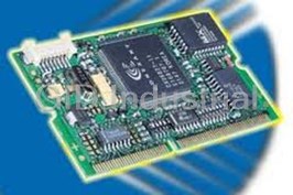
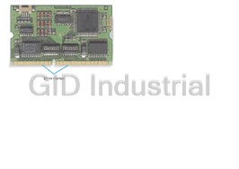
Kontron DIMM-PC/Modem - DIMM-PC Modem Module
Part Number
DIMM-PC/Modem
Price
Request Quote
Manufacturer
KONTRON
Lead Time
Request Quote
Category
PRODUCTS - D
Specifications
Auto dial
DTMF (Touchtoneä), Pulsedial
Command Control
Hayes (AT) commands .
Data format
10 / 11 bit asynchronous
Error correction and data compression
MNP 2-4,V.42 LAPM, MNP10, MNP 10EC
Serial Interface
300...230.400bps, Autobauding
Features
- 5V only power supply.
- Board size : Modem-module 68 x 40 mm (2,68" x 1,57") DAA-module 30 x 50 mm (1,18” x 1,97”)
- Different selectable I/O-Addresses and IRQs
- Low power CMOS technology.
- Signal pinning according DIMM-PC specification
Datasheet

Extracted Text
DIMM-PC/MD
Product Manual
Document Revision 1.0
DIMM-PC/MD Product Manual Content
CONTENTS
1. USER INFORMATION ...................................................................................................1
1.1 ............................................................................................. ABOUT THIS MANUAL 1
1.2 .......................................................................................................... TRADEMARKS 1
1.3 ................................................................................................................. GENERAL 1
1.4 ..............................................................................................................WARRANTY 2
1.5 ...............................................................................................TECHNICAL SUPPORT 3
2. INTRODUCTION ............................................................................................................4
2.1 ..............................................................................KONTRON DIMM-PC-CONCEPT 4
3. FEATURES OF THE DIMM-PC/MODEM ..................................................................6
4. BLOCK DIAGRAMM DIMM-PC/MODEM ................................................................7
5. MECHANICAL SPECIFICATION ...............................................................................8
5.1 ....................................................................................ELECTRICAL SPECIFICATION 11
5.2 ................................................................................PERFORMANCE SPECIFICATION 12
5.3 .......................................................................... ENVIRONMENTAL SPECIFICATIONS 13
6. HARDWARE-INSTALLATION ..................................................................................14
6.1 ...................................................................................................LINE-CONNECTION 14
6.2 ................DEFINITION OF THE HARDWARE-INTERRUPTS AND OF THE I/O-ADDRESS 15
7. SOFTWARE SPECIFICATION...................................................................................16
7.1 ........................................................................................................DIMM-PC/MD 16
7.2 ....................................................................AT COMMANDS REFERENCE MANUAL 17
8. TROUBLESHOOTING.................................................................................................25
9. REVISION HISTORY...................................................................................................25
Kontron® Embedded Modules GmbH i Revision 1.0
DIMM-PC/MD Product Manual User Information
1. USER INFORMATION
1.1 About This Manual
Copyright 2002. Kontron Embedded Modules GmbH.
In this document Kontron Embedded Modules GmbH will also be referred to by the short
form "Kontron".
The information in this document has been carefully reviewed and is believed to be
accurate and reliable. However, no responsibility is taken for inaccuracies. Furthermore,
Kontron reserves the right to make changes to any part of this manual to improve
reliability, function or design. Kontron does not assume liability for any product or circuit
described.
1.2 Trademarks
AT and IBM are trademarks of International Business Machines
XT, AT, PS/2 and Personal System/2 are trademarks of International Business Machines
Corporation.
Microsoft is a registered trademark of Microsoft Corporation.
Intel is a registered trademark of Intel Corporation.
All other products and trademarks mentioned in this manual are trademarks of their
respective owners.
The reproduction, transmission or use of this document or its contents is not permitted
without expressed written authority.
Violators will be liable for damages. All rights created by patent grant or registration of a
utility model or design, are reserved.
Kontron 1996Standards
1.3 General
For the circuits, descriptions and tables indicated no responsibility is taken as far as
patents or other rights of third parties are concerned.
The information in the technical descriptions describes the type of the boards and shall
not be considered as assured characteristics.
Kontron® Embedded Modules GmbH 1 Revision 1.0
DIMM-PC/MD Product Manual User Information
The reproduction, transmission or use of this document or its contents is not permitted
without expressed written authority. Violators will be liable for damages. All rights,
including rights created by patent grant or registration of a utility model or design, are
reserved.
1.4 Warranty
Each board is carefully and thoroughly tested before being shipped. If, however,
problems should occur during the operation, please check your user specific settings of
all boards included in your system. That is often the source of the error. If a board is
defect, it can be sent to your supplier for repair. Please take care of the following steps:
1. The board returned should correspond to the factory default settings since a test is
only possible under these settings.
2. Upon receipt of the board, please be aware that your user specific settings were
changed during the test.
Within the guarantee, the repair is free as long as the guarantee conditions were held. If
no error has been found, you will be charged with the test costs due to the high test
expenditure. Repairs outside of duration of the guarantee will be charged.
This Kontron product is warranted against defects in material and workmanship for our
guaranteed warranty period from the date of shipment. During the warranty period,
Kontron will, at its option, either repair or replace products which prove to be defect.
For warranty service or repair, the product must be returned to a service facility
designated by Kontron.
The foregoing warranty shall not apply to defects resulting from improper or inadequate
maintenance or handling by buyer, unauthorized modification or misuse, operation
outside of the environmental specifications for the product, or improper installation or
maintenance.
Kontron will not be responsible for any defects or damages due to a faulty Kontron
product other than the products supplied by Kontron
Kontron® Embedded Modules GmbH 2 Revision 1.0
DIMM-PC/MD Product Manual User Information
1.5 Technical Support
Technicians and engineers from Kontron and/or its subsidiaries are available for
technical support. We are committed to making our product easy to use and will help you
use our products in your systems.
Before contacting Kontron technical support, please consult our Web site for the latest
product documentation, utilities, and drivers. If the information does not help to solve the
problem, contact us by email or telephone. The table below lists Kontron technical
support contacts and service facilities.
Asia Europe North/South America
®
Kontron Embedded Modules Asia Ltd. Kontron Embedded Modules Kontron
GmbH
5F-1, 341, Sec 4 Brunnwiesenstr. 16 3988 Trust Way
Chung Hsiao E. Road 94469 Deggendorf Hayward, CA 94545
Taipei, Taiwan Germany USA
Tel: +886 2 2751 7192 Tel: +49 (0) 991-37024-0 Tel: 510-732-6900
Fax: +886 2 2772 0314 Fax: +49 (0) 991-37024-104 Fax: 510-732-7655
Support-kem@kontron.com techsupport@adastra.com
Kontron® Embedded Modules GmbH 3 Revision 1.0
DIMM-PC/MD Product Manual Introduction
2. INTRODUCTION
2.1 Kontron DIMM-PC-Concept
It is likely that anyone who deals with micro-controller-development, has already thought
of the application of PC-architecture and considered the PC as the engine for an
application. However, most design engineers will get back to the old 87C51 or a similarly
more or less efficient micro-controller. The reasons why the Embedded PC was not yet
able to push away the micro-controllers from the printed boards, are many.
Embedded PCs are mechanically larger than a solution with a micro-controller.
The hardware of an Embedded PC is much more expensive than the micro-controller
solution.
The power consumption of an Embedded PC is usually higher than the one of a micro-
controller circuit.
A lot of times PCs have to be used with ribbon cables which are a possible cause of error.
Micro-controllers are available with a large number of peripheral functions, the PC,
however only has a standard periphery.
On the other hand there are some serious disadvantages of micro-controller solutions.
The software-development is much more complicated and expensive than under a
standard operating system.
Connection to standard-interfaces such as LANs and modems requires complicated driver
software.
Graphical user interfaces can be realized only by large programming efforts.
The development tools are by far not as powerful as PC-programming systems.
Micro-controllers do by far not have as many different PC-SW development tools
available.
This is why the purchase price is usually considerably higher for micro-controller
development tools.
Ready-made software solutions for standard tasks are only available in a very limited
extent.
The specified reasons are only a few of the more common ones, which are important in
deciding whether to implement a micro-controller or to change to PC-architecture.
Kontron® Embedded Modules GmbH 4 Revision 1.0
DIMM-PC/MD Product Manual Introduction
It is a matter of fact, that these points are not always estimated objectively. Who knows
for sure at the beginning of a project how much programming efforts will have to be
made for realizing the application? In most cases, this can only be rated afterwards which
means, too late. Also the problematic nature/software care within the course of the
product life-span is often ignored.
If the Embedded PC is to be implemented in today's micro-controller applications, the
advantages of the PC-architecture have to prevail, compared to a micro-controller
solution.
With the DIMM-PC, JUMPtec has aimed at the micro-controller market and has
presented a completely new concept for the Embedded PC-solution.
The DIMM-PC solves the problems of size and cabling. The prices have been drastically
reduced thanks to new technical designs, making the solution of using a DIMM-PC
possible for many applications. The driving of peripheral functions was also made easier
by the expansion towards the ISA-bus-standard.
Kontron® Embedded Modules GmbH 5 Revision 1.0
DIMM-PC/MD Product Manual Features of the DIMM-PC/Modem
3. FEATURES OF THE DIMM-PC/MODEM
The DIMM-PC/Modem incorporates following features:
· ? Low power CMOS technology.
· ? 5V only power supply.
· Signal pinning according DIMM-PC specification
· Different selectable I/O-Addresses and IRQs
· ? Board size : Modem-module 68 x 40 mm (2,68" x 1,57")
DAA-module 30 x 50 mm (1,18” x 1,97”)
· support for:
V.21, V.22(1200bps), V.22bis(2400bps),V.23, Bell 103, Bell 212, V.32, V.32bis,
V.34, V.34+, K56flex, V.90, V.92, V.17, V.29, V.27ter and V.21 channel 2
Kontron® Embedded Modules GmbH 6 Revision 1.0
DIMM-PC/MD Product Manual Block Diagramm DIMM-PC/Modem
4. BLOCK DIAGRAMM DIMM-PC/MODEM
The modem may be connected directly to the ISA BUS signals of the DIMM-PC.
PSTN
DIMM-PC BUS
DIMM-PC/
DAA Module DIMM-PC
MODEM (ISA-BUS)
I/O
Kontron® Embedded Modules GmbH 7 Revision 1.0
DIMM-PC/MD Product Manual Mechanical Specification
5. MECHANICAL SPECIFICATION
Pinout of DIMM-PC/Modem
Pin number Signal Pin number Signal
1 SA0 2 GND
3 OSC 4 BATT
5 SA1 6 VCC
7 SA2 8 RI4#
9 MASTER# 10 DCD4#
11 SA3 12 DTR4#
13 BALE 14 DSR4#
15 SD15 16 RTS4#
17 SA4 18 CTS4#
19 TC 20 TXD4 / DO
21 SD14 22 RXD4 / DI
23 SA5 24 RI3#
25 DACK#2 26 DCD3#
27 SD13 28 DTR3#
29 SA6 30 DSR3#
31 IRQ3 32 RTS3#
33 DRQ7 34 CTS3#
35 DACk#7 36 TXD3
37 IRQ4 38 RXD3
39 SA7 40
41 SD12 42
43 IRQ5 44 TXD+
45 SA8 46 TXD-
47 SD11 48 RXD+
49 IRQ6 50 RXD-
51 SA9 52 LNLED
53 SD10 54 LKLED
55 IRQ7 56 GND
top side
57 SA10 58 MD14
59 SD9 60 MD13
KEY
KEY KEY
61 SYSCLK 62 MD12
63 SA11 64
65 SD8 66
1 3 5 55 57 59 61 63 65 139 141 143
67 REF# 68 BLUE
69 SA12 70 GREEN
71 I2DAT 72 RED
73 SA13 74 VCC
75 I2CLK 76 VSYNC
77 SA14 78 GND
79 DRQ0 80 HSYNC
81 SA15 82 FPBACK
83 DACK#0 84 MODUL
85 IRQ14 86 SA16
87 IOR# 88 GND
89 SA17 90 FPVDD
91 IRQ15 92 BLANK#
93 IOW# 94 P17
95 SA18 96 P16
97 IRQ12 98 P15
99 SMEMr# 100 P14
101 SA19 102 P13
103 IRQ11 104 P12
105 SMEMW# 106 P11
107 AEN 108 P10
109 IRQ10 110 P9
111 IOCHRDY 112 P8
113 SBHE# 114 P3
115 SD0 116 P2
117 IOCS16# 118 GND
119 ZWS# 120 P1
121 SD1 122 P0
123 MEMCS16# 124 P7
125 SD2 126 P6
127 SD3 128 P5
129 DRQ2 130 P4
131 SD4 132 VPANEL
133 SD5 134 FPVEE
135 IRQ9 136 VDCLK
137 SD6 138 LLCLK
139 SD7 140 VCC
141 RSTDRV# 142 LFS
Pinout of the western socket on the Modem-Module
Kontron® Embedded Modules GmbH 8 Revision 1.0
DIMM-PC/MD Product Manual Mechanical Specification
Western
Socket
pin description
1 not connected
2 a2
3 La (TIP)
4 Lb (RING)
5 b2
6 not connected
La and Lb are from PSTN. a2 and b2 are feedback for serial connected telephones. In
Germany, Austria, Switzerland, France etc. the telephone can be connected in serial. In
the USA, UK etc. the telephone will be connected in parallel (a2 and b2 will not be used
in this case).
Please check the max. REN-number for parallel connection.
Telephone line cables are not harmonized like ISDN-cables. They are country-depending.
Please use the correct cable.
Kontron® Embedded Modules GmbH 9 Revision 1.0
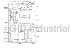
DIMM-PC/MD Product Manual Mechanical Specification
R0.75mm
R2mm
4mm
free area on PCB for further
fixing possibility on applikation
27.5mm
R2.5mm
40mm
18mm
2.5mm
gold plated gold plated
28.25mm
67.6mm
front view
1mm
4mm
2mm
side view
Kontron® Embedded Modules GmbH 10 Revision 1.0
DIMM-PC/MD Product Manual Mechanical Specification
Mechanical Specification of the Modem-DAA-Modul
top view
side view
5.1 Electrical Specification
Supply voltage: 5V DC +/- 5%
Supply voltage ripple: 150mV peak to peak 0 - 20 MHz
Supply current, max: Standby 150 mA
On Line Mode 180 mA
Kontron® Embedded Modules GmbH 11 Revision 1.0
DIMM-PC/MD Product Manual Mechanical Specification
5.2 Performance Specification
ITU Recommendations:
V.21, V.22(1200bps), V.22bis(2400bps),V.23, Bell 103, Bell 212, V.32
V.32bis, V.34, V.34+, K56flex, V.90, V.92
V.17, V.29, V.27ter and V.21 channel 2
Error correction and
data compression: MNP 2-4,V.42 LAPM, MNP10, MNP 10EC
Fax Group 3, Class1, Class1.0.Class2 :
Serial Interface: 300...230.400bps, Autobauding
Data format 10 / 11 bit asynchronous
Command Control Hayes (AT) commands .
Auto dial DTMF (Touchtoneä), Pulsedial
Auto answer
a/b-Interface external Line-Interface (DAA)
Kontron® Embedded Modules GmbH 12 Revision 1.0
DIMM-PC/MD Product Manual Mechanical Specification
5.3 Environmental Specifications
Temperature
operating 0°C - 60 °C see note (*1)
non-operating -40 °C - 85 °C
Thermal gradient
operating 25 °C per hour
non-operating 40 °C per hour
Relative Humidity
operating 10 % - 90 % RH non-condensing
non-operating 5 % - 95 % RH non-condensing
Mechanical
Shock 50G/20ms square wave maximum
Vibration 1G/0-600Hz, dwell not to exceed
Altitude
operating 0 - 3000 m
non-operating 0 - 5000 m
(*1) The maximum operating temperature is the maximum measurable temperature on
any spot on the modules surface. It is the users responsibility to keep this temperature
within the above specification.
Kontron® Embedded Modules GmbH 13 Revision 1.0
DIMM-PC/MD Product Manual Hardware-Installation
6. HARDWARE-INSTALLATION
ATTENTION:
Please FIRST disconnect your DIMM-PC System from any power supply!
The Modem Cards are delivered with settings adjusted to the IRQ5 and to I/O address
3E8h. If those configuration positions are already attributed to other cards, then the
hardware settings for the DIMM-PC/Modem will have to be changed.
6.1 Line-Connection
Please connect the DIMM-PC/Modem with a telephone cable (country depending)to the
PABX or PSTN line
Kontron® Embedded Modules GmbH 14 Revision 1.0
DIMM-PC/MD Product Manual Hardware-Installation
6.2 Definition of the Hardware-Interrupts and of the I/O-Address
The definition of the Hardware-Interrupts and the I/O addresses is performed by means of
the DIP-switches located in the middle of the card ( see the picture below).
The relevant switch positions for the possible I/O Addresses and Hardware-Interrupts are
described in detail in the following table.
S1 S2 S3 S4 Address S1 S2 S3 S4 S2 S5 S6 S7 S8 Interrupt
OFF OFF OFF OFF 2E0 OFF OFF OFF OFF OFF OFF OFF OFF IRQ 3
ON
OFF OFF OFF 2E8 OFF OFF OFF OFF OFF OFF OFF OFF IRQ 4
ON ON
OFF OFF OFF 2F0 OFF OFF OFF OFF OFF OFF OFF OFF IRQ 7
ON ON
OFF OFF 2F8 OFF OFF OFF OFF OFF OFF OFF OFF IRQ 9
ON ON ON
OFF OFF OFF 3E0 OFF OFF OFF OFF OFF OFF OFF OFF IRQ 10
ON ON
OFF OFF OFF OFF OFF OFF OFF OFF OFF OFF IRQ 11
ON ON 3E8 (default) ON
OFF OFF 3F0 OFF OFF OFF OFF OFF OFF OFF OFF IRQ 12
ON ON ON
OFF 3F8 OFF OFF OFF OFF OFF OFF OFF OFF IRQ 15
ON ON ON ON
X X X OFF OFF OFF OFF OFF OFF OFF OFF OFF IRQ 5
ON IRQ 5 (default)
NOTE:
The IRQ and I/O Address of the card should not be used by any other computer
peripheral equipment. If necessary, you should define your own address and IRQ.
Kontron® Embedded Modules GmbH 15 Revision 1.0
DIMM-PC/MD Product Manual Software Specification
7. SOFTWARE SPECIFICATION
7.1 DIMM-PC/MD
For controlling the modem select a suitable COM Port address and IRQ.
The Modem appears at the ISA Bus (DIMM-IO Bus) as device with UART 16550
compliant register set according the specified settings.
The modem will be controlled by AT (Hayes) commands. The baud rate is selectable
from 300...230.400 baud asynchronous. 10 and 11 bit transmission is supported
(including START and STOP bit).
For modem control just use a standard terminal program (TELIX, Procom etc.).
For instance, hyper terminal or similar can be used for Windows based PCs.
The baud rate will automatically set by typing „AT CRLF“. Then the modem will answer
„OK“
The AT command reference is based on the original CONEXANT documentation. The
complete document can be downloaded from our webpage, section “Embedded Internet”.
Since the modem acts as standard serial device, no specific software and operating
system drivers are required. Usually, the modem is directly supported by the operating
system (as “modem with standard hayes command set”).
Kontron® Embedded Modules GmbH 16 Revision 1.0
DIMM-PC/MD Product Manual Software Specification
7.2 AT Commands Reference Manual
NOTE:
Take the section below as short reference to the content of the complete conexant
modem chip manual (which can be downloaded from our web page). Some functions
require additional hardware e.g. speaker control. Some commands for voice and
speakerphone control requires code which is not part of the DIMM-PC/Modem.
These commands are not supported.
Contents of the conexant manual
Figures
1 lntroduction 1-1
1.1 Overview 1-1
1.1.1 Command Syntax 1-1
1.1.2 Command Descriptions 1-1
1.1.3 CaII Progressand Blacklisting Parameters 1-1
1.1.4 ConfigurACE II for Windows Utility Program 1-2
1.2 Reference Documentation 1-2
2 Syntax and Procedures
2.1 Alphabet 2-1
2.2 DTE Commands Lines 2-1
2.2.1 Command Line General Format 2-1
2.2.2 Command Line Editing 2-2
2.2.3 Command Line Echo 2-2
2.2.4 Repeating a Command Line 2-2
2.2.5 Types of DTE Commands 2-2
2.3 Basic Syntax Commands 2-2
2.3.1 Basic Syntax Command Format 2-2
2.3.2 S-Parameters 2-3
2.4 Extended Syntax Commands 2-4
2.4.1 Command Naming Rules 2-4
2.4.2 Values 2-4
Numeric Constants 2-4
String Constants 2-5
Compound Values 2-5
2.4.3 Action Commands 2-5
Action Execution Command Syntax 2-5
Action Test Command Syntax 2-6
2.4.4 Parameter Commands 2-6
Kontron® Embedded Modules GmbH 17 Revision 1.0
DIMM-PC/MD Product Manual Software Specification
Parameter Types 2-6
Parameter Set Command Syntax 2-7
Parameter Read Command Syntax 2-7
Parameter Test Command Syntax2-7
2.4.5 Additional Syntax Rules 2-7
Concatenating Commands after Extended Syntax Commands 2-7
Concatenating Commands after Basic Format Commands 2-8
2.5 Issuing Commands
2.6 Executing Commands
2.6.1 Aborting Commands 2-8
2.6.2 Handling of lnvalid Numbers and S-Parameter Values 2-9
2.7 Modem Responses
2.7.1 Responses 2-9
2.7.2 Extended Syntax Result Codes 2-10
2.7.3 Information Text Formats for Test Commands 2-11
Range of Values 2-11
Compound Range of Values 2-11
3 Data Command Set 3-1
3.1 Command Guidelines 3-1
3.1.1 Escape Code Sequence 3-1
3.2 Data Commands 3-1
3.2.1 Generic Modem Control 3-2
Z - Soft Reset and Restore Profile 3-2
+FCLASS - Select Active Service Class 3-2
+VCID - Caller ID (CID) 3-3
+VRJD - Report Retrieved Caller ID (CID) 3-4
\N - Operating Mode 3-5
I - Identification 3-6
+GMI - Request Manufacturer ldentification 3-7
+GMI9 - Request Conexant ldentification 3-7
+GMM - Request Model ldentification 3-8
+GMR - Request Revision ldentification 3-8
+GCAP - Request Complete Capabilities List 3-8
+GCI - Country of Installation 3-9
&F - Restore Factory Configuration (Profile) 3-10
&T - Local Analog Loopback Test 3-10
&Y - Designate a Default Reset Profile 3-11
&W - Store Current Configuration 3-11
&Zn=x - Store Telephone Number 3-12
%7 - Plug and PIay Serial Number 3-12
%8 - PIug and PIay Vendor ID and Product Number 3-13
** - Load Flash Memory 3-14
3.2.2 DTE-Modem Interface commands 3-16
E - Command Echo 3-16
0 - Ouiet Results Codes Control 3-16
Kontron® Embedded Modules GmbH 18 Revision 1.0
DIMM-PC/MD Product Manual Software Specification
V - Result Code Form 3-17
W - Connect Message Control 3-17
X - Extended Result Codes 3-18
&C - RLSD (DCD) Option 3-23
&D - DTR Option 3-23
&K - Flow Control 3-24
&M - Asynchronous!Synchronous Mode Selection 3-25
&Q - Sync/Async Mode 3-26
&R - RTS/CTS Option 3-27
&S - DSR Override 3-27
&X - Select Synchronous Clock Source 3-28
+IPR - Fixed DIE Rate 3-29
+IFC - DTE-Modem Local FIow Controi 3-30
+ILRR - DTE-Modem Local Rate Reporting 3-31
3.2.3 CaII Control 3-32
D - DiaI 3-32
T - Set Tone DiaI Default 3-35
P - Set Pulse DiaI Default 3-35
A - Answer 3-35
H - Disconnect (Hang-Up) 3-36
O - Return to On-Line Data Mode 3-37
L - Speaker Volume 3-38
M - Speaker Control 3-38
&G - Select Guard Ione 3-39
&P - Select Pulse DiaI Make/Break Ratio 3-39
&V - Display Current Configuration and Stored Profiles 3-40
&V1 - Display Last Connection Statistics 3-41
\V - Single Line Connect Message Enabie 3-42
%L - Report Line Signal Level 3-43
%Q - Report Line Signal Quality 3-43
*B - Display Blacklisted Numbers 3-43
*D - Display Delayed Numbers 3-44
-PPD= - Extension Pickup Notitication through 16550 UARI 3-44
-STE= - Set Telephony Extension 3-45
3.2.4 Modulation Control Commands 3-51
+MS - Modulation Selection 3-51
+MR - Modulation Reporting Control 3-53
%E - Enable/Disable Line Quality 3-55
%U - Select u-Law or A-Law Codec Type 3-56
B - CCITT or Bell 3-56
3.2.5 Error Control Commands 3-57
+ES - Error Controi and Synchronous Mode Selection 3-57
+EB - Break Handiing in Error Control Operation 3-59
+ESR - Selective Repeat 3-59
Kontron® Embedded Modules GmbH 19 Revision 1.0
DIMM-PC/MD Product Manual Software Specification
+EFCS - 32-bit Frame Check Sequence 3-60
+ER - Error Controi Reporting 3-61
+ETBM - CaII Termination Buffer Management 3-63
\B - Transmit Break to Remote 3-64
\K - Break Control 3-65
-K - MNP Extended Services 3-66
3.2.6 Data Compression Commands 3-67
+DS - Data Compression 3-67
+DS44 - V.44 Compression Select 3-68
+DR - Data Compression Reporting 3-69
%C - Enable/Disable Data Compression 3-71
3.2.7 V.8/V.8bis Commands 3-72
+A8E - V.8 and V.8bis Operation Controls 3-72
+A8I: - CI Signal lndication 3-73
3.2.8 Synchronous Access Mode Commands 3-74
+ESA - Configure Synchronous Access Submode 3-74
+H - Enable/Disable RPI 3-76
+ITF - Transmit Flow Control Thresholds 3-77
3.2.9 Diagnostic Commands 3-78
#DU - Last CaIl Status Report 3-78
3.2.10 Compatibility Commands 3-86
&L - Leased Line Operation 3-86
)M - Enable Cellular Power Level Adjustment 3-86
@M - lnitial CelIular Power Level Setting 3-87
:E - Compromise Equalizer Enable Command 3-87
3.2.11 FastConnect Commands 3-88
$F - FastConnect Control 3-88
3.2.12 V.92 +P and -Q Commands 3-89
+PCW - CaIl Waiting Enable 3-89
+PMH - Modem-on-Hold Enable 3-90
+PMHT - Modem-on-Hold Timer 3-91
+PMHR - lnitiate Modem-on-HoId 3-92
+PIG - PCM Upstream lgnore 3-93
+PMHF - V.92 Modem-on-HoId Hook Flash 3-93
+PQC - V.92 Phase 1 and Phase 2 Control 3-94
+PSS - Use Short Sequence 3-95
-QCPC - Force Full Startup Procedure Next Connection 3-96
-QCPS - Enable Quick Connect Profile Save 3-96
3.3 S-Parameters 3-97
S - Read/Write S-Parameter 3-97
3.3.1 FACTORY DEFAULTS 3-97
3.3.2 S-PARAMETER DEFINITIONS 3-99
S0 - Number of Rings to Auto-Answer 3-99
S1 - Ring Counter 3-99
S2 - Escape Character 3-99
S3 - Carriage Return Character 3-99
S4 - Line Feed Character 3-99
Kontron® Embedded Modules GmbH 20 Revision 1.0
DIMM-PC/MD Product Manual Software Specification
S5 - Backspace Character 3-100
S6 - Wait Time before Blind Dialing or for Dial Tone 3-100
S7 – Wait Time for Carrier, Silence, or Dial Tone 3-100
S8 - Pause Time For Dial Delay 3-101
S9 - Carrier Detect Response Time 3-101
S10 - Lost CarrierTo Hang Up Delay 3-101
S11 - DTMF Tone Duration 3-101
S12 - Escape Prompt Delay (EPD) 3-102
S14 - General Bit Mapped Options Status 3-102
S16 - Test Mode Bit Mapped Options Status 3-102
S19 - Reserved 3-103
S20 - Reserved 3-103
S21 - V.24/General Bit Mapped Options Status 3-103
S22 - Speaker/Results Bit Mapped Options Status 3-104
S23 - General Bit Mapped Options Status 3-104
S24 - Sleep lnactivitylimer 3-104
S25 - Delay To DIR 0ff 3-105
S26 - RTS to CTS Delay 3-105
S27 - Bit Mapped Options Status 3-105
S28 - Bit Mapped Options Status 3-106
S29 - Flash Dial Modifierlime 3-106
S30 - Disconnect lnactivity Timer 3-106
S31 - Bit Mapped Options Status 3-107
S36 - LAPM Failure Control 3-107
S38 - Delay Before Forced Hang Up 3-108
S39 - Flow Control Bit Mapped Options Status 3-108
S40 - General Bit Mapped Options Status 3-108
S41 - General Bit Mapped Options Status 3-109
S46 - Data Compression Control 3-109
S48 - V.42 Negotiation Control 3-109
S86 - Call Failure Reason Code 3-110
S91 - PSTN Transmit Attenuation Level 3-111
S92 - Fax Iransmit Attenuation Level 3-111
S95 - Extended Result Codes Control 3-111
S210 - V.34 Symbol Rates 3-112
3.4 Cellular Commands 3-113
3.4.1 Cellular Phone Drivers 3-113
3.4.2 CelluLar Commands 3-113
^C2 - Download CelIular Phone Driver 3-113
^I - Identity Cellular Phone Driver 3-114
^T6 - lndicate Status of Cellular Phone 3-114
3.4.3 Operation 3-115
Modem Configuration 3-115
Fax Configuration 3-116
Cellular Phone Configuration 3-116
3.5 Result Codes 3-118
Kontron® Embedded Modules GmbH 21 Revision 1.0
DIMM-PC/MD Product Manual Software Specification
4 Fax Class 1 and Fax Class 1.0 Commands 4-1
4.1 Fax I/O Processing 4-1
4.1.1 DTE-to-Modem Iransmit Data Stream 4-1
4.1.2 Modem-to-DTE Receive Data Stream 4-1
4.1.3 Fax Mode Selection 4-1
4.1.4 Fax Origination 4-3
4.1.5 Fax Answering 4-3
4.1.6 Fax Control Transmission 4-3
4.1.7 Fax Control Reception 4-3
4.1.8 Fax Data Transmission 4-4
4.1.9 Fax Data Reception 4-5
4.2 Commands and Parameters 4-6
4.2.1 Mode Entry Commands 4-6
+FCLASS=1 - Select Facsimile Class 1 Mode 4-6
+FCLASS=1.0 - Select Facsimile Class 1.0 Mode 4-6
4.2.2 Mode Commands 4-6
+FAA - Auto Answer Enable 4-6
+FAE - Auto Answer Enable 4-7
+FTS - Transmit Silence 4-7
+FRS - Receive Silence 4-8
+FTM - Transmit Facsimile 4-9
+FRM - Receive Facsimile 4-10
+FTH - Transmit Data with HDLC Framing 4-11
+FRH - Receive Datawith HDLC Framing 4-12
4.2.3 Service Class 1 Parameters 4-13
+FAR - Adaptive Reception Control 4-13
+FCL - Carrier Loss Timeout 4-14
+FDD - Double Escape Character Replacement 4-15
+FIT - DIE lnactivity Timeout 4-16
+FPR - Fixed DIE Rate 4-17
+FMI? - Request Manufacturer ldentification 4-18
+FMM? - Request Model ldentification 4-18
+FMR? - Request Revision ldentification 4-18
+FLO - Flow Control 4-19
4.3 Examples 4-19
5 Fax Class 2 Commands 5-1
5.1 Command and Syntax Guidelines 5-2
5.1.1 Mode Entry Commands 5-2
+FCLASS=2 - Select Facsimile Class 2 Mode 5-2
5.1.2 DTE Commands 5-2
DTE Command Lines 5-2
Facsimile Command Syntax 5-2
5.1.3 Serial Port Speed and Flow Control 5-4
Kontron® Embedded Modules GmbH 22 Revision 1.0
DIMM-PC/MD Product Manual Software Specification
Data Stream Termination 5-4
DIE to DCE Streams 5-4
DCE to DIE Streams 5-4
5.1.4 Auto Answer 5-4
5.1.5 ldentification of T.30 Options 5-5
5.1.6 Session Status Reporting 5-5
5.1.7 Procedure Interrupt Negotiation 5-5
5.2 Service Class 2 Identification and Selection 5-5
5.2.1 +FMFR? - Request Manufacturer Identification 5-5
5.2.2 +FMDL? - Identify Product Model 5-5
5.2.3 +FREV? - ldentify Product Revision 5-6
5.3 Service Class 2 Action Commands 5-6
5.3.1 ATD - Originate a CaII 5-6
5.3.2 ATA - Answer a CaII 5-7
ManualCalI Answer
Auto matic Answer 5-7
Connection as a Data Modem 5-7
5.3.3 +FDT - Data Transmission 5-7
Initiate Page Transmission 5-8
Continue a Page 5-8
Phase C Data Framing 5-8
Phase C Data Format 5-8
Frequently asked questions
What makes Elite.Parts unique?

What kind of warranty will the DIMM-PC/Modem have?
Which carriers does Elite.Parts work with?
Will Elite.Parts sell to me even though I live outside the USA?
I have a preferred payment method. Will Elite.Parts accept it?
Why buy from GID?

Quality
We are industry veterans who take pride in our work

Protection
Avoid the dangers of risky trading in the gray market

Access
Our network of suppliers is ready and at your disposal

Savings
Maintain legacy systems to prevent costly downtime

Speed
Time is of the essence, and we are respectful of yours
Related Products
Kontron DIMM-PC/386 - DIMM-PC 386SX CPU Module
Kontron DIMM-PC/486-I - Motherboard with 80486 SX CPU, 4/16 MByte DRAM, keyboard controller, real ti...
Kontron DIMM-PC/ADA3 - Backplane / Starter Kit / Evaluation Board for DIMM-PC Series CPU Modules
Kontron DIMM-PC/ISDN - ISDN expansion Module
Request a Quote

The quote request has been received
Close

Facing challenges or have inquiries? Feel free to contact us!
Call Us +1-469-283-2440
What they say about us
FANTASTIC RESOURCE
One of our top priorities is maintaining our business with precision, and we are constantly looking for affiliates that can help us achieve our goal. With the aid of GID Industrial, our obsolete product management has never been more efficient. They have been a great resource to our company, and have quickly become a go-to supplier on our list!
Bucher Emhart Glass
EXCELLENT SERVICE
With our strict fundamentals and high expectations, we were surprised when we came across GID Industrial and their competitive pricing. When we approached them with our issue, they were incredibly confident in being able to provide us with a seamless solution at the best price for us. GID Industrial quickly understood our needs and provided us with excellent service, as well as fully tested product to ensure what we received would be the right fit for our company.
Fuji
HARD TO FIND A BETTER PROVIDER
Our company provides services to aid in the manufacture of technological products, such as semiconductors and flat panel displays, and often searching for distributors of obsolete product we require can waste time and money. Finding GID Industrial proved to be a great asset to our company, with cost effective solutions and superior knowledge on all of their materials, it’d be hard to find a better provider of obsolete or hard to find products.
Applied Materials
CONSISTENTLY DELIVERS QUALITY SOLUTIONS
Over the years, the equipment used in our company becomes discontinued, but they’re still of great use to us and our customers. Once these products are no longer available through the manufacturer, finding a reliable, quick supplier is a necessity, and luckily for us, GID Industrial has provided the most trustworthy, quality solutions to our obsolete component needs.
Nidec Vamco
TERRIFIC RESOURCE
This company has been a terrific help to us (I work for Trican Well Service) in sourcing the Micron Ram Memory we needed for our Siemens computers. Great service! And great pricing! I know when the product is shipping and when it will arrive, all the way through the ordering process.
Trican Well Service
GO TO SOURCE
When I can't find an obsolete part, I first call GID and they'll come up with my parts every time. Great customer service and follow up as well. Scott emails me from time to time to touch base and see if we're having trouble finding something.....which is often with our 25 yr old equipment.
ConAgra Foods