

 Manufacturers
GESPAC GESSBS-8

Description
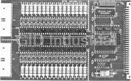
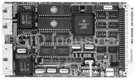
GESPAC GESSBS-8 CPU Board. General Purpose Single Board System, 16-bit computer system on the G-96 Bus.
Part Number
GESSBS-8
Price
Request Quote
Manufacturer
GESPAC
Lead Time
Request Quote
Category
PRODUCTS - G
Features
- 1 DMA channel available on the external connector (coupled with the 82C55)
- 256 Kbytes of CMOS static RAM protected against power-failure
- 8OC186-16 microprocessor (16 Mhz)
- Fully compatible with the G-96 Standard Bus
- Internal 1/0 processor (timers and interrupt controller)
- Optional numeric coprocessor 8OC1 87-16 (16 Mhz)
- Real-time Clock/Calendar with 51 bits of SRAM and on-board battery backup
- Standard power supply: +5 V, +12 V, -12 V
- Three 16-bit counters/timers (82C54)
- Three 8-bit bidirectionnal 1/0 ports (82055)
- Total addressing capability up to 1 Mbyte
- Two independent synchronous/asynchronous Serial Channels (85C30)
- Two interrupt controllers allowing 5 auto-vectored interrupts on the G-96 Bus
- Up to 512 Kbytes of SRAM and 256 Kbytes of EPROM or up to 256 Kbytes of SRAM and 512 Kbytes of EPROM
Datasheet

Extracted Text
8OC186 SINGLE BOARD SYSTEM The GESSBS-8 Single Board System is a general purpose, 16-bit computer system on the G-96 Bus. This state-of-the-art product offers unique features in a single Eurocard format. Designed around the powerful 80CI 86 processor running at 16 Mhz, this module has 256 Kbytes of zero wait-state CMOS RAM. Four 32-pin JEDEC sockets support up to 512 Kbytes of EPROM or 256 Kbytes of EPROM plus 256 Kbytes of SRAM. The unused memory area is available on the G-96 Bus in the VMA field and allows system memory extension. All basic 1/0 such as timers, RS-232, interrrupt controllers, Real-time Clock/Calendar, and parallel 1/0 are implemented on-board providing a complete system suited to most embedded applications. Additionally, an 80C187 coprocessor can be added for high performance numerics processing. Technical features · 8OC186-16 microprocessor (16 Mhz) · 256 Kbytes of CMOS static RAM protected against power-failure · Up to 512 Kbytes of SRAM and 256 Kbytes of EPROM or up to 256 Kbytes of SRAM and 512 Kbytes of EPROM · Total addressing capability up to 1 Mbyte · Two independent synchronous/asynchronous Serial Channels (85C30) · Three 16-bit counters/timers (82C54) · Three 8-bit bidirectionnal 1/0 ports (82055) · Optional numeric coprocessor 8OC1 87-16 (16 Mhz) · 1 DMA channel available on the external connector (coupled with the 82C55) · Real-time Clock/Calendar with 51 bits of SRAM and on-board battery backup · Two interrupt controllers allowing 5 auto-vectored interrupts on the G-96 Bus · Internal 1/0 processor (timers and interrupt controller) · Fully compatible with the G-96 Standard Bus · Standard power supply: +5 V, +12 V, -12 V m References GESSBS-8/256: High performance 8OC186 single board system (1 6 bits) with 256 K SRAM (TTL version) GESSBS-8U256: High performance 8OC186 single board system (1 6 bits) with 256 K SRAM (CMOS version) GESSBS-8F/256: Idem GESSBS-8 with BOC187-16 Numeric Processor GESSBS-8LF/256: ldem GESSBS-8L with 80C187-16 Numeric Processor GESPAC SA. 1990 1.2 SPECIFICATION 1. GENERAL INFORMATION 16 Mhz CPU Clock 1.1 DESCRIPTION Addressing capability Using surface mount devices on both sides and state-of-the- art Internal memory: PCB technology, GESPAC offers a complete 8OC186 system in single Eurocard format. Designed around the advanced, high TOP EPROM: I From 8 Kbytes to 256 Kbytes integration 80CI 86 microprocessor running at 16Mhz, the (two 271 001) GESSBS-8 board is upward compatible with 8086, 8088, and 0 - 3 programmable wait-states 80286 software. When equipped with the numeric processor LOW RAM 256 Kbytes of CMOS static RAM extension (80CI 87-16), the GESSBS-8 module provides a solution 0 wait-state for GESSBS-8 for high performance numerics processing. The 8OC187 is upward 1 wait-state for GESSBS-8L object-code compatible with the 8087 numeric coprocessor and MEDIUM MEMORY From 16 Kbytes completely object- code compatible with the 80387 numeric to 256 Kbytes RAM or EPROM coprocessor. 0 - 3 programmable wait-states External Memory From 256 Kbytes to 512 Kbytes The GESSBS-8 module has 256 Kbytes of CMOS RAM with zero (On-board memory dependent) External peripherals wait-state. A power-failure logic circuit with an external battery I K x 16 Asynchronous provides data integrity in static RAM. Four 32-pin JEDEC sockets 1 K x 16 Synchronous support up to 512 Kbytes of EPROM or 256 Kbytes of EPROM plus 256 Kbytes of static RAM. The EPROM/RAM extension can Internal peripherals: operate from zero to three wait- states. The unused memory area Coprocessor: Optional 8OC1 37-16 (16 Mhz) Serial can be addressed on the G-96 Bus allowing full I Mbyte 80CI 86 controller: Two RS-232 type or synchronous, addressing capability. SDLC,HDLC Baud Rate: Software programmable to The GESSBS-8 module includes a dual-channel Serial 38,4 Kbits/s in RS-232 Communication Controller (SCC 85C30). The SCC can be (quartz = 4,9152 Mhz) software-configured to satisfy a variety of serial communication Timers: Three independent 16-bit applications, and includes on-chip baud rate generators. These counters/timers (8254) and three serial channels can be configured as DCE and DTE connection to internal 80186 16-bit timers allow downloading, uploading or other useful functions. The board Parallel 1/0: 24 general purpose 1/0 pins (8255) contains three 16-bit timers providing many functions typically Real Time Clock: Year, month, day, hours, minutes, required for multitasking systems such as real-time clock function, seconds, periodic interrupts, alarm measurement of elapsed time or events counting. A CMOS Real- and 51 bits of non-volatile RAM time Clock/Calendar with on-board battery backup gives complete time information (year, month, day, h, m, s), multiple RTC Two external interrupt controllers Interrupts: interrupts and additionally, 51-bits of RAM which can be used for Handles internal interrupts Master: storing the system configuration. Handles five G-96 interrupt lines Slave: Slave mode wired on the master - 80186 int. controller Address bus: Bus Interface: tri-state TTL compatible The module includes a 82C55 general purpose program- - Data bus: mable 1/0 device. It provides 24 1/0 pins which may be tri-state TTL compatible -Other programmed in two groups of twelve, used in three major signals: TTL compatible 8- or modes of operation (input, Output or bidirectional bus with handshaking). 16-bit Sync/Asynchronous Bus Data Transfer: The GESSBS-8 board was designed to provide a powerful Power requirements. + 5 V / 1.7 A typ. (TTL version) interrupt structure to increase efficiency and versatility (i.e, (GESSBS-8/256) +1 2 V / 20 mA typ. (TTL version) -1 iRMX86 mode interrupt structure). A master interrupt controller (TTL Version) 2 V / 20 mA typ. (TTL version) manages the internal interrupt sources; a slave interrupt controller manages five auto-vectored interrupts through the G-96 Bus. The Power requirements + 5 V / 0.320 A typ. 8OC186 NMI line can be routed on the G-96 Bus PWF or NMI line, (GESSBS-8U256) +1 2 V / 20 mA typ. or time-out logic in the case of addressing an asynchronous area (CMOS Version) -1 2 V / 20 mA typ. not present on the bus. Operating temp.: PCB + 5' to +55' C (TTL version) dimension: 100 x 160 mm The GESSBS-8 module is fully compatible with the G-96 Bus as described in the GESPAC G-64IG-96 Bus Specification Manual Table 1.1 Specifications and can be used with all asynchronous or synchronous G-64/G-96 1/0 modules. The block diagram in Figure 1.1 illustrates the different module parts. 1.3 MEMORY MAP The GESSBS-8 was designed to provide maximum internal addressing capability minimizing the access time during memory cycles. The 80186 CPU includes integrated chip selection logic used to enable memory devices. Memory chip selection lines are split into three groups that separately address major memory areas. Only two chip selection lines are used inside the GESSBS-8 module: UCS upper memory for resetting ROM and LCS lower memory chip selection for system RAM. Other memory areas (internal RAM/EPROM extension and VMA signal) are hardware decoded. The UCS and LCS area sizes are programmable. Starting and ending locations of lower and upper memory are fixed at OOOOOH and OFFFFFH, respectively. The starting location of mid-range memory (internal RAM/EPROM extension) is programmable via a set of jumpers. Each programmed chip selection area has a set of associated programmable ready bits. These readybitscontrolthe8OCl 86 integrated wait-state generator. Table 1.3 Memory Map This allows a programmable number of wait-states (O - 3) to be automatically inserted whenever an access to a particular chip Four 2764 EPROM located at the top memory area allowing: 32 selection area is made. LCS size is fixed at 256 Kbytes and the Kbytes of EPROM, 256 Kbytes of internal SRAM and 736 Kbytes UCS size is dependent on the user installed EPROM. Table 1.2 of G-96 VMA area. shows the GESSBS-8 standard memory map and Tables 1.3, 1.4 and 1.5 show examples using the internal extension memory sockets with different EPROM/RAM sizes. Refer to Section 4 for EPROM/RAM wait-state considerations. 512 Kbytes of SRAM located at the bottom memory area and 256 Kbytes of EPROM located at the top memory area plus, 256 Kbytes of G-96 VMA area. Table 1.5 Memory Map 512 Kbytes of contiguous EPROM located at the top of the Table 1.6 Internal 1/0 Map memory area, 256Kbytesof internal SRAM plus 256 Kbytes of G- 96 VMA area. 1.4.2 EXTERNAL I/0 - VPA FIELD 1.4 1/0 MAP The external I/O field is divided in two banks of 2 Kbytes each, The 8OC186 CPU supports both 8- and 16-bit I/O devices. The allowing interfacing of the GESSBS-8 with synchronous and CPU reserves a 64 Kbyte segment for 1/0. Four special 1/0 asynchronous I/0 modules. The external 1/0 field is characterized instructions are available for these communications. The on the G-96 Bus by the VPA signal and the AO-A9 address lines GESSBS-8 module uses this special scheme for addressing the (corresponding to Al -Al O of the 8OC186's physical address on-board peripheral devices and generating the VPA signal when lines). If the 1/0 module is an 8-bit module, it is connected on accessing peripheral devices on the G-96 Bus. DO-D7 lines of the G-96 Bus (corresponding to D8-DI 5 of the 80CI 86's data lines) and is always addressed with ODD addresses. 1.4.1 INTERNAL 1/0 ADDRESSES Due to the redundancy of the two fields, only two Kbytes are available for connecting 1/0 devices. This means that if The GESSBS-8 includes seven internal 1/0 devices: 8530 SCC, an asynchronous device is placed at address FOOOH, it is two 82C59 Interrupt Controllers, 82C54 Timer, 8OC1 87 not possible to have a synchronous module connected at Coprocessor, 7170 Real-Time Clock/Calendar, and the 82C55 address F800H. These CPU addresses relate to the same parallel 1/0 controller. All these devices are connected on data physical address on the bus. Mapping of the VPA field is shown in Table 1.7. lines DO-07 of the 8OC186 CPU, with only even addresses allowed. The 8OC1 86 generates chip selections for up to seven peripheral devices. The GESSBS-8 module uses the first five chip selection lines (Peripheral Chip Selects PCSO to PCS4) to decode the internal 1/0. These chip selections are active for five contiguous blocks of 128 bytes, above a programmable base address. This base address is located in 1/0 space and must be a multiple of 1 Kbyte. PCS5 and PCS6 are programmed to provide latched address bits Al and A2. GESSBS-8 internal device base addresses are shown in Table 1.6. Refer to Section 4 for wait-state generation and base address selection. WARNING: Do not attempt to reference other 1/0 addresses due to the risk of stopping the system indefinitely Table 1.7 VPA field addresses 1.6 TIMER 1.5 82C59 INTERRUPT CONTROLLERS The 82C54 has three independent programmable 16-bit counters, The GESSBS-8 includes two 82C59 Priority Interrupt controller each capable of handling clock input frequencies of up to 10 Mhz. chips. The Master device handles interrupts from internal All I/0 signals of the three timers are available on a connector peripherals, and manages the cascade mode for the slave interrupt allowing the 82C54 to be used as an event counter, elapsed time controller and the 8OC186 integrated interrupt controller. This indicator, programmable one-shot, along with many other Master Interrupt Controller must be programmed to operate in the applications. The OUT0, OUT1 or OUT2 outputs can be routed to edge sensitive interrupt mode. The Slave interrupt controller the master interrupt line IRQ0 via a jumper. For more information receives only the five G-96 interrupts lines. These external interrupts must be programmed as slave devices to allow the auto- about programming, refer to the Intel Data Book. Table 1. IO shows vectored mode on the G-96 bus. The 82C59 device must be the Timer register addresses. programmed as a slave and operates in the level interrupt mode. Tables 1.8 and 1.9 show the assignment of 82C59 interrupt inputs. Tablel.10 Timer 82C54 register map * Slave input means the device connected on this input 1.7 REAL-TIME CLOCK/CALENDAR - ICM 7170 generates its own vector during INTA cycle. Non-Slave input means the device connected on this input The ICM 7170 chip gives the GESSBS-8 board a real-time cannot generate vectors. clock/calendar functioning from 1/100s to years, and two interrupt Table 1.8 Master device interrupt structure functions. First is the periodic interrupt (i.e., 100HZ, 10Hz, etc.) which can be programmed by the internal interrupt control register to provide seven different output signals. Second type is the alarm interrupt. The alarm time is set by loading a 51-bit RAM that activates an interrupt output through a comparator. This 51-bit RAM can otherwise be used to save the system configuration during power shut-down. Tables 1.1 1 through 1.1 5 show the ICM 7170 register map. All G-96 Interrupt lines work in the auto-vectored mode. The Slave controller must be programmed to generate the vector during an INTA cycle. Table 1.9 Slave device interrupt structure Tablel.15 Command Register Bit Assignment 1.8 80187 NUMERIC PROCESSOR EXTENSION The 8OC187 numeric processor extension is optional and supported by the GESBS-8 hardware. Updating the system is Table l.11 Address codes and functions accomplished by installing the 8OC187 in its socket and removing a jumper. When the 8OC186 executes an ESC instruction, the CPU automatically generates one or more I/0 operations to the 8OC187's reserved I/0 addresses (F8H, FAH, FCH). These I/0 operations take place independently of the 8OC186's current I/0 privilege level. Reserved I/0 addresses are generated Table l.12 lnterrupt Mask Register (write only) automatically by the processor. These I/0 addresses should not be referenced explicitly, due to the risk of corrupting data within the SOC187. Tablel.13 lnterrupt Status Register(read only) Table l.14 Command Register Format 1.9.2 8530 REGISTERS 1.9 SERIALCOMMUNICATIONSCONTROLLER The 8530 SCC contains 13 registers per channel allowing 1.9.1 GENERAL DESCRIPTION configuration of that channel's functional characteristic. Six registers are directly accessible by the CPU allowing access The 8530 SCC Serial Communications Controller is designed for of the other 8530 registers as shown in Table 1. 1 7. multi-f unction support in order to handling the large variety of serial communication protocols available. The 8530 can be programmed to satisfy special serial communications requirements Physical Access Register name address as well as to follow standard formats such as byte-oriented synchronous, bit-oriented synchronous and asynchronous. The features of the 8530 SCC are listed in Table 1. 1 6. 0100H Channel B Control Register R 0100H Channel B Status Register W Channel B Data Register 0102H R/W Channel A Control Register 0104H Two independent full-duplex channels W Channel A Status Register 0104H Receiver data registers qua-duplex buffered R 0106H Channel A Data Register R/W Transmitter data registers double buffered Baud Rate generator in each channel Tablel.17 8530 SCC direct access register map Digital Phase-Locked Loop for clock recovery NRZ, NRZI and FM encoding/decoding Notes: - Control Register is the WRO 8530 register Asynchronous capabilities - Status Register is the RRO 8530 register - Data Register, in write access, is the WR8 8530 register - Data Register, in read access, is the RR8 8530 register - 5, 6, 7 or 8 bits per character Baud rate generator has a 4.9152 Mhz input frequency 1, 1-1 /2 or 2 stop bit Odd or Even Parity For more information about programming the 8530 SCC, refer to Times 1, 16, 32 or 64 clock modes the Ziloq Data Book. Break generation and detection Parity, Overrun and framing error detection 1.9.3 8530 INTERRUPT Byte-oriented synchronous capabilities The 8530 SCC can generate a vectored interrupt when one of the Internal character synchronization following conditions occurs: 1 or 2 sync. characters in separate registers Automatic synchronous character insertion and deletion · Channel A transmitter empty Cyclic redundancy check (CRC) generation/detection · Channel A receiver full 6 or 8-bit synchronous character · Channel A external/status condition · Channel B transmitter empty SDLC/H DLC capabilities · Channel B receiver full · Channel B external/status condition Abort sequence generation and checking Automatic zero insertion and deletion Channel A interrupts have a higher priority than Channel B Automatic flag insertion between messages interrupts, with the receiver, transmitter and external/status Address field recognition interrupts prioritized in that order, within each channel. The 8530 1-field residue handling SCC can generate multiple vectors during INTA cycles, and the CRC generation/deletion Master 82C59 Interrupt level can be programmed in a slave mode. SDLC loop mode with EOP recognition/loop Entry and exit Tablel.16 8530 SCC features 2. PREPARATION FOR USE, 1.10 PARALLEL I/O CONTROLLER INTERCONNECTIONS The 82C55 is a programmable peripheral interface (PPI) device. It 2.1 CONNECTOR AND JUMPER IDENTIFICATION is a general purpose I/0 component used to inter- face peripheral equipment to the microcomputer system. The 82C55 device contains three 8-bit ports (A, B and C). All can be configured by Table 2.1 identifies the jumpers and connectors of the GESSBS-8 module. Figure 2.1 shows their locations on the the system software with a variety of functional characteristics. printed circuit. Port A One 8-bit data latch/buffer and one 8-bit data input latch. Designation Function Port B One 8-bit data input/output latch/buffer and one 8-bit data input buffer. G-96 Bus interface connector Pi Port C One 8-bitdataoutputiatch/bufferand one 8-bitdata input External I/0 connector (Serials and P2 buffer (no latch for input). This port can be divided into two 4-bit ports under mode control. Each 4-bit port Parallel I/0) contains a 4-bit latch and can be used for control signal Timer I/0 interface connector P3 outputs and status signal inputs, in conjunction with External reset connector P4 ports A and S. Modem/Terminal selector channel A J1 For more information about programming, refer to the Intel Clock selector for serial port A J2 Data Book. Table 1.1 8 82C55 device address register. Modem/Terminal selector channel B J3 Clock selector for serial port B J4 External I/0 interrupt selection J5 Base Address Access Operation or Register Timer: CLKI input clock selection J6 80H U23 socket EPROM/RAM selection Read/Write PORT A J7 Read/Write Timer: CLK2 input clock selection 82H Read/Write PORT B J8, J9 Read/Write Master IRQO Interrupt selection J10 84H Read/Write Read/Write PORT C Timer: CLKO input clock selection Write J11 86H Write Control Register U25 socket EPROM/RAM selection J12 Numeric Processor Extension J13 Table 1.18 82C55 register map U23/U25 EPROM/RAM size selection J14 / Jl5 U24/U26 EPROM size selection J16 / Jl7 8OC186 NMI source selection Jl8, J21 U23/U25 base address selection 1.11 RESET OPERATION J20,J22-J25 U23/U25 wait states selection J19,J26 The RESET signal is an output to the G-96 bus generated by the E, SYSCLK Tri-State selection J27 GESSBS-8 module during power-on or when an external reset button is pressed. The reset circuitry includes the MAX 691 device Connectors and jumpers identification Table 2.1 which automatically generates a reset during a power-on or power- off (V typ 4.75 V). It is very important to have an appropriate +5 Volts power supply. Figure2.lb Implementation solder side 2.2 RESTART OPERATION 2.3.2 DCE/DTECONFIGURATION Signals defined in Table 2.2 are connected to P2 through the J1 An external switch for system resetting can be connected to and J3 jumpers as illustrated in Figure 2.3. Figures 2.4 and 2.5 the P4 connector as illustrated in Figure 2.2. show the configuration of J1/J3 for two standard applications. For special configurations, refer to Table 2.2 for signal definitions and Figure 2.3 for their interconnection. P4 pin assignment P4 external connection Figure 2.2 External Reset connector 2.3 SERIAL COMMUNICATION INTERFACE 2.3.1 GENERAL INFORMATION The GESSBS-8 provides two serial interfaces driven by the 85C30 SCC device. These two serial interfaces allow asynchronous and synchronous communications, and provide signals for modem connections. Interconnections on J1 and J3 provide the configuration of channels A and B as DCE (Data Communication Equipment) or DTE (Data Terminal Equipment) mode. External I/0 is available through the P2 connector. A 60-wire flat cable is needed to provide the two serial channel and the parallel I/0 interfaces. This flat cable can be connected to a general purpose dispatcher or proprietary design (e.g., opto-coupled I/0, etc.). The GESSBS-8 module uses the GESPAC standard 10-pin RS-232-C pinout for each channel. Standard signals for the RS- 232-C serial interface and the serial channel pin assignments of P2 are shown in Table 2.2. 2.3.3 Tx AND Rx CLOCK SELECTION The transmit and receive clock for channels A and B can be selected to be internal or external for synchronous transfer. When internal, the clocks are provided by the on-chip baud rate generator. Clock selection for channels A and B is done with jumper J2/J4 as shown in Figure 2.6. Figure 2.8 CLK1 clock input selection Figure 2.9 CLK2 clock input selection Figure 2.6 J2/J4 pin assignment: Tx C and Rx C clock selection for channel A and B 2.4 82C54-TIMER CLOCK SELECTION Input clocks of counters O, land 2 can be selected by jumper J11 to provide a basic clock of 1, 2, 4 or 8 Mhz. Other combinations between J11, CLK, OUT, GATE and the external P3 connector are selectable with jumpers J6, J8 and J9. Figure 2.7 shows the basic clock provided by jumper J11 and Figures 2.8 and 2.9 show the different connection possibilities between CLK, OUT, GATE. Figure 2.10 shows the pin configuration of connector P3. Figure 2.10 P3 pin assignment 2.5 TOP EPROM TYPE SELECTION U24 and U26 sockets can be equipped with either 28 or 32-pin JEDEC compatible devices. These sockets can support EPROM devices from 8 Kbytes up to 128 Kbytes (2764, 27128, 27256, 27512, 271001). A28-pin device must be inserted at the bottom of the 32-pin socket provided on the GESSBS-8 module. The U24 socket is connected to upper data (D8-D15) and socket U26 to lower data (DO-D7). Device type selection is made with J16 and J17 jumpers as illustrated in Table 2.3. 2.6 LOW RAM ACCESS TIME The GESSBS-8 module is factory equipped with 256 Kbytes of SRAM, with an access time of 100 ns maximum for the TTL version and 150 ns maximum for the CMOS version. The 8OC1 86 provides a chip selection for low memory called LCS. The lower memory limit defined by this chip selection is always OH, while the upper limit is programmable. The size of this memory block is defined by programming the RAM upper limit in the LMCS Register. The corresponding upper limit of 256 Kbytes is 3F FFFH. The LMCS Register bits 0 - 2 are used to specify the READY mode for the RAM area. Refer to the Intel 8OC186DataSheetorthe IntelAP-186for more information on programming. Refer to Table 2.5 when programming the LMCS Ready bits with 0 wait-state for the TTL version and 1 wait-state for the CMOS version. Table 2.3 EPROM size selection * All other combinations are forbidden **Time from address= 2xCLK + 0.5xCLK - TDVCL - TCHLL - PD374 + (NXCLK) 2.5.1 TOP EPROM ACCESS TIME where: CLK = Clock period of processor Since EPROMs are decoded with the UCS chip selection, the TDVCL = 186 data valid setup time EPROM size and number of wait-states needed to access these TCHLL = ALE inactive delay EPROMs are software programmable, via the 80CI 86 UMCS PD374 = 74 ACT374 propagation delay CP to On Register. Table 2.4 gives the corresponding EPROM access time N = Number of wait-states inserted and number of wait-states to program in the UMCS Register. Note that external ready is ignored during UMCS activity must always Table 2.5 Low SRAM ready bits be specified. Refer to the 8OC186 Data Sheet or the Intel AP-186 for more information on programming. 2.7 MID-RANGE MEMORY U23 and U25 sockets can be equipped with 28- or 32-pin JEDEC compatible devices. These sockets support EPROM or SRAM devices from 8 Kbytes up to 128 Kbytes. A 28-pin device must be inserted at the bottom of the 32-pin socket provided on the GESSBS-8 module. The U23 socket is connected to upper data (D8-Dl 5) and socket U25 to lower data (DO-D7). All other combinations are not allowed **Time from address= 2xCLK + 0.5xCLK - TDVCL - TCHLL 2.7.1 MID-RANGE MEMORY BASE - PD374 + (NXCLK) ADDRESS AND SIZE SELECTION where: CLK = Clock period of processor TDVCL = 186 data valid setup time The Mid-Range Block address is always located inside one of the TCHLL = ALE inactive delay three available 256 Kbyte banks, selectable with jumper J20 as PD374 = 74 ACT374 propagation delay CP to On shown in Table 2.6. The Mid-Range Memory base address and N = Number of wait-states inserted block size are selectable with jumpers J22, J23, J24 and J25 as shown in Table 2.7. Table 2.4 Top EPROM ready bits Table 2.6 Mid-range memory block area selection Mid-Range memory can be placed in the free area between the 256K of low SRAM rnernory and the top EPROM memory. The base address for Mid-Range memory must be a multiple of its block size. Note: Not used means this address is not used in the decoded area (i.e., 27001 EPROMs do not need bits Al 4, Al 5, Al 6 and Al 7 in the decode logic). Table 2.7 Mid-range memory base address selection Table 2.8 Mid-range memory equipped with EPROM 2.7.2 MID-RANGE MEMORY TYPE SELECTION Mid-range memory can be equipped with EPROM or with static RAM. The size and type of memory used is selectable with jumpers J7, J12, J14 and J15 as shown in Table 2.8 for EPROMS, and Table 2.9 for SRAM. Table 2.9 Mid-range memory equipped with SRAM WARNING: If this interrupt line is not used in the application, this interrupt source must be disabled during initialization of the interrupt controller. Table2.11 Master lRQ interrupt selection An external interrupt coming from the P2 connector can be routed to the slave interrupt controller on IR1 or IR5. This interrupt can be selected with jumper J5 as shown on Figure 2.11. Table 2.9 Mid-range memory equipped with SRAM 2.7.3 MID-RANGE MEMORY ACCESS TIME WARNING. If these interrupt lines (slave interrupts IR1 and IR5) are not used in the application, these interrupt sources must be disabled during initialization of the interrupt controller. The Mid-Range memory is hardware decoded and an external wait-state generator provides the READY signal to the CPLJ to External interrupt selection terminating the access. From 0 to 3 wait-states for Mid-Range memory can be selected via jumpers J 1 9 and J26 as shown in table 2.1 0. The CPU NMI signal can be provided by one of the following sources: G-96 bus NMI or the G-96 bus power-failure signal (PWF). Time-out circuitry is activated when the CPU attempts to access anon-existent asynchronous area on the G-96 Bus. One of these signals can be routed on the NMI CPU input through jumper Jl 8 and J21 as shown in Table 2.12. Table 2.1 0 Mid-range memory wait-states selection 2.8 CONFIGURABLEINTERRUPTS 2.6.1 MASTER 8259 IRD SELECTION The IRQ input of the master interrupt controller can be driven by one of three timer outputs: OUTO, OUT1 or OUT2. This interrupt can be selected with jumper J1 0 as shown in Table 2.11. Table 2.12 NMI CPU selection 2.9 ENABLE AND SYCLK CONTROL The Enable and SYCLK bus signals can be selected with jumper J27 to be tri-state (or not) during G-96 DMA operation as shown in Table 2.13. These signals are in a high impedance state if the tri-state mode is selected. Table 2.13 Enable and SYCLK tri-state control 2.10 8OC187CO-PROCESSOR INSTALLATION Upgrading the GESSBS-8 module is accomplished by installing the 8OC187-16 in its socket, then removing the J 13 jumper as shown in Figure 2.12. Table 2.14 P2 connector pin assignment Figure 2.12 GESSBS-8 module coprocessor installation 2.13 GESINT-2A MODULE To make external connections easier, GESPAC proposes a 2.11 PARTICULAR EXTENSION dispatcher module named GESINT-2A.This module provides two 25-pin Delta connectors and a 26-pin general The GESSBS-8 module provides system signals on the P2 purpose 1!0 connector. Fig. 2.13 illustrates the different connector. An external interrupt can be generated and routed on part of the GESINT-2A module and the table 2.15 and 2.16 the master interrupt controller via the J5 jumper as explained in shows the pin-configuration of the connectors. Section 2.8.2. The buffered signals RD, WR, Al, A2, sysCLK, 8255 chip selection and DROO are available for system design extension and testing options. 2.12 P2 CONNECTOR The GESSBS-8 module provides a unique interface connector which includes two serial channels , three 8-bit 1/0 ports and buffered system signals. Table 2.14 shows the pin configuration of the P2 connector. Figure 2.13 GESINT-2A implementation 2.14 INTERFACE WITH THE G-96 BUS The GESSBS-8 module interconnects directly on the G-96 bus. Signals used by the module are identified in Table 2.14. For more information on the bus, refer to the G-64IG-96 Bus Specifications manual. Table 2.15 GESINT-2A P3/P4 connectors pin assignment Table 2.16 GESINT-2A P2 connector pin assignment Note: * Not used in the GESSBS-8 module. ** Special feature of the GESSBS-8 module (the 8OC1 86's AO CPU line is connected on A-1) Table 2.17 Pl connector, G-96 bus. A19 Table 4.1 UMCS register 3. DYNAMIC CHARACTERISTICS FOR SYNCHRONOUS 4. GETTING STARTED AND ASYNCHRONOUS OPERATIONS 4.1 UPPER MEMORY CHIP SELECT All transfers on the G-96 bus correspond to G-96 bus specifications. For more information on timing generated by the The 80186 provides a chip selection called /UCS, for the top of GESSBS-8 refer to the G-64IG-968usSpecificationsmanuaL memory. The upper memory limit defined by this chip selection is always OFFFFFH; the lower limit is programmable through the UMCS register. UMCS bits R2-RO are used to specify READY mode for the memory area defined by this chip selection register. With the GESSBS-8 module, the 80186 must generate a READY signal internally for the UCS and ignoring the external RDY line. The UMCS register R2 bit must be set to 1. Rl and RO define the number of wait-states to be inserted depending on the EPROM access time (Refer to Section 2.5.1 for access time selection). Table 4.1 shows the UMOS register bit assignment. Table 4.1 UMCS register 4.2 LOWER MEMORY CHIP SELECT The 80186 provides a chip selection for low memory called / LCS. The lower memory limit defined by this chip selection is always OH; the upper limit is programmable. The upper limit of this memory block is defined in the LMCS register. LMCS register bits R2-RO are used to specify READY mode for the memory area defined by this register. The GESSBS-8 module is factory equipped with 256 Kbytes of SRAM running without wait-states. Table 4.2 gives the LMCS register value for this memory block. Table 4.2 LMCS register 4.3 MID-RANGE MEMORY CHIP SELECTS Since GESSBS-8 can be equipped with a coprocessor, the Mid-Range Memory chip selections are not used in this module. The MMCS register must not be programmed. 4.4 PERIPHERAL CHIP SELECTS 4.6 DEVICE LOCATIONS Table 4.6 shows the 28-pin devices implementation and The 80186 can generate chip selections for up to seven Table4.7shows the EPROM/RAM locations for Top peripheral devices. PCSO - PCS4 are used in the GESSBS-3 to memory and Mid-range memory. select internal peripherals. PCS5 and PCS6 must be programmed to provide latched address bits Al and A2. Three wait-states must be inserted for PCSO - PCS3 without external ready, and three wait states plus external ready must be programmed for PCS4 chip selection. The starting address of the peripheral chip-select block is defined by the PACS register, and must be set to 800H to avoid conflict with the VPA area and the internal 80186 peripherals. Tables 4.3 and 4.4 show the MPCS and PACS registers initialization. I EX: 5 PCS lines used, Al and A2 provided MS: Peripherals mapped into 1/0 space PCS4 = 3 wait states with external ready Table 4.3 MPCS register Table 4.6 28-pin device implementation A19 A10 Peripheral base address = 800H PCSO -3 = 3 wait states without external ready Table 4.4 PACS register 4.5 RELOCATION REGISTER All the 80186 integrated peripherals are controlled via 16-bit registers contained within an internal 256-byte control block. The base address of the control block must be set to 4000H in the relocation register as shown in table 4.5. U: User defined X: Insignificant Table 4.5 Relocation register For more information about programming, refer to the Intel Table 4.7 EPROM / RAM locations Data Book.
Frequently asked questions
What makes Elite.Parts unique?

What kind of warranty will the GESSBS-8 have?
Which carriers does Elite.Parts work with?
Will Elite.Parts sell to me even though I live outside the USA?
I have a preferred payment method. Will Elite.Parts accept it?


What they say about us
FANTASTIC RESOURCE
One of our top priorities is maintaining our business with precision, and we are constantly looking for affiliates that can help us achieve our goal. With the aid of GID Industrial, our obsolete product management has never been more efficient. They have been a great resource to our company, and have quickly become a go-to supplier on our list!
Bucher Emhart Glass
EXCELLENT SERVICE
With our strict fundamentals and high expectations, we were surprised when we came across GID Industrial and their competitive pricing. When we approached them with our issue, they were incredibly confident in being able to provide us with a seamless solution at the best price for us. GID Industrial quickly understood our needs and provided us with excellent service, as well as fully tested product to ensure what we received would be the right fit for our company.
Fuji
HARD TO FIND A BETTER PROVIDER
Our company provides services to aid in the manufacture of technological products, such as semiconductors and flat panel displays, and often searching for distributors of obsolete product we require can waste time and money. Finding GID Industrial proved to be a great asset to our company, with cost effective solutions and superior knowledge on all of their materials, it’d be hard to find a better provider of obsolete or hard to find products.
Applied Materials
CONSISTENTLY DELIVERS QUALITY SOLUTIONS
Over the years, the equipment used in our company becomes discontinued, but they’re still of great use to us and our customers. Once these products are no longer available through the manufacturer, finding a reliable, quick supplier is a necessity, and luckily for us, GID Industrial has provided the most trustworthy, quality solutions to our obsolete component needs.
Nidec Vamco
TERRIFIC RESOURCE
This company has been a terrific help to us (I work for Trican Well Service) in sourcing the Micron Ram Memory we needed for our Siemens computers. Great service! And great pricing! I know when the product is shipping and when it will arrive, all the way through the ordering process.
Trican Well Service
GO TO SOURCE
When I can't find an obsolete part, I first call GID and they'll come up with my parts every time. Great customer service and follow up as well. Scott emails me from time to time to touch base and see if we're having trouble finding something.....which is often with our 25 yr old equipment.
ConAgra Foods