

 Manufacturers
GESPAC GESBUS

Description
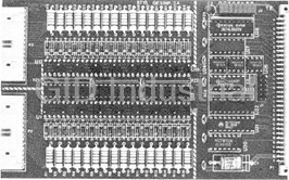
GESPAC GESBUS Interconnection Backplane for G-64 and G-96 Euroboards.
Part Number
GESBUS
Price
Request Quote
Manufacturer
GESPAC
Lead Time
Request Quote
Category
PRODUCTS - G
Datasheet
GESPAC-GESBUS-Interconnection-Backplane-for-G-64-and-G-96-Euroboards-datasheet1-189646165.pdf
629 KiB

Extracted Text
PRELIMIN Among the numerous buses existing for microprocessor based systems, the G-64 standard offering a simple and powerful solution, has proven to the best solution available for industrial applications with all 8 or 16 bit processors. Since its introduction in 1979, the G-64 concept has become a “de facto” standard in most industrial applications. The DIN 42612 type connector (2.54mm pitch) allows the use of printed circuit boards without gold connectors or other special treatment and provides an excellent electrical connection. Furthermore the shape of the connector is also compatible with flat cable connectors. The G-64 bus uses only the rows A and B of the connector (i.e. 64 pins) which are sufficient for all 8 or 16 bit microprocessor environments. There are several versions of the GESBUS depending upon size: · GESBUS-4D with 4 slots for smaller applications · GESBUS-8D with 8 slots mounts in a 19” rack enabling the use of 8 Euroboards and one 8” disk drive · GESBUS-12D with 12 slots enables the mounting of 12 Euroboards and one or two 5 ¼” floppy disk drive in various standard “EURONORM” racks (3U) · GESBUS-16D with 16 slots · GESBUS-20D with 20 slots In November 1984, to keep ahead in the fast technological progress, Gespac introduced the G-96 Bus, which uses rows A, B and C of the DIN 42612 connector (96 pins). This expansion of the standard G-64 Bus was designed to support the following criterion: · Full compatibility with the G-64 Bus. · Multiprocessor with decentralized arbitration. · To meet 16/32 bit microprocessor requirements. · Fully terminated multilayer motherboard for high- speed transfer. · Larger addressing capability (32 Mbytes). · Possibility to mix G-96 and G-64 modules on the same motherboard. There are several versions of the G96 Bus: · GESBUS-4M with 4 slots. · GESBUS-4A with 4 slots. · GESBUS-6M with 6 slots. · GESBUS-6A with 6 slots. · GESBUS-8M with 8 slots. · GESBUS-8A with 8 slots. · GESBUS-12M with 12 slots. · GESBUS-12A with 12 slots. · GESBUS-16M with 16 slots. · GESBUS-16A with 16 slots. · GESBUS-20M with 20 slots. · GESBUS-20A with 20 slots. The differences between the G-64 and G-96 Buses mainly affect only processor and memory modules. Generally, the G- 64 interface and controller modules can be used either with G-96 and G-64. © GESPAC S.A., 1997BUS XDD-GES INTERCONNECTION BACKPLANES FOR G-64 AND G-96 EUROBOARDS Revision 0.2 MISCELLANEOUS ARY GESBUS 1..............................................................3 Date (m/d/y)Modification 1.1...........................30.101/24/97Initial edition 1.2..............................................30.209/15/98Added figures 2.1a/b, 2.2a/b, 4.1 2................................4 2.1.................................4 2.2.................................4 2.3GESBUS-4D/8D/12D/16D/20D................................5 2.4........................6 2.5GESBUS-4A/6A/8A/12A/16A/20A DIMENSIONS.7 3..................................8 3.1........................................................8 Updated revision of this document can be obtained on the 3.2WER SUPPLY......................................................8 Gespac Web sites: 3.3..............................................................8 http://www.gespac.com (USA site) http://www.gespac.ch (European site) 3.3.1................................................8 3.3.2....8 3.3.3............8 3.3.4....................8 Gespac reserves the right to change products or 3.4...............................................9 specifications detailed in this documentation at any time without notice, and assumes no responsibility for any 3.4.1..............................9 errors within this document. Gespac does not make any 3.4.2.................................9 commitment to update this information. Gespac assumes no responsibility for the use of any products described in 3.4.3..... this documentation, nor does the Company assume 3.5........................ responsibility for the functioning of undescribed features or parameters. 3.6.................. 3.7......®® CompactPCI and CompactPCI are registered 4........................................... trademarks of the PCI Industrial Computers Manufacturers 4.1GESBUS-4D/8D/12D/16D/20D.............................. 4.2...................... All other brand or product names may be trademarks or registered trademarks of their respective holders. 4.3GESBUS-4A/6A/8A/12A/16A/20A......................... 4.4...................................... 5..... 2 Page 15G-64 AND G-96 BUS SIGNAL IDENTIFICATION 14MODULE INSTALLATION 13 12GESBUS-4M/6M/8M/12M/16M/20M 11 Group (PICMG). 11PREPARATION FOR USE 10SIGNAL ELECTRICAL CHARACTERISTICS 10G-64 AND G-96 BUS CONNECTORS 10PROTECTIVE EARTH TERMINAL 10JUMPERS SELECTION ON GESBUS-A ACTIVE TERMINATIONS PASSIVE TERMINATIONS BUS TERMINATIONS BACKPLANE SPECIFICATIONS IMPORTANT NOTICE BACKPLANE WITH TERMINATIONS BACKPLANE WITHOUT TERMINATIONS INTRODUCTION BACKPLANE PO INTRODUCTION ELECTRICAL SPECIFICATIONS GESBUS-4M/6M/8M/12M/16M/20M G-96 CONNECTOR (TYPE M) G-64 CONNECTOR (TYPE D) MECHANICAL SPECIFICATIONS FM BUS IDENTIFICATION FM BUS DEFINITION (BACKPLANE) ByRev INTRODUCTION REVISION HISTORYTABLE OF CONTENTS GESBUS 1. 1.1 backplane is a printed circuit with connectors (press-fit technology) wired together by a set of buses lines. The backplane also includes Plat FASTON terminals for the power supply prepositioned holes for fixing guides and prepositioned holes for mechanical mounting in different rack types. Optionally, backplanes can be supplied with jumper positions used to short-circuit the daisy chain on unoccupied slots between 2 modules (available on G-96 Backplanes only). Different backplane lengths are use for 4 to 20 connectors numbered 1, 2, 3, …….20 from right to left when looking at the backplane from the board side. 1.2 The different bus types are described in the table 1.1. 4A6A8A 20A 64-pin connector on Row A n and B G-64 96-pin connector on Row A, n n n n n n n n n n n n B and C G-96 4 slots n n n 6 slots n n 8 slots n n n 12 slots n n n 16 slots n n n 20 slots n n n Double side PCB n n n n n Multilayer terminated PCB n n n n n n n n n n n n Power connection with n n n n n n n n n n n n n n n n n Jumpers for daisy chain n n n n n n n n n n n n Passive terminations n n n n n n n n n n n n Active terminations n n n n n n Protective earth terminal n n n n n n Note: For new design you should use only the GESBUS-A family and no longer the other family. Table 1.1 Bus identification. 3 Page FASTON DIN 42612 FORM C DIN 42612 FORM C 16A12A20M16M12M8M6M 4M20D16D12D8D4D GESBUSFEATURES BUS IDENTIFICATION The BUS DEFINITION (BACKPLANE) INTRODUCTION GESBUS 2. 2.2 backplane of the G-96 Bus uses a standard DIN 2.1 41612-C female type connector. G-96 modules use the corresponding male connector. backplane of the G-64 Bus uses a standard DIN 41612-B female type connector with the row C not Physical dimensions for implementation are shown in equipped. G-64 module uses the corresponding male figures 2.2a and 2.2b. connector. This connector ensures compatibility between G-64 and G-96. Physical dimensions for implementation are shown in90 2,8 figures 2.1a and 2.1b. 3, 05, 01 858,5 6,95 150,6,10 595,,0,6,0-622,91,12 4 +0,1900,6 +0,12,81c 1b 1a 2,0-51Figure 2.2a Backplane connector for G-96 standard.,6 ,5 0 1 2,54 31 x 2,54 = 78,74 -0,495 31 x 2,54 = 78,74 52,54,48520Note: Row C is not equipped.,, 25 17,Figure 2.1a Backplane connector for G-64 standard.18 1 85,2 94- 0,43 6 84 053,85-0,3,,9488,9452 51c 1b 1a,57,2,2843,, 462,80-1 1,71, 10 0,66,2,54460 5487,531 x 2,54 = 78,74,52,9- 0,32,2,5+0,1 2 Figure 2.2b Module connector for G-96 standard. 8,7133 144,56, 2 0,5 85,2 888,7 +0,188,9 Note: Row C is not equipped. Figure 2.1b Module connector for G-64 standard. 4 Page The G-64 CONNECTOR (TYPE D) The G-96 CONNECTOR (TYPE M)MECHANICAL SPECIFICATIONS GESBUS 2.3 Mechanical characteristics of the GESBUS-4D/8D/12D/16D/20D are illustrated in figure 2.3. Figure 2.3 GESBUS-4D to 20D mechanical characteristics. 5 Page GESBUS-4D/8D/12D/16D/20D GESBUS 2.4 GESBUS-4M/6M/8M/12M/16M/20M Mechanical characteristics of GESBUS-4M/6M/8M/12M/16M/20M are illustrated in figure 2.4. Figure 2.4 GESBUS-4M to 20M mechanical characteristics. 6 Page GESBUS 2.5 Mechanical characteristics of GESBUS-4A/6A/8A/12A/16A/20A are illustrated in figure 2.5. 1520,3220,3220,3220,3220,3220,3220,3216 6 0 3,50 2,9 0 2,7 4D7R, 8A 7 D N= AS TL SA VC RA EPTS NEI G 41, 0 50 ,+-REF202 290AXIS1N3O1 S R E T N E C S NI P 2 3 20,3220,3220,3220,3220,3220,3220,32 Figure 2.5 GESBUS-4A to 20A mechanical characteristics. 7 Page GESBUS-4A/6A/8A/12A/16A/20A DIMENSIONS GESBUS 3. 3.3 3.1 3.3.1 This section defines the electrical characteristics of theThree types of backplane are considered here, one which signals and the board materials for the G-64 and G-96is a 2-layer non-terminated, one which is a 4-layer Buses. The following items are discussed below the powerterminated by resistor networks and one which is a 5-layer supply, the backplane, the bus termination and thealso terminated by resistor networks. connectors. 3.3.2 3.2 Applications, which operate at a transfer rate up to 1 MHz, The G-64 and G-96 Buses must be supplied by threecan use a 2-side printed circuit backplane. The backplane voltages, +5Vdc, +12Vdc and -12Vdc. The +5Vdc standbyis not terminated and can support also low power (CMOS) is used for battery backup applications like CMOS RAM,applications. calendar and time-of-day devices. Ripplemaximum Minimum 3.3.3 Supply Tolerance noise atcurrent per slottemperat. voltage full(board)** (A)Range For systems operating at a transfer rate faster than 1 MHz, (Vdc)(%)loadG-64G-96(convert. a multilayer printed circuit is used for the backplane. (mVpp)BusBusCooling) Generally, the asynchronous systems operate at transfer +5+5/-3503(2pins)4,5(3pins)0/55 °Crates faster than 1 MHz and will require a terminated backplane. +12+5/-3501(1pin)1(1pin)0/55 °C -12+5/-3501(1pin)1(1pin)0/55 °C The modules operating on this type of backplane are +5batt+0/-40501(1pin)1(1pin)0/55 °C equipped with 48 mA driver devices, which will drive up to Reference-5(4pins)8(8pins)- 20 modules and the TERMINATION on the bus. Note: * The tolerance must be respected throughout the backplane length. 3.3.4 ** The total maximum current for a backplane should not exceed the limits specified in table The specifications for the backplanes with and without (see 3.3.4). terminations are shown in 3.2. There are several Table 3.1 Power supply specification. techniques to build multilayer backplanes. However, the signal characteristic impedance should not be much lowerDIELECTRIC than 100 Ohms, thus the GESBUS-M and the GESBUS-A use a structure as illustrated in figures 3.1 and 3.2. MICROSTRIP LINEDIELECTRIC 1h MICROSTRIP LINE 12hh 1h m m 51723hh5h.m2m1 h813.h3 21hh21hh VOLTAGE PLANES 11STRIPLINEhhVOLTAGE PLANESww 87 5.98h2 Zo = ln( ) h1 = 0.035 mm875.98h2 0.8w + h1 Er+1.41 Zo = lnh2 = 0.5 mm( ) 0.8w +h1h1 = 0.07 mmZo = characteristicline - impedance.h3 = 1.435 mmrE+1.41h2 = 1.25 mmw = 0.25 mm Er = relativedielectriccons tan te(Er = 5)h3 = 0.4 mm Zo =characteristicline -impedance . w = 3.18 mm rE=relativedielectricconstanteEr( =5) Figure 3.2 GESBUS-A multilayer backplane structure. Figure multilayer backplane structure. 8 Page 3.1 GESBUS-M BACKPLANE SPECIFICATIONS GND .*% max BACKPLANE WITH TERMINATIONS POWER SUPPLY BACKPLANE WITHOUT TERMINATIONS INTRODUCTIONINTRODUCTION BACKPLANEELECTRICAL SPECIFICATIONS GESBUS 2 sides+5Vdc Multilayer Backplanewithout terminated terminations Resistance from source 20m W10m W to any connector: +5V 330 Ohms Resistance from source 100m W50m W to any connector: ±12V Resistance from sourceBus line 1W1W to any connector: other signals Current total: +5V20A max.35A max. Current total: ±12V 470 Ohms Capacitive load per card 20pF max.20pF max. slot Spur length 50mm max.50mm max. (bus to driver or receiver) Note: The termination should be located directly on the backplane at each bus line extremity. It is Card connector number20 max.20 max. important to decouple correctly the power Total bus length500mm max.500mm max. supply very close to the termination networks. Note: * For a current higher than 6A, it is Figure 3.3 Passive bus termination. recommended to apply the power at both ends of a 2 sided backplane. 3.4.2 Table 3.2 Backplane electrical characteristics. Thevenin generator is used to terminate the bus signals at both end of the backplane. Typical consumption of an 3.4 unpopulated backplane with active terminations is 60mA (@+5Vdc). Thevenin network termination is used on each end of the multilayer buses for all signals except the daisy chain. TheThe active termination is illustrated in the following figure. resistor network values are chosen in order that the drivers can drive up to 20 modules and the bus terminations.194 Ohms Bus line 3.4.1 + A 330/470 Ohms network is use to terminate the bus 2.94Vdcsignals at both ends of the multilayer backplane. The buffer devices must be of type 48mA to drive up to 20 - modules and the terminations on the bus. An alternative is proposed to terminate the 2 side’s buses with a network module (GESTER-1) which allows 48mA as well as 24mA buffer device to drive the modules and termination. The Figure 3.4 Active terminations. network, which is proposed, is of 608/1000 Ohms at one end of the bus. Typical consumption of an unpopulated backplane with passive terminations is 1.125A (@+5Vdc). The passive termination used is illustrated in the figure 3.3. 9 Page PASSIVE TERMINATIONS A BUS TERMINATIONS A ACTIVE TERMINATIONS 4A max.4A max. max. max. max. max. max. max. GESBUS 3.4.3 3.6 On the GESBUS-A family, users have the choice betweenThe G-64 and G-96 Buses use DIN 42612 connectors passive terminations or active terminations. A 3-pin jumperwhich are characterized by the IEC DIN 42610 makes this selection for each slot. This selection is shownspecification. The parameters in table 3.4 are extracted on figures 3.5 and 3.6.from IEC 603-2 specification class 2. 3333 Current per contact2A (20 ° 2222 Resistance per contact0.02 Ohm 1111 Insertion time400 J8 J9 J10 J11 Test voltage100Veff/50Hz Figure 3.5 Passive termination. Temperature range-55 to +125 °C Isolation resistance10MOhms 3333 Table 3.4 Electrical specifications for backplane and2222 board connectors.1111 J8 J9 J10 J11 3.7 Figure 3.6 Active termination. Note: This jumpers numeration is valid for the GESBUS-8A only. The following table gives youThe signal requirements on G-64 and G-96 Buses are the equivalence for the other GESBUS-A familyillustrated on figure 3.7. buses. Signal States are: Low level, High level. 8A4A6A12A16A20A Transition lows too high level (rising edge). J8J4J6J12J16J20 Transition high to low level (falling edge). J9J5J7J13J17J21 J10J6J8J14J18J22 J11J7J9J15J19J23 +5V ……………………………… Termination voltage 2.9-3V…… Table 3.3 Jumpers correspondence. VOH min. 2.4V…………………. Noise margin VIH min. 2V 3.5 …………………….. Transition or Undefined area A new terminal is available on the GESBUS-A type, the VIL max. 0.8V ………………….. “Protective Earth”. The Protective Earth must be Noise margin connected to the chassis. Capacitors are located on the VOL max. 0.6V …………………backplane between each supply terminals and the GND 0V Protective Earth to respect EMC. …………………………. Protective Earth conductor insulation shall be green with a Figure 3.7 Signal levels. yellow stripe. 10Page PROTECTIVE EARTH TERMINAL VCC GESBUSGESBUSGESBUSGESBUSGESBUSGESBUS SIGNAL ELECTRICAL CHARACTERISTICS C) G-64 AND G-96 BUS CONNECTORSJUMPERS SELECTION ON GESBUS-A GESBUS 4. 4.1 The GESBUS-4D to 20D are ready for use. The regulator for -5V does not exist anymore on these backplanes and the user should provide this voltage if it is required (only for old boards with 2708 EPROM or 4116 DRAM devices). The power supply voltages are identified on the PCB serigraphy. Connections are made by flat Faston terminals located on the PCB soldier side at the bottom. A resistor R (1K to 4K7) can be mounted to provide a high level on Chain out of connector 1. This is normally not required since this signal is usually provided directly on GESPAC boards. The figure 4.1 shows the GESBUS-4D implementation as an example. 4132 D N G AAAA 111 1222 2333 3444 4555 5666 6777 7888 8999 9101010 10111111 11121212 12131313 13141414 14151515 15161616 16171717 17181818 18191919 19202020 20212121 21222222 22232323 23242424 24252525 25262626 26 111J3J2J127 T A 292929BV 3030305V - 5313131 +32323232 VDVDV 252NN 11+GG-+ GESBUS-4D8809 Figure 4.1 GESBUS-4D implementation 11Page GESBUS-4D/8D/12D/16D/20D PREPARATION FOR USE GESBUS 4.2 GESBUS-4M/6M/8M/12M/16M/20M multilayer terminated GESBUS-4M to 20M are ready for use. The jumpers on J1, J2… Jn allows, when installed, to propagate the daisy chain from one connector to the next on the left side (chain out to chain in). The power supply voltages are identified on the PCB serigraphy. Connections are made by either a flat Faston or screw terminals located on the PCB soldier side at the bottom. It is recommended to provide more than a single connection for the GND and the +5V and to place these power connections at the bus extremities when using 2 wires per voltage. The figure 4.2 shows the GESBUS-6M implementation as an example. GNDGNDGND+5V+5V 416532 CACACACACACA 111111 11111 J5J4J3J2J1 323232323232 GND+12V PWFC30C29+5V BAT-12V GESBUS-6M 9209 Note: For the other backplanes, refer to the PCB serigraphy to identify the power supply locations. Figure 4.2 GESBUS-6M implementation 12Page The GESBUS 4.3 multilayer terminated GESBUS-4A to 20A are ready for use. The jumpers J1, J2… Jn allows, when installed, to propagate the daisy chain from one connector to the next on the left side (chain out to chain in). The power supply voltages are identified on the PCB serigraphy. Either a flat Faston or screw terminals located makes connections on the PCB soldier at the bottom. It is recommended to provide more than a single connection for the GND and the +5V and to place these connections at the bus extremities when using 2 wires per voltage. The figure 4.3 shows the GESBUS-8A implementation as an example. GESBUS-8A 10 1198GNDJJJJ9550 1111 87654321 C AC AC AC AC AC AC AC A 1 1 1 1 1 1 1 1 1111111 J7J5J4J3J2J1J6 32 32 32 32 32 32 32 32 PE+12VPWF+5VC30GNDC29+5V BAT-12VPE Note: For the other backplanes, refer to the PCB serigraphy to identify the power supply locations. Figures 4.3 GESBUS-8A implementation. 13Page power The GESBUS-4A/6A/8A/12A/16A/20A GESBUS 4.4 There is no specific position to install G-64 or G-96 modules on the backplane except when using the daisy chain, which is required to set up priority between several vectored interrupt sources or DMA modules. All modules using this feature are plugged into adjacent connectors to form a group with a continuous daisy chain. At least the first module in the chain is supplied with a pull-up resistor to start the chain. The module arrangement is shown in figure 4.4. DMAInterrupt Other modulemodule CPUmodules groupgroup Chain propagation Note: - The CPU has a pull-up resistor on the chain out signal that can be used to start the chain in a group. - The 2 group locations can be exchanged. - A module which does not use the chain can be plugged in a group if its chain in and chain out pins are short circuited. - An empty connector in a group must have the chain in and chain out signals short-circuited. The GESBUS- 4M to 20M and GESBUS-4A to 20A are provided with jumpers allowing to propagate the chain between any pair of bus connectors. Figure 4.4 Module arrangement for daisy chain use 14Page MODULE INSTALLATION GESBUS Note: Overlined terms are active or true when the 5. voltage is low, other terms when voltage is high. Table 5.1 G-64/G-96 Bus signal identification The signal names are identified in the table 5.1. For their Six G-64 functions have changed in the G-96 concept. definition and characteristics refer to the G-64/G-96 Speci- fications manual. These functions are shown in the table 5.2. Pinold G-64G-96 W CW BW ADefinition 16b 1 17b A16A8A02 18b A17A9A13 10a A18A10A24Address 18aHalt Ack A19A11A35line 29a-5VPWF A20A12A46A0 to (Power Fail) A21A13A57A23 A22A14A68 Table 5.2 New functions A23A15A79 10 BWD 11 LWORD DS1 DS0 12Control 13lines Enable 14and Reserved 15interrupt Reserved 16lines 17 R / W 18 IACk 19 D12 D8 20 P5 D13 D9 21Data lines P4 D14 D10 22D0 to P3 D15 D11 23D16 and P2 D4 D0 24Arbitration P1 D5 D1 25lines P0 D6 D2 26 D7 D3 27 Page ReservedChain InChain Out28Miscellan. Reserved +5Vbat.PWF 29 Reserved-12 V+12 V30 +5 V+5 V+5 V31 32 15Page GND/AGNDGNDGND Power BERRSYSFAIL LOCK GND IRQ4VED IRQ2IRQ5 VMAIRQ1IRQ3 DTACKNMI VPARES SYCLKGND HALTBBUSYBARB BGRTBRQ IRQ4 BGRTBGRT IACKIACK IRQ2FIRQ PowerGNDGNDGND IRQ1IRQ RORORO IDENTIFICATION G-64 AND G-96 BUS SIGNAL GESBUS 50 W. Hoover Ave. Tel. Tel.Tel.Tel.Tel. Printed in Switzerland16Page +33 (1) 69 85 36 60Fax+81 (3) 3478 8648Fax+1 (602) 962 5750Fax+41 (22) 794 64 77Fax 6181 24051+49 (0) Fax+33 (1) 69 85 33 73+81 (3) 3470 0640+1 (602) 962 555906 21 00+41 (22) 7 +49 (0) 6181 2405291194 Saint Aubin CedexTokyo 107-0062 Japan1-800-4-GESPACSwitzerland 63450 HanauBât. EpicureMinato-kuMesa, AZ 852101228 Geneva Langstrasse 76Les AlgorithmesMinami Aoyama 1-15-1818, chemin des Aulx Gespac GmbHGespac Systemes S.A.Gespac Co, Ltd.Gespac Inc.Gespac S.A. GERMANYFRANCEFAR EASTUSAINTERNATIONAL Notes GESBUS
Frequently asked questions
What makes Elite.Parts unique?

What kind of warranty will the GESBUS have?
Which carriers does Elite.Parts work with?
Will Elite.Parts sell to me even though I live outside the USA?
I have a preferred payment method. Will Elite.Parts accept it?


What they say about us
FANTASTIC RESOURCE
One of our top priorities is maintaining our business with precision, and we are constantly looking for affiliates that can help us achieve our goal. With the aid of GID Industrial, our obsolete product management has never been more efficient. They have been a great resource to our company, and have quickly become a go-to supplier on our list!
Bucher Emhart Glass
EXCELLENT SERVICE
With our strict fundamentals and high expectations, we were surprised when we came across GID Industrial and their competitive pricing. When we approached them with our issue, they were incredibly confident in being able to provide us with a seamless solution at the best price for us. GID Industrial quickly understood our needs and provided us with excellent service, as well as fully tested product to ensure what we received would be the right fit for our company.
Fuji
HARD TO FIND A BETTER PROVIDER
Our company provides services to aid in the manufacture of technological products, such as semiconductors and flat panel displays, and often searching for distributors of obsolete product we require can waste time and money. Finding GID Industrial proved to be a great asset to our company, with cost effective solutions and superior knowledge on all of their materials, it’d be hard to find a better provider of obsolete or hard to find products.
Applied Materials
CONSISTENTLY DELIVERS QUALITY SOLUTIONS
Over the years, the equipment used in our company becomes discontinued, but they’re still of great use to us and our customers. Once these products are no longer available through the manufacturer, finding a reliable, quick supplier is a necessity, and luckily for us, GID Industrial has provided the most trustworthy, quality solutions to our obsolete component needs.
Nidec Vamco
TERRIFIC RESOURCE
This company has been a terrific help to us (I work for Trican Well Service) in sourcing the Micron Ram Memory we needed for our Siemens computers. Great service! And great pricing! I know when the product is shipping and when it will arrive, all the way through the ordering process.
Trican Well Service
GO TO SOURCE
When I can't find an obsolete part, I first call GID and they'll come up with my parts every time. Great customer service and follow up as well. Scott emails me from time to time to touch base and see if we're having trouble finding something.....which is often with our 25 yr old equipment.
ConAgra Foods