

 Manufacturers
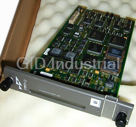
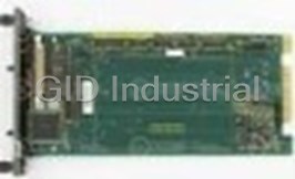
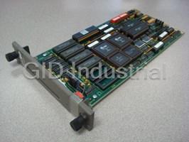
BAILEY CONTROLS NTRL 02

Description
NTRL 02
Part Number
NTRL 02
Price
Request Quote
Manufacturer
BAILEY CONTROLS
Lead Time
Request Quote
Category
COMPONENTS
Datasheet

Extracted Text
SECTION 1 - INTRODUCTION OVERVIEW The NTRL02 Fiber Optic Remote Link Termination Unit and NTRL03 Electrical Remote Link Termination Unit provide con- nections for IMRIO02 slave modules, communication cables, control stations (no analog output bypass capability), and digi- tal indicator stations. NTRL02 and NTRL03 termination units (TRL) can be connected to the NTCS04 termination unit. This enables the IMRIO02 slave module to communicate over the station link to stations for analog output bypass capability and allows the connection of additional stations. Figure 1-1 shows an example NTRL02 and NTRL03 termination unit application. INTENDED USER System engineers and technicians should read this manual before installing and placing the NTRL02 or NTRL03 termina- tion unit into operation. Personnel installing this module should have a basic knowledge of fiber optic cables and connections. COMMUNICATION HIGHWAY (INFI-NET OR PLANT LOOP) COMMUNICATION COMMUNICATION MODULES MODULES CONTROLWAY OR MODULE BUS CONTROLWAY OR MODULE BUS IMMFP03 IMMFP03 SLAVE EXPANDER BUS SLAVE EXPANDER BUS SLAVE EXPANDER BUS SLAVE EXPANDER BUS IMRIO02 IMRIO02 IMRIO02 IMRIO02 IMCIS02 IMCIS02 (RMP) (RSP) (RSP) (RMP) OTHER SLAVE OTHER SLAVE OTHER SLAVE OTHER SLAVE MODULES MODULES MODULES MODULES NTRL02 NTRL02 NTCS04 NTCS04 NTRL03 NTRL03 FIBER OPTIC LINK ELECTRICAL LINK ANALOG AND ANALOG AND DIGITAL I/O DIGITAL I/O IISAC01 IISAC01 IISAC01 IISAC01 STATION STATION STATION STATION T00750A Figure 1-1. Possible NTRL02 and NTRL03 Termination Unit Applications OVERVIEW I-E96-429A 1 - 1 ® INTRODUCTION HARDWARE DESCRIPTION The NTRL02 termination unit is a single printed circuit board that attaches to a NFTP01 Field Termination Panel located inside the INFI 90 cabinet. The NTRL02 termination unit has three socket connectors (P1, P2, and P3), two fiber optic cable connectors (TX and RX), and two terminal blocks (TB1 and TB2). • Connector P1 allows the passage of signals from the termi- nation unit to an IMRIO02 Remote I/O Slave Module. • Connector P2 provides a station link (with analog bypass capability) to an NTCS04 termination unit. • Connector P3 provides a station link to single or multiple control stations (no analog bypass capability) and/or indi- cator stations. • The TX and RX connectors enable communication over fiber optic cable between local (master) and remote (slave) NTRL02 termination units. This communication link, using Bailey Controls recommended fiber optic cable, can have a maximum length of three kilometers (10,000 feet). The TX connector couples the output optical signals from the ter- mination unit to the fiber optic cable. The RX connector couples the input optical signals from the fiber optic cable to the termination unit. Refer to the FIBER OPTIC POWER BUDGET CALCULATION in Section 2 for more information about maximum fiber optic cable lengths and allowable number of connections. • Terminal block TB1 connects a station link between redun- dant NTRL02 termination units together. Terminal block TB2 is not used. The NTRL03 termination unit is a single printed circuit board that attaches to a NFTP01 Field Termination Panel located inside the INFI 90 cabinet. The NTRL03 termination unit has three socket connectors (P1, P2, and P3), two coaxial cable connectors (J1 and J2), and two terminal blocks (TB1 and TB2). • Connector P1 connects a cable from an IMRIO02 Remote I/ O Slave Module that passes signals to the termination unit. • Connector P2 provides a station link (with analog bypass capability) to a NTCS04 termination unit. • Connector P3 provides a station link to single or multiple control stations (no analog bypass capability) and/or indi- cator stations. HARDWARE DESCRIPTION 1 - 2 I-E96-429A INTRODUCTION • The J1 (IN) and J2 (OUT) connectors enable communica- tion between a local (master) NTRL03 termination unit and one or more (a maximum of 16) remote (slave) NTRL03 ter- mination units. The total communication link can have a maximum length of three kilometers (10,000 feet). The J1 connector couples input data from the cable to the termi- nation unit. The J2 connector couples output data from the termination unit to the cable. • Terminal block TB1 allows the wiring of the output commu- nication signals (same output as connector J2). • Terminal block TB2 allows the wiring of the input commu- nication signals (same input as connector J1). TB2 is also used to connect station links between redundant NTRL03 termination units. INSTRUCTION CONTENT This manual contains five sections and four appendices: Introduction Contains an overview of the features, specifications and a description of the TRL termination units. Installation Describes precautions to observe when handling units and setup procedures required before unit operation. This section discusses jumper settings and installation procedures. Maintenance Provides a maintenance schedule. Repair/Replacement Details how to replace a TRL termination unit. Procedures Support Services Describes the support services (spare parts, training, docu- mentation, etc.) available from Bailey Controls Company. Appendices Provides quick reference information necessary for configuring A through D stations and associated modules. HOW TO USE THIS MANUAL Read this manual through in sequence. Read the installation section thoroughly. Do the steps in order. Complete all steps in the installation section before using a TRL termination unit. Refer to the table of contents or index to find specific informa- tion after the termination unit is operating. GLOSSARY OF TERMS AND ABBREVIATIONS Table 1-1 lists definitions of the terms and abbreviations used in this instruction. INSTRUCTION CONTENT I-E96-429A 1 - 3 ® INTRODUCTION Table 1-1. Glossary of Terms and Abbreviations Term Definition Analog Continuously variable as opposed to discretely variable. Bus A channel or path for transferring data, electrical signals and power. CIS Control I/O slave module. DCS Digital control station. A panel mounted operator device that provides monitoring and allows manipulation of a single process control loop. DIS Digital indicator station. A panel mounted device that monitors and displays digital values. Fiber Optic A data transmission cable made up of one or more tiny fibers of glass or plastic that trans- Cable mit data, in the form of light pulses, at the speed of light. FTP Field termination panel. A panel inside the INFI 90 cabinet on which to mount termination units. MFC Multi-function controller module. A multiple loop controller with data acquisition and infor- mation processing capabilities. MFP Multi-function processor module. A multiple loop controller with data acquisition and infor- mation processing capabilities. MMU Module mounting unit. A card cage that provides electrical and communication support for ® INFI 90/Network 90 modules. QRS Quick response slave module. RMP Remote master processor. RSP Remote slave processor. SAC Analog control station. Termination Unit Provides input/output connection between plant equipment and INFI 90/ Network 90 modules. NOMENCLATURE Table 1-2 is a list of related hardware. Table 1-2. Nomenclature Nomenclature Description IISAC01 Analog control station IMCIS02 Control I/O slave module IMQRS02 Quick response slave module IMRIO02 Remote I/O slave module NDCS03 Digital control station NDIS01 Digital indicator station NFTP01 Field termination panel ® NKCL01 INFI-NET coaxial cable (PVC) ® Network 90 is a registered trademark of Elsag Bailey Process Automation. ® INFI-NET is a registered trademark of Elsag Bailey Process Automation. NOMENCLATURE 1 - 4 I-E96-429A INTRODUCTION Table 1-2. Nomenclature (continued) Nomenclature Description NKCL11 INFI-NET coaxial cable (non-PVC) NKCS01 Station cable (PVC) NKCS02 Station cable with series connector (PVC) NKCS11 Station cable (non-PVC) NKCS12 Station cable with series connector (non-PVC) NKDS01 Station cable (PVC) NKDS02 Station cable with series connector (PVC) NKDS03 Station cable with series connector (PVC) NKDS11 Station cable (non-PVC) NKDS12 Station cable with series connector (non-PVC) NKDS13 Station cable with series connector (non-PVC) NKLM01 Loop interface cable (PVC) NKLM11 Loop interface cable (non-PVC) NKPL01 Plant loop twinaxial cable (PVC) NKPL11 Plant loop twinaxial cable (non-PVC) NKSE01 Serial extension cable (PVC) NKSE11 Serial extension cable (non-PVC) NKTL01 INFI-NET coaxial termination cable NTCS04 Controller/station termination unit NTRL02 Fiber optic remote link termination unit NTRL03 Electrical remote link termination unit REFERENCE DOCUMENTS Table 1-3 lists the documents referenced in this instruction. Table 1-3. Reference Documents Number Document I-E93-902-1 NDCS03 Digital Control Station I-E96-116 NDIS01 Digital Indicator Station I-E96-117 IISAC01 Analog Control Station REFERENCE DOCUMENTS I-E96-429A 1 - 5 ® INTRODUCTION Table 1-3. Reference Documents Number Document I-E96-306 IMCIS02 Control I/O Slave Module I-E96-316 IMQRS02 Quick Response Slave Module I-E96-317 IMRIO02 Remote I/O Slave Module I-E96-442 NTCS04 Controller/Station Termination Unit SPECIFICATIONS Refer to Table 1-4 for a list of the specifications of the NTRL02 and NTRL03 termination unit. Table 1-5 lists the specifica- tions of the fiber optic cable required by the NTRL02 termina- tion unit. Table 1-4. NTRL02 and NTRL03 Termination Unit Specifications Property Characteristic/Value Power Requirements NTRL02 +24 VDC (170 mA maximum) from the 24 VDC bus NTRL03 +24 VDC (118 mA maximum) from the 24 VDC bus Inputs Communication link from another TRL termination unit Station serial communication link Fiber Optic Receiver Signal Lim- -30 dBm minimum its (NTRL02 only) -10 dBm maximum Outputs Communication link to another termination unit. (Minimum power out- put of the NTRL02 fiber optic transmitter is -15 dBm). Station serial communication link 24 VDC power to attached stations Cable Insulation Specifications PVC (UL Rating CL2) 80°C (176°F) at 300 V Non-PVC (UL Rating PLTC) 90°C (194°F) at 300 V Mounting Occupies one space in a standard INFI 90 field termination panel. Electromagnetic/Radio Values are not available at this time. Keep the cabinet doors closed. Frequency Interference Do not use communication equipment any closer than 2 m from the cabinet. Ambient Temperature 0° to 70°C (32° to 158°F) Relative Humidity 0% to 95% up to 55°C (131°F) (noncondensing) 0% to 45% up to 70°C (158°F) (noncondensing) SPECIFICATIONS 1 - 6 I-E96-429A INTRODUCTION Table 1-4. NTRL02 and NTRL03 Termination Unit Specifications (continued) Property Characteristic/Value Air Quality Noncorrosive Certification CSA certified for use as process control equipment in an ordinary (nonhazardous) location. SPECIFICATIONS SUBJECT TO CHANGE WITHOUT NOTICE. 1 Table 1-5. Fiber Optic Cable Specifications Property Characteristic/Value Fiber size 62.5/125 μm Fiber attenuation -3.3 dB/km (maximum) Index Graded Wavelength 850 nm Bandwidth 100 MHz/km ® Connector type Amphenol 905 and 906 SMArt Series Maximum supported 3 km (10,000 ft) link distance Transmission mode Multimode NOTE: 1. Follow the cable manufacturers instructions for installation, testing, and main- tenance of the fiber optic cable. SPECIFICATIONS SUBJECT TO CHANGE WITHOUT NOTICE. ® Amphenol is a registered trademark of Amphenol Corporation. SPECIFICATIONS I-E96-429A 1 - 7 ®
Frequently asked questions
What makes Elite.Parts unique?

What kind of warranty will the NTRL 02 have?
Which carriers does Elite.Parts work with?
Will Elite.Parts sell to me even though I live outside the USA?
I have a preferred payment method. Will Elite.Parts accept it?


What they say about us
FANTASTIC RESOURCE
One of our top priorities is maintaining our business with precision, and we are constantly looking for affiliates that can help us achieve our goal. With the aid of GID Industrial, our obsolete product management has never been more efficient. They have been a great resource to our company, and have quickly become a go-to supplier on our list!
Bucher Emhart Glass
EXCELLENT SERVICE
With our strict fundamentals and high expectations, we were surprised when we came across GID Industrial and their competitive pricing. When we approached them with our issue, they were incredibly confident in being able to provide us with a seamless solution at the best price for us. GID Industrial quickly understood our needs and provided us with excellent service, as well as fully tested product to ensure what we received would be the right fit for our company.
Fuji
HARD TO FIND A BETTER PROVIDER
Our company provides services to aid in the manufacture of technological products, such as semiconductors and flat panel displays, and often searching for distributors of obsolete product we require can waste time and money. Finding GID Industrial proved to be a great asset to our company, with cost effective solutions and superior knowledge on all of their materials, it’d be hard to find a better provider of obsolete or hard to find products.
Applied Materials
CONSISTENTLY DELIVERS QUALITY SOLUTIONS
Over the years, the equipment used in our company becomes discontinued, but they’re still of great use to us and our customers. Once these products are no longer available through the manufacturer, finding a reliable, quick supplier is a necessity, and luckily for us, GID Industrial has provided the most trustworthy, quality solutions to our obsolete component needs.
Nidec Vamco
TERRIFIC RESOURCE
This company has been a terrific help to us (I work for Trican Well Service) in sourcing the Micron Ram Memory we needed for our Siemens computers. Great service! And great pricing! I know when the product is shipping and when it will arrive, all the way through the ordering process.
Trican Well Service
GO TO SOURCE
When I can't find an obsolete part, I first call GID and they'll come up with my parts every time. Great customer service and follow up as well. Scott emails me from time to time to touch base and see if we're having trouble finding something.....which is often with our 25 yr old equipment.
ConAgra Foods