

 Manufacturers
BAILEY CONTROLS IMMFP 12
Description
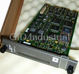
Bailey Controls IMMFP 12 Processor Module - Multi-Function INFI 90 Processor Module
Part Number
IMMFP 12
Price
Request Quote
Manufacturer
BAILEY CONTROLS
Lead Time
Request Quote
Category
COMPONENTS
Specifications
Air Quality
Noncorrosive
Ambient Temperature
0° to 70°C (32° to 158°F)
Atmospheric Pressure
Sea level to 3 km (1.86 mi)
Certification
CSA certified for use as process control equipment in an ordinary (nonhazardous) location. Factory Mutual approved for use in Class I, Division 2, hazardous locations.
Dimensions
35.56 mm wide (1.40 in.) | 177.80 mm high (7.00 in.) | 298.45 mm long (11.75 in.)
Electromagnetic/Radio Frequency Interference
Values not available at this time. Keep cabinet doors closed. Do not use communication equipment any closer than 2 meters from the cabinet.
Memory
Total: 512 kbytes ROM - 512 kbytes RAM - 256 kbytes NVRAM | Available: 347,712 bytes RAM - 194,752 bytes NVRAM
Microprocessor
32 bit processor (16 bit external bus) running at 16 MHz
Mounting
Occupies one slot in a standard INFI 90 OPEN module mounting unit.
Power Requirements
+5 VDC @ 2 A; 10 W typical
Programmability
C, BASIC, BATCH, ladder, function codes, and user-defined functions.
Redundant Communication Link Rate and Type
1 Mbaud serial link.
Relative Humidity
5% to 95% up to 55°C (131°F)(noncondensing) | 5% to 45% above 55°C (131°F)(noncondensing)
Serial Ports
Two RS-232-C ports, or one RS-485 and one RS-232-C port all of which link signals at a rate of up to 19.2 kbaud.
Station Support
Sixty-four 40-kbaud serial stations (IISAC01) or eight 5-kbaud serial stations (NDCS03 or NDIS01).
Features
- 256 kilobytes of NVRAM memory.
- 512 kilobytes of RAM memory.
- A high speed redundancy link.
- A serial communication port for station support.
- Direct memory access circuitry.
- Two general purpose serial channels.
Datasheet

Extracted Text
IMMFP12
Multi-Function Processor Module
Process Control and
Automation Solutions
from Elsag Bailey Group
WARNING notices as used in this instruction apply to hazards or unsafe practices that could result in
personal injury or death.
CAUTION notices apply to hazards or unsafe practices that could result in property damage.
NOTES highlight procedures and contain information that assists the operator in understanding the
information contained in this instruction.
WARNING
INSTRUCTION MANUALS
DO NOT INSTALL, MAINTAIN, OR OPERATE THIS EQUIPMENT WITHOUT READING, UNDERSTANDING,
AND FOLLOWING THE PROPER Elsag Bailey INSTRUCTIONS AND MANUALS; OTHERWISE, INJURY OR
DAMAGE MAY RESULT.
RADIO FREQUENCY INTERFERENCE
MOST ELECTRONIC EQUIPMENT IS INFLUENCED BY RADIO FREQUENCY INTERFERENCE (RFI). CAU-
TION SHOULD BE EXERCISED WITH REGARD TO THE USE OF PORTABLE COMMUNICATIONS EQUIP-
MENT IN THE AREA AROUND SUCH EQUIPMENT. PRUDENT PRACTICE DICTATES THAT SIGNS
SHOULD BE POSTED IN THE VICINITY OF THE EQUIPMENT CAUTIONING AGAINST THE USE OF POR-
TABLE COMMUNICATIONS EQUIPMENT.
POSSIBLE PROCESS UPSETS
MAINTENANCE MUST BE PERFORMED ONLY BY QUALIFIED PERSONNEL AND ONLY AFTER SECURING
EQUIPMENT CONTROLLED BY THIS PRODUCT. ADJUSTING OR REMOVING THIS PRODUCT WHILE IT IS
IN THE SYSTEM MAY UPSET THE PROCESS BEING CONTROLLED. SOME PROCESS UPSETS MAY
CAUSE INJURY OR DAMAGE.
NOTICE
The information contained in this document is subject to change without notice.
Elsag Bailey, its affiliates, employees, and agents, and the authors and contributors to this publication specif-
ically disclaim all liabilities and warranties, express and implied (including warranties of merchantability and
fitness for a particular purpose), for the accuracy, currency, completeness, and/or reliability of the information
contained herein and/or for the fitness for any particular use and/or for the performance of any material and/
or equipment selected in whole or part with the user of/or in reliance upon information contained herein.
Selection of materials and/or equipment is at the sole risk of the user of this publication.
This document contains proprietary information of Elsag Bailey, Elsag Bailey Process Automation, and
is issued in strict confidence. Its use, or reproduction for use, for the reverse engineering, development
or manufacture of hardware or software described herein is prohibited. No part of this document may be
photocopied or reproduced without the prior written consent of Elsag Bailey.
Preface
The IMMFP12 Multi-Function Processor Module is a powerful
stand-alone controller for use in complex control applications.
It has the processing speeds and storage capabilities necessary
for advanced control applications. The IMMFP12 module is a
user-configurable device that receives process input and out-
put through a variety of analog and digital I/O modules.
This instruction manual provides information about how the
IMMFP12 module functions and how to install, configure,
operate, and troubleshoot the module.
WBPEEUI230019A0
®
List of Effective Pages
Total number of pages in this instruction is 72, consisting of the following:
Page No. Change Date
Preface Original
List of Effective Pages Original
iii through viii Original
1-1 through 1-6 Original
2-1 through 2-4 Original
3-1 through 3-10 Original
4-1 through 4-4 Original
5-1 through 5-12 Original
6-1 through 6-4 Original
7-1 Original
8-1 Original
A-1 through A-4 Original
B-1 through B-6 Original
C-1 through C-5 Original
D-1 through D-5 Original
Index-1 through Index-2 Original
When an update is received, insert the latest changed pages and dispose of the super-
seded pages.
NOTE: On an update page, the changed text or table is indicated by a vertical bar in the outer mar-
gin of the page adjacent to the changed area. A changed figure is indicated by a vertical bar in the
outer margin next to the figure caption. The date the update was prepared will appear beside the
page number.
WBPEEUI230019A0
Table of Contents
Page
SECTION 1 - INTRODUCTION....................................................................................................1-1
OVERVIEW ..................................................................................................................1-1
INTENDED USER.........................................................................................................1-1
HARDWARE DESCRIPTION..........................................................................................1-1
Faceplate ...............................................................................................................1-2
Circuit Board .........................................................................................................1-3
HARDWARE APPLICATION...........................................................................................1-3
FEATURES...................................................................................................................1-3
INSTRUCTION CONTENT .............................................................................................1-3
HOW TO USE THIS MANUAL........................................................................................1-4
REFERENCE DOCUMENTS..........................................................................................1-4
NOMENCLATURE ........................................................................................................1-4
DOCUMENT CONVENTIONS ........................................................................................1-5
GLOSSARY OF TERMS AND ABBREVIATIONS .............................................................1-5
SPECIFICATIONS.........................................................................................................1-6
SECTION 2 - DESCRIPTION AND OPERATION........................................................................2-1
INTRODUCTION...........................................................................................................2-1
MICROPROCESSOR.....................................................................................................2-1
CLOCK AND TIMER .....................................................................................................2-2
MEMORY .....................................................................................................................2-2
I/O EXPANDER BUS ....................................................................................................2-2
I/O SECTION ...............................................................................................................2-2
SERIAL CHANNELS......................................................................................................2-3
DMA SECTION .............................................................................................................2-3
CONTROLWAY .............................................................................................................2-3
REDUNDANCY LINK ....................................................................................................2-4
STATION LINK..............................................................................................................2-4
SECTION 3 - INSTALLATION .....................................................................................................3-1
INTRODUCTION...........................................................................................................3-1
SPECIAL HANDLING ....................................................................................................3-1
UNPACKING AND INSPECTION ....................................................................................3-2
SETUP AND PHYSICAL INSTALLATION ........................................................................3-2
Dipswitch SW3 Settings .........................................................................................3-3
Dipswitch SW4 Settings .........................................................................................3-4
Special Operations .................................................................................................3-5
Jumpers J1 through J5 .........................................................................................3-6
PREPARING THE MODULE MOUNTING UNIT...............................................................3-7
Dipshunts..............................................................................................................3-7
Controlway Cable...................................................................................................3-8
INSTALLING THE TERMINATION UNIT OR MODULE ....................................................3-8
NTMP01 Termination Unit Installation ...................................................................3-8
NIMP01 or NIMP02 Termination Module Installation ..............................................3-9
INSTALLING THE MODULE..........................................................................................3-9
SECTION 4 - OPERATING PROCEDURES................................................................................4-1
INTRODUCTION...........................................................................................................4-1
STARTUP .....................................................................................................................4-1
LED INDICATORS ........................................................................................................4-1
Front Panel LEDs One through Eight .....................................................................4-2
WBPEEUI230019A0 iii
®
Table of Contents (continued)
Page
SECTION 4 - OPERATING PROCEDURES (continued)
Red/Green Status LED.......................................................................................... 4-2
STOP/RESET SWITCH................................................................................................. 4-3
MODES OF OPERATION .............................................................................................. 4-4
Configure Mode ..................................................................................................... 4-4
Execute Mode ........................................................................................................ 4-4
Error Mode ............................................................................................................ 4-4
SECTION 5 - TROUBLESHOOTING...........................................................................................5-1
INTRODUCTION .......................................................................................................... 5-1
CARD EDGE CONNECTORS ........................................................................................ 5-5
DIAGNOSTICS ............................................................................................................. 5-6
Overview ............................................................................................................... 5-6
Dipswitch Selection ............................................................................................... 5-7
LED Display .......................................................................................................... 5-9
MODULE STATUS SUMMARY .................................................................................... 5-10
SECTION 6 - MAINTENANCE.....................................................................................................6-1
INTRODUCTION .......................................................................................................... 6-1
PREVENTIVE MAINTENANCE SCHEDULE ................................................................... 6-1
EQUIPMENT AND TOOLS REQUIRED.......................................................................... 6-2
PREVENTIVE MAINTENANCE PROCEDURES .............................................................. 6-2
Printed Circuit Board Cleaning .............................................................................. 6-2
GENERAL CLEANING AND WASHING ............................................................. 6-3
EDGE CONNECTOR CLEANING ...................................................................... 6-3
Checking Connections ........................................................................................... 6-3
SECTION 7 - REPAIR/REPLACEMENT PROCEDURES ..........................................................7-1
INTRODUCTION .......................................................................................................... 7-1
MODULE REPLACEMENT PROCEDURE ...................................................................... 7-1
TERMINATION UNIT OR MODULE REPLACEMENT PROCEDURES .............................. 7-1
SECTION 8 - SUPPORT SERVICES...........................................................................................8-1
INTRODUCTION .......................................................................................................... 8-1
REPLACEMENT PARTS AND ORDERING INFORMATION.............................................. 8-1
TRAINING.................................................................................................................... 8-1
TECHNICAL DOCUMENTATION................................................................................... 8-1
APPENDIX A - IMMFP12 QUICK REFERENCE MATERIAL .................................................... A-1
INTRODUCTION ..........................................................................................................A-1
APPENDIX B - ON-LINE CONFIGURATION ............................................................................. B-1
INTRODUCTION ..........................................................................................................B-1
SETUP.........................................................................................................................B-1
OPERATION.................................................................................................................B-1
Backup Cycle ........................................................................................................B-3
Primary Cycle ........................................................................................................B-4
iv WBPEEUI230019A0
Table of Contents (continued)
Page
APPENDIX C - NTMP01 TERMINATION UNIT CONFIGURATION........................................... C-1
INTRODUCTION.......................................................................................................... C-1
APPENDIX D - NIMP01/NIMP02 TERMINATION MODULE CONFIGURATION....................... D-1
INTRODUCTION.......................................................................................................... D-1
List of Figures
No. Title Page
1-1. Example IMMFP12 Module Applications .................................................................1-2
2-1. IMMFP12 Module Functional Block Diagram ..........................................................2-1
3-1. IMMFP12 Module Layout .......................................................................................3-3
3-2. Controlway Cable Installation ................................................................................3-9
4-1. IMMFP12 Front Panel LEDs and Controls ..............................................................4-2
5-1. IMMFP12 Troubleshooting Flowchart (Serial Port) ..................................................5-4
5-2. IMMFP12 Troubleshooting Flowchart (Status LED).................................................5-5
5-3. Diagnostic Dipswitch Settings ................................................................................5-8
5-4. LEDs - Pass/Fail..................................................................................................5-10
B-1. Backup MFP Module Operating Cycle .................................................................... B-5
B-2. Primary MFP Module Operating Cycle ................................................................... B-6
C-1. DTE Jumper Configuration for NTMP01 Termination Unit ..................................... C-1
C-2. DCE Jumper Configuration for NTMP01 Termination Unit ..................................... C-2
C-3. NTMP01 Nonhandshake Jumper Configuration ..................................................... C-2
C-4. NTMP01 Loopback Jumper Configuration ............................................................. C-3
C-5. NTMP01 Jumpers J3 through J10 Configuration ................................................... C-3
C-6. NTMP01 Jumpers J14 through J17 Configuration ................................................. C-4
C-7. NTMP01 Connector Assignments and Jumper Locations ....................................... C-4
C-8. NTMP01 Cable Connections for Redundant MFP Modules ...................................... C-5
C-9. NTMP01 Cable Connections for a Single MFP Module ............................................ C-5
D-1. DTE Jumper Configuration for NIMP01 Termination Module ................................. D-2
D-2. DCE Jumper Configuration for NIMP01 Termination Module ................................. D-2
D-3. NIMP01 Nonhandshake Jumper Configuration ...................................................... D-3
D-4. NIMP01 Loopback Jumper Configuration .............................................................. D-3
D-5. NIMP01 Jumpers J5 through J10 Configuration.................................................... D-3
D-6. NIMP01 Jumpers J14 through J17 Configuration .................................................. D-4
D-7. NIMP01 Connector Assignments and Jumper Locations ........................................ D-4
D-8. NIMP01 and NIMP02 Cable Connections for Redundant MFP Modules ................... D-5
D-9. NIMP01 Cable Connections for a Single MFP Module ............................................. D-5
WBPEEUI230019A0 v
®
List of Tables
No. Title Page
1-1. Reference Documents ............................................................................................ 1-4
1-2. Nomenclature........................................................................................................ 1-5
1-3. Glossary of Terms and Abbreviations ..................................................................... 1-5
1-4. Specifications ........................................................................................................ 1-6
3-1. IMMFP12 Dipswitch SW3 Settings ......................................................................... 3-3
3-2. Example IMMFP12 Module Address Settings.......................................................... 3-4
3-3. IMMFP12 Dipswitch SW4 Normal Operation Settings ............................................. 3-4
3-4. IMMFP12 Dipswitch SW4 Special Operation Settings ............................................. 3-5
3-5. IMMFP12 Jumpers J1 through J5 Settings ............................................................ 3-7
5-1. IMMFP12 Module Error Codes ............................................................................... 5-1
5-2. Other IMMFP12 Module LED Conditions................................................................ 5-3
5-3. IMMFP12 Connector P1 Pin Assignments ............................................................... 5-5
5-4. IMMFP12 Connector P2 Pin Assignments ............................................................... 5-6
5-5. IMMFP12 Connector P3 Pin Assignments ............................................................... 5-6
5-6. IMDSM05 Switch Settings for IMMFP12 Tests ........................................................ 5-7
5-7. IMDSM05 Jumper Settings for IMMFP12 Tests ...................................................... 5-7
5-8. Diagnostic Tests .................................................................................................... 5-8
5-9. IMMFP12 Module Status Report .......................................................................... 5-11
5-10. Field Descriptions of the IMMFP12 Module Status Report .................................... 5-11
6-1. Preventive Maintenance Schedule .......................................................................... 6-2
8-1. Spare Parts List ..................................................................................................... 8-1
A-1. IMMFP12 Dipswitch SW3 Settings .........................................................................A-1
A-2. IMMFP12 Dipswitch SW4 Settings .........................................................................A-1
A-3. IMMFP12 Jumper J5 Settings................................................................................A-2
A-4. IMMFP12 Module Error Codes ...............................................................................A-2
A-5. Other IMMFP12 Module LED Conditions................................................................A-4
B-1. Legend of Symbols .................................................................................................B-2
B-2. Backup Cycle ........................................................................................................B-3
B-3. Primary Cycle ........................................................................................................B-5
vi WBPEEUI230019A0
Safety Summary
GENERAL Equipment Environment
WARNINGS All components, whether in transportation, operation or storage,
must be in a noncorrosive environment.
Electrical Shock Hazard During Maintenance
Disconnect power or take precautions to insure that contact with
energized parts is avoided when servicing.
Special Handling
This module uses electrostatic sensitive devices (ESD).
SPECIFIC Disconnect power before installing dipshunts on the module mount-
WARNINGS ing unit backplane. Failure to do so will result in contact with cabinet
areas that could cause severe or fatal shock. (p. 3-7)
Wear eye protection whenever working with cleaning solvents.
When removing solvents from printed circuit boards using com-
pressed air, injury to the eyes could result from splashing solvent as
it is blown off the printed circuit board. (p. 6-1)
SPECIFIC Never operate the MFP module with the machine fault timer circuit
CAUTIONS disabled. Unpredictable module outputs and configuration corrup-
tion may result. The unpredictable module outputs may damage
control equipment connected to the MFP module. (p. 3-9)
SPECIFIC To avoid potential module damage, evaluate your system for com-
CAUTIONS patibility prior to module installation. This module uses connections
to the module mounting unit backplane that served other functions
in early Network 90 systems. (p. 3-10)
WBPEEUI230019A0 vii
®
Trademarks and Registrations
Registrations and trademarks used in this document include:
® INFI 90 Registered trademark of Elsag Bailey Process Automation
® INFI-NET Registered trademark of Elsag Bailey Process Automation
® Network 90 Registered trademark of Elsag Bailey Process Automation
viii WBPEEUI230019A0
SECTION 1 - INTRODUCTION
OVERVIEW
The IMMFP12 Multi-Function Processor Module (MFP) is one of
®
the workhorses of the INFI 90 OPEN control module line. It is
a multiple loop analog, sequential, batch and advanced con-
troller that provides powerful solutions to process control
problems. It also handles data acquisition and information
processing requirements providing true peer-to-peer commu-
nications. The comprehensive set of function codes supported
by this module handles even the most complex control strate-
gies. The INFI 90 OPEN system uses a variety of analog and
digital I/O modules to communicate with and control the pro-
cess. The MFP module communicates with a maximum of 64
modules in any combination (refer to Figure 1-1).
The MFP module has three operating modes: execute, configure
and error. In the execute mode, the MFP module executes con-
trol algorithms while constantly checking itself for errors. When
an error is found, the front panel LEDs display an error code
corresponding to the type of error found. In the configure mode,
it is possible to edit existing or add new control algorithms. In
this mode, the MFP module does not execute control algorithms.
If the MFP module finds an error while in execute mode, it auto-
matically goes into error mode. Refer to the Section 4 of this
instruction for operating mode details.
A one megabaud CPU to CPU communication link allows the
MFP module to accommodate redundant processors. This link
enables a backup MFP module to wait in a hot standby mode
while the primary MFP module executes the control algorithms.
If the primary MFP module goes off-line for any reason, a
bumpless transfer of control to the backup MFP module occurs.
INTENDED USER
Personnel installing, operating, or maintaining the MFP mod-
ule should read this manual before performing any installa-
tion, operation, or maintenance procedures. Installation
requires an engineer or technician with experience handling
electronic circuitry. Formal training in INFI 90 OPEN systems
and configuration (especially function codes) would help when
configuring the MFP module.
HARDWARE DESCRIPTION
The multifunction processor module consists of a faceplate and
circuit board.
OVERVIEW
WBPEEUI230019A0 1 - 1
®
INTRODUCTION
®
INFI-NET OR PLANT LOO P
PRO CESS CONT RO L
NIS N P M
UNIT INTERFACE
CO NTRO LWAY
SECO NDARY PR IM ARY
MFP
MFP
I/O EXPANDER BUS
I/O I/O I/O
MODULE MODULE MO D UL E
CIS TM P
UP TO 64 M O DULE S
R S -2 32-C
OR
RS -4 85
RS -4 85
TC S
RS-485
SAC SAC SAC
T01 6 91 A
Figure 1-1. Example IMMFP12 Module Applications
Faceplate
The MFP faceplate measures 35.56 millimeters wide by 177.80
millimeters high (1.4 inches wide by seven inches high). Two
latching screws, one at the top, the other at the bottom, lock
the module assembly into the module mounting unit. A trans-
parent window on the faceplate permits viewing of LEDs one
through eight and the status LED. These LEDs display operat-
ing information. A small hole directly below the window pro-
vides access to the combination stop/reset pushbutton.
Besides locking the module in place, the faceplate also protects
the circuit components and promotes proper air flow within the
cabinet.
HARDWARE DESCRIPTION
1 - 2 WBPEEUI230019A0
INTRODUCTION
Circuit Board
The circuit board features state-of-the-art circuitry. On the
board are nonvolatile random access memory (NVRAM), random
access memory (RAM), read only memory (ROM), a microproces-
sor running at 16 megahertz, direct memory access (DMA) cir-
cuits, Elsag Bailey custom bus circuits and various support
circuitry. The board attaches to the faceplate with two screws.
The module assembly occupies one slot in a module mounting
unit.
HARDWARE APPLICATION
The multifunction processor module is ideally suited for appli-
cations requiring multiple loop control and module I/O. Since
it handles both analog and digital signals, the MFP module fits
into virtually any control scheme.
FEATURES
The MFP module has the following features:
• A high speed redundancy link.
• A serial communication port for station support.
• Two general purpose serial channels.
• Direct memory access circuitry.
• 512 kilobytes of RAM memory.
• 256 kilobytes of NVRAM memory.
INSTRUCTION CONTENT
This manual consists of eight sections and four appendices:
Introduction
This section provides an overview of the module, a description
of the hardware, a glossary of unique terms, and a table of
physical, electrical, and environmental specifications.
Description and
How the key circuits function is explained in this section.
Operation
Installation
The handling, inspection, hardware configuration, and instal-
lation aspects of the module are described in this section.
Operating Procedures
Front panel indicators and controls, and everyday operations
are discussed in this section.
Troubleshooting
This section features detailed flow charts and tables that
enable quick diagnosis of error conditions and provide correc-
tive actions.
Maintenance
Scheduled module maintenance is covered by this section.
HARDWARE APPLICATION
WBPEEUI230019A0 1 - 3
®
INTRODUCTION
Repair/Replacement This section describes how to maintain and replace the module.
Procedures
Support Services
A list of the replacement parts and an explanation of the war-
ranty policy are contained in this section.
Appendices
These appendices provide quick reference information for the
hardware configuration of the IMMFP12 module and associ-
ated termination units and modules and step by step instruc-
tions for performing on-line configuration.
HOW TO USE THIS MANUAL
Read this instruction in sequence. Read Section 3 thoroughly.
It is important to become familiar with the entire contents of
this instruction before using the MFP module. Refer to the
table of contents or index to find specific information after the
module is operating.
1. Read and perform all steps in Section 3.
2. Thoroughly read Section 4 before applying power to the
module.
3. Refer to Section 5 if a problem occurs. This section will help
to diagnose and correct a problem.
4. Refer to Section6 for scheduled maintenance require-
ments.
5. Go to Section 7 to find instructions on how to replace the
module.
6. Refer to Section 8 for replacement part and warranty infor-
mation.
REFERENCE DOCUMENTS
Table 1-1 lists the documents that provide additional informa-
tion for related equipment. Refer to them as needed.
Table 1-1. Reference Documents
Number Document
I-E96-200 Function Code Application Manual
I-E96-401 NIMP01/02 Multi-Function Processor Termination Module
I-E96-428 NTMP01 Multi-Function Processor Termination Unit
NOMENCLATURE
Table 1-2 lists the nomenclatures of the MFP module and asso-
ciated equipment used in this instruction.
HOW TO USE THIS MANUAL
1 - 4 WBPEEUI230019A0
INTRODUCTION
Table 1-2. Nomenclature
Nomenclature Hardware/Description
IMMFP12 Multi-function processor module
NIMP01/02 Multi-function processor module termination module
NKMP01 MFP redundancy cable
NKMR02 RS-232-C cable
NKSE01 Serial extension cable (PVC)
NKSE11 Serial extension cable (non-PVC)
NKTU01 Termination unit cable (PVC)
NKTU02 Termination module cable (PVC)
NKTU11 Termination unit cable (non-PVC)
NKTU12 Termination module cable (non-PVC)
NTMP01 Multi-function processor module termination unit
DOCUMENT CONVENTIONS
The ? in a nomenclature or a part number indicates a variable
for that position (e.g., IMMFP1?)
GLOSSARY OF TERMS AND ABBREVIATIONS
Table 1-3 lists the definitions of terms and abbreviations used
in this instruction that are unique to Elsag Bailey.
Table 1-3. Glossary of Terms and Abbreviations
Term Description
Configuration The act of setting up equipment to accomplish specific functions or a list of parame-
ters associated with such a setup.
Controlway High speed, redundant, peer-to-peer communication link. Used to transfer informa-
tion between intelligent modules within a process control unit.
Dipswitch A dual in-line package that contains switches.
EWS Engineering work station.
Executive Block Fixed function block that determines overall module operating characteristics.
Function Block The occurrence of a function code at a block address of a module.
Function Code An algorithm which manipulates specific functions. These functions are linked
together to form the control strategy.
I/O Expander Bus Parallel communication bus between the master and I/O modules.
MFP Multifunction processor module. A multi-loop controller with data acquisition and
information processing capabilities.
MFT Machine fault timer. Reset by the processor during normal operation. If not reset
regularly, the MFT times out and the module stops.
MMU Module mounting unit. A card cage that provides electrical and communication sup-
®
port for INFI 90 OPEN/ Network 90 modules.
Module Bus Peer-to-peer communication link used to transfer information between intelligent
modules within a process control unit.
Node A point of interconnection to a network.
DOCUMENT CONVENTIONS
WBPEEUI230019A0 1 - 5
®
INTRODUCTION
Table 1-3. Glossary of Terms and Abbreviations
(continued)
Term Description
PCU Process control unit. A node on the plantwide communication network containing
control and I/O modules.
SAC Analog control station.
Termination Module Provides input/output connection between plant equipment and the INFI 90 OPEN/
Network 90 modules.
Termination Unit Provides input/output connection between plant equipment and the INFI 90 OPEN/
Network 90 modules.
SPECIFICATIONS
Refer to Table 1-4 for the specifications of the IMMFP12
Multi-Function Processor Module.
Table 1-4. Specifications
Property Characteristic/Value
Microprocessor 32 bit processor (16 bit external bus) running at 16 MHz
Memory
Total 512 kbytes ROM
512 kbytes RAM
256 kbytes NVRAM
Available 347,712 bytes RAM
194,752 bytes NVRAM
Power Requirements +5 VDC @ 2 A; 10 W typical
Serial Ports Two RS-232-C ports, or one RS-485 and one RS-232-C port all of
which link signals at a rate of up to 19.2 kbaud.
Station Support Sixty-four 40-kbaud serial stations (IISAC01) or
eight 5-kbaud serial stations (NDCS03 or NDIS01).
Redundant Communication Link 1 Mbaud serial link.
Rate and Type
Electromagnetic/Radio Values not available at this time. Keep cabinet doors closed. Do not
Frequency Interference use communication equipment any closer than 2 meters from the cabi-
net.
Programmability C, BASIC, BATCH, ladder, function codes, and user-defined functions.
Dimensions 35.56 mm wide (1.40 in.)
177.80 mm high (7.00 in.)
298.45 mm long (11.75 in.)
Mounting Occupies one slot in a standard INFI 90 OPEN module mounting unit.
Ambient Temperature 0° to 70°C (32° to 158°F)
Relative Humidity 5% to 95% up to 55°C (131°F)(noncondensing)
5% to 45% above 55°C (131°F)(noncondensing)
Atmospheric Pressure Sea level to 3 km (1.86 mi)
Air Quality Noncorrosive
Certification CSA certified for use as process control equipment in an ordinary (non-
hazardous) location. Factory Mutual approved for use in Class I, Divi-
sion 2, hazardous locations.
SPECIFICATIONS SUBJECT TO CHANGE WITHOUT NOTICE.
SPECIFICATIONS
1 - 6 WBPEEUI230019A0
SECTION 2 - DESCRIPTION AND OPERATION
INTRODUCTION
The IMMFP12 Multi-Function Processor Module functions like
a series of functional blocks working together. To explain how
the MFP module works, this section shows MFP module func-
tionality as a block diagram (refer to Figure 2-1) and then
explains each block in the following text.
CLOCK/
TIMER
MACHINE
FAU LT MICROPROCESSOR
TIMER
RAM ROM NVRAM
DATA BUS
I/O I/O
DM A SECTIO N
SERIAL
SECTION
EXPANDER
PORTS
BUS
REDUNDANCY DCS
CONTROLWAY
LEDS,
LINK LINK
SWITCHES
AND
CONTROL A B
TO
TO
OUTPUT
P2 P3
TO TO TO
P1 P3 P3
T01698A
Figure 2-1. IMMFP12 Module Functional Block Diagram
MICROPROCESSOR
The microprocessor, operating at 16 megahertz, enables mod-
ule operation and control. The operating system instructions
and function code library of the microprocessor reside in read
only memory (ROM). Since the microprocessor is responsible
for overall module operation, it communicates with all the
functional blocks. The microprocessor also constantly triggers
the machine fault timer (MFT) circuit. If the microprocessor or
module software fails and the MFT circuit is not reset, the MFT
INTRODUCTION
WBPEEUI230019A0 2 - 1
®
DESCRIPTION AND OPERATION
circuit issues a board-wide reset and the status LED turns red.
This condition is known as a fatal error.
CLOCK AND TIMER
The clock section provides the clock signals that drive the mod-
ule at 16 megahertz. Additionally, this section supplies the
lower order clock signals for the on-board serial links, and the
system timer for uniform control algorithm execution. All clock
signals originate from either the 32 megahertz or 7.3728 mega-
hertz oscillators on the multifunction processor module.
The timer section keeps the multifunction processor module
task scheduling at the proper intervals. One of the UART
devices used for serial communication contains the timer
section.
MEMORY
The MFP module contains 512 kilobytes of ROM memory, 512
kilobytes of random access memory (RAM) and 256 kilobytes of
nonvolatile random access memory (NVRAM). It is important to
remember that only 347,712 bytes of RAM memory and
194,752 bytes of NVRAM memory are available for user config-
urations. The ROM memory holds the operating system
instructions for the microprocessor. The RAM memory provides
temporary storage and a copy of the module configuration. The
NVRAM memory holds the module configuration (control strat-
egy designed with function codes). The ability to retain infor-
mation when power is lost makes this type of memory unique.
Back-up batteries in the NVRAM device that keep the memory
active makes this possible.
A key feature of the RAM and ROM memory of the MFP module
is that it requires only one wait state. This means that the
microprocessor need only wait one clock cycle before it can
check the data in memory. This results in quicker operation.
I/O EXPANDER BUS
The I/O expander bus resides on the backplane of the module
mounting unit. This bus, an eight bit parallel bus, provides the
communication path for I/O data between control and I/O
modules. It supports up to 64 low power I/O modules. The bus
uses a protocol designed by Elsag Bailey to ensure data integ-
rity. The bus bandwidth is 500 kilobytes per second, however
actual throughput is about 100 kilobytes per second.
I/O SECTION
The input and output section interface allows the microproces-
sor to read the switches that tell it how to operate and what
CLOCK AND TIMER
2 - 2 WBPEEUI230019A0
DESCRIPTION AND OPERATION
address it has. This section contains the latches whose
outputs connect to LEDs one through eight and the status
LED. Additionally this section contains an output that desig-
nates this module as the primary module. Upon a failover, this
output turns off and the backup module output energizes as it
takes over. This output actuates an LED that indicates which
module is the primary.
Additionally, the input and output section monitors the stop/
reset pushbutton. Pressing the pushbutton once causes this
section to bring the module to an orderly stop after completing
any input or output function currently in progress. Pressing
the pushbutton a second time resets the module.
SERIAL CHANNELS
The MFP module contains two independent, general purpose
serial channels. One use is for language support (C and
BASIC). Each channel supports standard baud rates up to
19.2 kilobaud. The appropriate termination unit or termina-
tion module uses standard D-type connectors. The NTMP01,
NIMP01, or NIMP02 termination device optically isolates these
communication channels. This optical isolation eliminates the
need to tie chassis ground to system common and alleviates
the potential of damage from ground currents. One channel
can also be used as a RS-485 connection.
DMA SECTION
The microprocessor sets this section for direct memory access
or DMA. The DMA section allows data being received or trans-
mitted over the various communication paths to be transferred
directly to or from the RAM memory without microprocessor
intervention. This process is known as cycle stealing. It greatly
reduces the overhead associated with the microprocessor doing
such data moves. This circuitry is used for the higher speed
communication paths where the microprocessor would be
overloaded handling the data moves, specifically Controlway.
The 40-kilobaud station link and the redundancy link also use
this feature.
CONTROLWAY
The Controlway is the high-speed version of the module bus. It
provides a one-megabaud peer-to-peer communication link
capable of supporting up to 32 connections. The Controlway
interface is provided by a custom Elsag Bailey integrated cir-
cuit that links the MFP module to the Controlway. It has full
DMA capabilities (allowing for quicker operation), and two
redundant, independent communication channels.
SERIAL CHANNELS
WBPEEUI230019A0 2 - 3
®
DESCRIPTION AND OPERATION
There are two separate communication paths on the module
mounting unit backplane circuit allotted for Controlway com-
munications. Data is transmitted over both channels simulta-
neously and received in separate receivers where it is checked
for integrity. In this way, the Controlway minimizes the
chances that a failure on a circuit board, or the backplane will
cause loss of module communication.
As point data between intelligent modules travels on the bus,
the MFP module does a bit-by-bit comparison. The Controlway
interface also allows the MFP module to operate on the module
bus by operating in an 83.3 kilobaud mode.
REDUNDANCY LINK
The redundancy link is a one megabaud serial link between a
primary and backup MFP module in a redundant configura-
tion. This link also has full DMA capabilities. As the primary
module executes control algorithms, the backup module waits
in hot standby mode and receives a copy of all block outputs
over this link. If for any reason, the primary module fails, the
backup module takes over immediately without any process
interruption provided there is no excessive checkpoint overrun
caused by the function block configuration.
NOTE: Firmware revision levels must be the same in the primary
and secondary MFP modules. If the firmware revision level is differ-
ent and a failover occurs, the redundant MFP module may operate
erratically.
STATION LINK
The station link controls the serial communication between the
MFP module and stations. This link has two modes of opera-
tion. When used with the NDCS03 Digital Control Station, it
provides a five-kilobaud serial channel for up to eight stations.
This link connects to the NTMP01 termination unit via the
NKSE01 or NKSE11 cable. This link requires serial link wire to
connect to NIMP01 and NIMP02 termination modules.
When interfacing with the IISAC01 Analog Control Station, the
communication rate can be five kilobaud or 40 kilobaud and
the data is direct memory accessed into or out of MFP module
memory. The 40-kilobaud link supports up to 64 stations, but
requires two drivers to accomplish this. Therefore, two connec-
tors provide for two NKSE01 cables and up to 32 stations can
be driven off each. The data transmitted over both links is
identical, so the stations must have an address from zero to 63
without duplication. The five-kilobaud link supports up to
eight stations.
REDUNDANCY LINK
2 - 4 WBPEEUI230019A0
SECTION 3 - INSTALLATION
INTRODUCTION
This section explains what must be done before placing the
multifunction processor module into operation. Read, under-
stand, and complete the steps in the order they appear before
operating the MFP module.
NOTE: To avoid potential module damage, evaluate your system for
compatibility prior to module installation. This module uses connec-
tions to the module mounting unit backplane that served other func-
tions in early Network 90 systems.
Early Network 90 systems applied -30 VDC to pins 3 and 4 of the
module connector P1. This voltage is not required for INFI 90 OPEN
modules. In INFI 90 OPEN systems, pin 4 is used for the Controlway
bus.
If your system contains modules that require -30 VDC, set jumper J5
to the 30 VDC position. Doing so allows the installation of the MFP
module in a module mounting unit that uses -30 VDC and limits
communication to the module bus.
SPECIAL HANDLING
Observe these steps when handling electronic circuitry:
NOTE: Always use Elsag Bailey field static kit (part number
1948385?1 - consisting of two wrist straps, ground cord assembly,
alligator clip, and static dissipating work surface) when working with
the modules. The kit is designed to connect the technician and the
static dissipating work surface to the same ground point to prevent
damage to the modules by electrostatic discharge.
1. Use Static Shielding Bag. Keep the modules in the static
shielding bag until you are ready to install them in the system.
Save the packaging for future use.
2. Ground Bags Before Opening. Before opening a bag con-
taining an assembly with semiconductors, touch it to the
equipment housing or a ground to equalize charges.
3. Avoid Touching Circuitry. Handle assemblies by the
edges; avoid touching the circuitry.
4. Avoid Partial Connection of Semiconductors. Verify that
all devices connected to the module are properly grounded
before using them.
5. Ground Test Equipment.
INTRODUCTION
WBPEEUI230019A0 3 - 1
®
INSTALLATION
6. Use Antistatic Field Service Vacuum. Remove dust from
the module if necessary.
7. Use a Grounded Wrist Strap. Connect the wrist strap to
the appropriate grounding plug on the power entry panel. The
grounding plug on the power entry panel is connected to the
cabinet chassis ground.
8. Do Not Use Lead Pencils to Set Dipswitches. To avoid
contamination of dipswitch contacts that can result in unnec-
essary circuit board malfunction, do not use a lead pencil to
set a dipswitch.
UNPACKING AND INSPECTION
1. Examine the hardware immediately for shipping damage.
2. Notify the nearest Elsag Bailey sales office of any such
damage.
3. File a claim for any damage with the transportation com-
pany that handled the shipment.
4. Use the original packing material and container to store the
hardware.
5. Store the hardware in an environment of good air quality,
free from temperature and moisture extremes.
SETUP AND PHYSICAL INSTALLATION
This section explains how to configure and install the MFP
module. After installing the MFP module, a function block con-
figuration must be created to define the functions the module
will perform. This configuration can be created in the module
itself or can be created using a configuration tool (e.g., CAD/
TXT, EWS) and then downloaded to the module.
The MFP module has two configurable dipswitches and five
jumpers. Each dipswitch has eight poles. Refer to Figure 3-1 for
dipswitch and jumper locations. Dipswitch SW3 sets the bus
mode and module address. Dipswitch SW4 sets module options
and special operations (refer to Special Operations of this sec-
tion). Jumpers J1 through J5 are for special applications.
Dipswitch poles marked unused in tables must be kept in the
zero position. The MFP module may not operate properly if these
dipswitches are set to the one position. Since factory settings do
not reflect default settings, it is imperative that all dipswitch set-
tings be checked before putting the module into operation.
UNPACKING AND INSPECTION
3 - 2 WBPEEUI230019A0
INSTALLATION
Dipswitch SW3 Settings
Dipswitch SW3 sets the bus mode and address of the MFP
module. The MFP module can have an address from zero
-30 VD C SYSTEM
J5
(DEFAULT)
RESERVED
J5 CONTROLWAY
RESERVED
ON ON
P1
1 2 3 4 5 6 7 8 1 2 3 4 5 6 7 8
SW 3 SW 4
J5
P3
J2
J1
J3
J4
P2
M ACHINE FAULT TIM ER JU MPER S AN D PO STS
T01604A
Figure 3-1. IMMFP12 Module Layout
through 31. Address zero and one should not be used because
other MFP modules will not be able to import data from this
MFP module. All MFP modules within a process control unit
must communicate on the same communication highway
(module bus or Controlway). Table 3-1 explains the function of
each dipswitch pole. Table 3-2 shows some sample dipswitch
settings. For quick reference, record dipswitch settings in the
user setting portion of the table.
NOTE: Module addresses of redundant MFP modules must be iden-
tical. All modules within a process control unit must be set to com-
municate on either the Controlway or module bus.
Table 3-1. IMMFP12 Dipswitch SW3 Settings
User
Pole Setting Function
Setting
10 Normal run.
1 Invoke diagnostics using dipswitch
SW4.
20 Unused. Do not change setting.
SETUP AND PHYSICAL INSTALLATION
WBPEEUI230019A0 3 - 3
®
INSTALLATION
Table 3-1. IMMFP12 Dipswitch SW3 Settings
User
Pole Setting Function
Setting
1
3 0 Controlway (1 Mbaud) mode.
1 Module bus (83.3 kbaud) mode.
2
4 - 8 2 - 31 Controlway or module bus address.
NOTE: 0 = CLOSED or ON, 1 = OPEN or OFF; shaded areas designate mandatory pole settings.
1. Set jumper J5 for the same mode set by this dipswitch pole.
2. Address zero and one reserved whenever communication modules are used.
Table 3-2. Example IMMFP12 Module Address Settings
Dipswitch Position
(Binary Value)
Address
Example
4 5 6 7 8
(16) (8) (4) (2) (1)
7 00111
15 01111
User
Setting
NOTE: 0 = CLOSED or ON, 1 = OPEN or OFF.
Dipswitch SW4 Settings
Dipswitch SW4 enables the selection of a variety of module
options. Refer to Table 3-3 for an explanation of the option set-
tings. Refer to Section 5 of this instruction for the diagnostic
dipswitch setting information.
NOTE: Poles one through seven on redundant MFP modules must
be set to the same values.
Table 3-3. IMMFP12 Dipswitch SW4 Normal Operation Settings
Pole Setting Function User Setting
1 0 Disable special operations.
1 Enable special operations. Refer to Special Operations in this
section for explanation.
2 0 Disable on-line configuration.
1 Enable on-line configuration.
3 0 Perform NVRAM checksum routine.
1
1 Inhibit NVRAM checksum routine.
4 0 Perform ROM checksum routine.
1
1 Inhibit ROM checksum routine.
5 0 Reserved for future options. Use this setting for normal operations
even though it performs no function at this time.
1 Reserved for future options. Do not use this setting.
SETUP AND PHYSICAL INSTALLATION
3 - 4 WBPEEUI230019A0
INSTALLATION
Table 3-3. IMMFP12 Dipswitch SW4 Normal Operation Settings
(continued)
Pole Setting Function User Setting
6 0 Normal operation.
1 The compact configuration function moves configured function
blocks to the top of the NVRAM memory while moving free space
to the bottom. This condenses the configured function blocks while
providing the largest possible area of contiguous unconfigured
function blocks to the user. To enable this function, open the pole
and insert the module into the module mounting unit. After a short
time period (directly proportional to the configuration size) the
module will return to the mode it was in prior to being reset for the
2
compact operation.
7 0 Normal operation.
1 Initializes NVRAM (erase configuration) memory. To enable this
function, open the pole and insert the module into the module
mounting unit. When front panel LEDs 1, 2, and 4 are ON, remove
the module, put the pole in the closed position, and insert the mod-
ule. The module is now ready to be configured.
NOTE: This position must remain CLOSED for normal operation.
8 0 Primary MFP module.
1 Redundant MFP module.
NOTES: 0 = CLOSED or ON, 1 = OPEN or OFF; shaded areas designate mandatory pole settings.
1. Disabling the checksum routine is sometimes done by development personnel and should never be done for normal operation. The check-
sum routine provides additional module integrity and should be active whenever the module is controlling a process.
2. Leaving this option enabled causes the configuration to be compacted every time the module is reset thereby increasing the startup time.
This increase becomes more substantial as the size of the configuration increases. Therefore, do not leave this option enabled longer than
necessary. Disabling this option stops any further compacting operations. It does not uncompact any previously compacted configuration.
Special Operations
The special operations feature provides a mechanism to config-
ure the MFP module to do a one-time special operation rather
than entering its normal mode of operation. Steps one through
eight explain how to set the MFP module for special operations
and reset it for normal operation. Table 3-4 shows the
dipswitch settings and explains each special operation.
Table 3-4. IMMFP12 Dipswitch SW4 Special Operation Settings
Dipswitch Position
Special
Description
Operation
1 2 3 4 5 6 7 8
0 10000000 Reserved. Do not use this setting. Using this setting may
cause the module to operate improperly.
1 10000001 Reserved for future options. Not used at this time.
2 10000010 Initializes NVRAM configuration space and format the module
for Plant Loop operation.
3 10000011 Reserved. Do not use this setting. Using this setting may
cause the module to operate improperly.
4 10000100 Enables INFI-NET protocol. This allows exception reporting
from function blocks numbered 1024 or greater.
SETUP AND PHYSICAL INSTALLATION
WBPEEUI230019A0 3 - 5
®
INSTALLATION
Table 3-4. IMMFP12 Dipswitch SW4 Special Operation Settings
(continued)
Dipswitch Position
Special
Description
Operation
1 2 3 4 5 6 7 8
5 10000101 Permit segment modification (allows change to segment
scheme configured with function code 82, specification S1).
6 10000110 Enable time stamping. This operation instructs the MFP mod-
ule to generate time information with point data. It is applica-
ble only to INFI-NET systems.
NOTE: 0 = CLOSED or ON, 1 = OPEN or OFF.
To execute special operations:
1. Set pole one of dipswitch SW4 to the open (off) position.
2. Set poles two through eight for the desired operation in
accordance with Table 3-4.
3. Insert the module into its assigned slot in the module
mounting unit.
4. When the special operation is complete, the module status
LED turns red and LEDs one through six illuminate.
5. Remove the module.
6. Repeat Steps two through five for any other desired special
operation.
NOTE: Special operation two should be done as the first step of the
installation process. When installing the MFP module in an
INFI-NET system, do special operation four next. If time stamping is
desired, do special operation six next. To reverse the INFI-NET pro-
tocol or time stamping, do special operation two again.
7. Set pole one to the closed (on) position.
8. Set poles two through eight in accordance with Table 3-3.
9. Insert the module into its assigned slot. The module will
enter configure mode.
Jumpers J1 through J5
There are five jumpers on the MFP circuit board. Refer to Fig-
ure 3-1 for jumper locations. Jumpers J1 through J4 direct
signals to the termination unit or module. These jumpers are
factory set with pin one and pin two connected together. Do
not change these jumper settings.
Jumper J5 disconnects -30 VDC, supplied in early Network 90
systems, from the MFP module. It also allows the module bus
to be used. In later Network 90 and INFI 90 OPEN systems,
SETUP AND PHYSICAL INSTALLATION
3 - 6 WBPEEUI230019A0
INSTALLATION
this jumper disconnects Controlway Channel B limiting com-
munication to the module bus. This jumper is factory set with
pin one and pin two connected. This setting allows the module
to function in early Network 90 systems (-30 VDC supplied to
modules) or limits communication to the module bus in later
Network 90 and INFI 90 OPEN systems. Connect pin two and
pin three together to use the module on the Controlway. Refer
to Table 3-5 for more information.
NOTE: Two unlabeled header pin holes are located at the front of
the board. These are for Elsag Bailey development personnel usage
only. They are used to disable the machine fault timer circuit. If this
function is disabled (header pins connected) and a problem devel-
ops in the MFP module, the module will not halt. This condition may
result in configuration corruption and unpredictable module outputs.
Table 3-5. IMMFP12 Jumpers J1 through J5 Settings
Jumper Setting Function User Setting
J1 1-2 Factory setting. Do not change this setting.
J2 1-2
J3 1-2
J4 1-2
J5 1-2 Disconnects Controlway for operation in module mounting units
that have -30 VDC (early Network 90).
2-3 Allows operation in module mounting units that have Controlway
communication. This setting must be used if dipswitch SW3
selects the Controlway.
Shaded areas designate mandatory jumper settings.
NOTE:
PREPARING THE MODULE MOUNTING UNIT
Preparing the module mounting unit consists of identifying the
proper slots, installing the required dipshunts, and verifying
the Controlway or module bus cable is installed.
Dipshunts
Disconnect power before installing dipshunts on the module
WARNING mounting unit backplane. Failure to do so will result in contact
with cabinet areas that could cause severe or fatal shock.
Verify that 24-pin dipshunts are in place between all module
slots on the I/O expander bus associated with one MFP mod-
ule. One dipshunt goes between each module slot to maintain
continuity. Remove any dipshunts that would connect the MFP
module to any module slots not associated with the MFP mod-
ule.
PREPARING THE MODULE MOUNTING UNIT
WBPEEUI230019A0 3 - 7
®
INSTALLATION
Controlway Cable
Install the Controlway or module bus cable in INFI 90 OPEN
module mounting units as follows:
1. Attach one end of the Controlway or module bus cable
(twisted 3-wire) to the bottom three tabs on the lower left of the
module mounting unit backplane (facing from behind). Refer to
Figure 3-2.
2. Attach (in the same sequence) the other end of the cable to
the bottom three tabs on the lower left of the next module
mounting unit backplane.
NOTE: Due to high speed constraints, a maximum of eight related
(Controlways linked by cable) module mounting units can be
installed in one cabinet. The number of interconnected module
mounting units (Controlway or module bus) should be kept to a min-
imum to avoid crosstalk and interference. You cannot cable link
Controlways in separate cabinets.
INSTALLING THE TERMINATION UNIT OR MODULE
Refer to the NTMP01 termination unit product instruction or
the NIMP01 and NIMP02 termination module product instruc-
tion for information about how to install and connect commu-
nication and power wiring to these termination devices. The
following is a general introduction to termination unit or mod-
ule installation.
NTMP01 Termination Unit Installation
1. Configure the jumpers on the termination unit. Refer to
Appendix C for quick reference or to the appropriate instruc-
tion for detailed information on jumper settings and applica-
tions.
2. Install the termination unit on the termination unit panel
and secure into place.
3. Connect the hooded end of the NKTU01 or NKTU11 cable to
the rear of the module mounting unit slot assigned to the MFP
module.
4. Connect the other end of the cable to the P1 connector on
the termination unit. For redundant modules, connect the
other end of the cable to the P2 connector on the termination
unit.
INSTALLING THE TERMINATION UNIT OR MODULE
3 - 8 WBPEEUI230019A0
INSTALLATION
T00063A
Figure 3-2. Controlway Cable Installation
NIMP01 or NIMP02 Termination Module Installation
1. Configure the jumpers on the termination module. Refer to
Appendix D for quick reference or to the appropriate instruc-
tion for detailed information on jumper settings and applica-
tions.
2. Connect one end of the NKTU02 or NKTU12 cable to the
rear of the termination mounting unit.
3. Connect the other end of the cable to the rear of the module
mounting unit slot assigned to the MFP module.
4. Push the termination module into the termination mount-
ing unit until it seats in the termination module connector.
INSTALLING THE MODULE
Never operate the MFP module with the machine fault timer cir-
SPECIFIC cuit disabled. Unpredictable module outputs and configuration
CAUTIONS corruption may result. The unpredictable module outputs may
damage control equipment connected to the MFP module.
To determine if the module mounting unit uses -30 VDC:
1. Locate the -30 VDC faston. It is the second faston from the
top when viewing the module mounting unit from the rear.
2. Check for -30 VDC with respect to system common at the
-30 VDC faston.
3. If -30 VDC is present, set jumper J5 and dipswitch SW3 to
the appropriate positions.
INSTALLING THE MODULE
WBPEEUI230019A0 3 - 9
®
INSTALLATION
Before installing the MFP module:
1. Check all module dipswitch and jumper settings (normal
and special operation)
2. Insure that respective module cables are attached to their
proper slot in the module mounting unit backplane.
To avoid potential module damage, evaluate your system for
compatibility prior to module installation. This module uses
CAUTION
connections to the module mounting unit backplane that
served other functions in early Network 90 systems.
To install the MFP module:
1. Guide the top and bottom edges of the module along the
top and bottom rails of their assigned slot in the module
mounting unit.
2. Push on the faceplate until the rear edge of the module is
firmly seated in the backplane connectors.
NOTE: If installing the MFP module under power, verify the status
LED illuminates red momentarily and then illuminates green. If these
events do not occur, refer to Section 5 for corrective action.
3. Turn the two latching screws 1/2 turn to lock the module
in place. The module is locked in place when the open end of
the slots on the latching screws face the center of the faceplate.
INSTALLING THE MODULE
3 - 10 WBPEEUI230019A0
SECTION 4 - OPERATING PROCEDURES
INTRODUCTION
This section explains what happens to the IMMFP12
Multi-Function Processor (MFP) Module during start-up, the
LED indicators and what they mean, how to stop or reset the
module, and the three modes of operation.
STARTUP
When power is applied to the MFP module, the module does an
internal hardware check, checks its configuration and builds
the necessary databases.
During start-up of primary modules, the front panel LEDs will
go through the following sequence:
1. All front panel LEDs will illuminate red.
2. The status LED will change from red to green.
3. LEDs 1 through 6 will turn off.
During start-up of secondary modules, the front panel LEDs
will go through the following sequence:
1. All front panel LEDs will illuminate red.
2. The status LED will change from red to green.
3. All LEDs will turn off.
4. LED 7 will illuminate red and then turn off.
5. LED 8 will illuminate red.
If the appropriate LEDs do not illuminate, refer to Section 5 for
more details.
LED INDICATORS
There are nine LEDs visible through the faceplate window.
Eight CPU LEDs reflect the on-board microprocessor status.
The status LED, located above the CPU LEDs, reflects the over-
all module status. Refer to Figure 4-1 for the exact location of
the LEDs.
INTRODUCTION
WBPEEUI230019A0 4 - 1
®
OPERATING PROCEDURES
IMMFP12
RED/GREEN
STATUS LED
1
2
3
4
LED s 1-8
5
8
7
8
STOP/RESET
SW ITCH
T01605A
Figure 4-1. IMMFP12 Front Panel LEDs
and Controls
Front Panel LEDs One through Eight
These LEDs indicate MFP module error codes. In redundant
configurations, these LEDs also designate the primary MFP
module and the secondary MFP module. LEDs seven and eight
illuminate on the primary module. Only LED eight illuminates
on the secondary module. If an error occurs, the status LED
may start flashing or change from green to red and LEDs one
through eight illuminate in a certain sequence. This sequence
corresponds to an error code. Refer to Table 5-1 to interpret the
error code. Please note that LEDs one through eight illuminate
during module start-up. This is normal operation and means
that the module is not yet on-line.
Red/Green Status LED
The status LED is a two-color (red and green) LED. It shows the
MFP module operating condition. There are four possible oper-
ating conditions:
Off
No power is being supplied to the MFP module. The status LED
is momentarily off when the microprocessor initializes on
start-up.
Solid Green
The MFP module is in execute mode.
LED INDICATORS
4 - 2 WBPEEUI230019A0
OPERATING PROCEDURES
Flashing Green The MFP module is in execute mode but there is an NVRAM
checksum error, or the MFP module is in configure or error
mode.
Solid Red The MFP module diagnostics have detected a hardware failure,
configuration problem, etc. and have stopped the module.
Additionally, LEDs one through eight will illuminate in a cer-
tain combination to display the error code.
STOP/RESET SWITCH
NOTES:
1. Do not remove an operational MFP module under power unless
the stop/reset pushbutton has been depressed once, and the mod-
ule has halted (status LED is red and LEDs one through six are on).
This procedure must be followed when removing an MFP module
from a redundant configuration. An operational primary MFP module
must halt operation before control passes to the secondary MFP
module.
2. Firmware revision levels must be the same in the primary and
secondary MFP modules. If the firmware revision levels are different
and a failover occurs, the redundant MFP module may operate
erratically.
The stop/reset switch is a two-function switch. It stops the
module in an orderly manner thereby preventing glitches on
the bus. It also resets the MFP module. This switch is accessi-
ble through the opening on the faceplate. Refer to Figure 4-1
for the exact location of the opening. Since the opening is
small, pressing the switch requires a thin round object. Press-
ing the switch once stops MFP module operation. Always stop
an MFP module before removing it from the module mounting
unit. Stopping the MFP module in this way causes the module
to:
• Save and lock the MFP module configuration.
• Complete any nonvolatile memory write operations in
progress.
• Deactivate all communication links.
• Transfer control from the primary module to the secondary
module in redundant configurations.
• Change the status LED color to red.
Once the MFP module is stopped, pressing the stop/reset
switch again resets the module. Reset the module to:
• Reset the default values to the power-up values.
STOP/RESET SWITCH
WBPEEUI230019A0 4 - 3
®
OPERATING PROCEDURES
•
Recover from a module time-out or operator-initiated stop.
NOTE: Pressing and holding the stop/reset switch provides no addi-
tional functionality over pressing and releasing the switch. To stop
the module, press and release the stop/reset switch. To reset the
module, press the stop/reset switch a second time. If the module
halts due to an error (causing the status LED to turn red), a single
push of the stop/reset switch resets the module.
MODES OF OPERATION
The MFP module has three operating modes. They are config-
ure, execute, and error. These modes are explained in the fol-
lowing paragraphs.
Configure Mode
Use the configure mode to enter control strategies. The MFP
module receives configuration commands over Controlway or
module bus and changes the data in the NVRAM memory.
The process of configuring the MFP module requires infor-
NOTE:
mation from at least two documents. The first document is the Func-
. This contains all of the
tion Code Applications Manual
information needed to design a control strategy. The second docu-
ment is the instruction manual for the particular configuration tool
(e.g., CAD/TXT EWS) being used. This instruction manual explains
the steps required to download control strategies into the MFP mod-
ule memory.
Execute Mode
The execute mode is the normal mode of operation. In this
mode, the MFP module communicates with I/O modules and
other control modules. The MFP module also processes excep-
tion reports, configuration messages, and control messages. It
executes control configurations, reads inputs, and updates
outputs.
Error Mode
The MFP module goes into the error mode whenever the
built-in system diagnostics detect a hardware or configuration
error. If a hardware error is detected, the module halts and dis-
plays the error code using LEDs one through eight. If a NVRAM
memory error is detected, the status LED flashes, but the mod-
ule continues to operate. This is possible because a copy of the
valid configuration is loaded into RAM memory and is executed
from there. The next time the module is reset it will not start
up, but will fail with a NVRAM memory error.
MODES OF OPERATION
4 - 4 WBPEEUI230019A0
SECTION 5 - TROUBLESHOOTING
INTRODUCTION
This section contains information on the LED error codes, mis-
cellaneous LED states, and diagnostic functions. Table 5-1
lists MFP module error codes, their meaning, and possible cor-
rective actions. Table 5-2 lists all other possible LED states.
The flowcharts in Figures 5-1 and 5-2 provide a quick refer-
ence guide to the front panel error codes and possible correc-
tive actions.
Table 5-1. IMMFP12 Module Error Codes
LED
Code Condition Corrective Action
87654321
01 00000001 NVRAM memory Initialize NVRAM. If error recurs,
checksum error replace the MFP module. If error recurs
call Elsag Bailey field service.
02 00000010 Analog input calibration Check status bytes 4 and 5 of your
error IMCIS02, IMASO01, or IMASO03 mod-
ule for an invalid reference.
03 00000011 Auxiliary module status Check the status bytes of the auxiliary
bad module for more information.
05 00000101 Configuration error Check the configuration for any faulty
(undefined block is block references and correct any
referenced) found. Execute the configuration after
making the corrections.
06 00000110 Configuration error (data Check the configuration for any com-
type mismatch) mand referencing an invalid data type.
Execute the configuration after making
the corrections.
08 00001000 Trip block activated Review the configuration to determine
why the TRIP function code in the con-
figuration has stopped the MFP mod-
ule.
0B 00001011 NVRAM memory Confirm that NVRAM is initialized; no
initialized action is required.
0C 00001100 NVRAM memory opened Initialize the NVRAM memory. If the
for write operation error recurs, replace the MFP module.
If error recurs call Elsag Bailey field
service.
0D 00001101 Redundancy link Check the cable connection between
communication error primary and secondary MFP modules.
Check the cable connection from MFP
module to the termination unit or mod-
ule.
0E 00001110 Redundant module IDs Place pole 8 of dipswitch SW4 in the
are the same opposite position of dipswitch SW4
pole 8 of the primary module.
INTRODUCTION
WBPEEUI230019A0 5 - 1
®
TROUBLESHOOTING
Table 5-1. IMMFP12 Module Error Codes
(continued)
LED
Code Condition Corrective Action
87654321
0F 00001111 Primary module failed, Check the primary module configura-
configuration current, tion for any faulty values. Correct any
secondary module faulty values. Execute the configuration
cannot take over control after making the corrections.
10 00010000 Primary module failed, Check the primary module configura-
dynamic data current, tion for any faulty values. Correct any
secondary module faulty values. Execute the configuration
cannot take over control after making the corrections.
11 00010001 Error during write to Check the module configuration for any
NVRAM memory faulty values. Correct any faulty values.
operation Execute the configuration after making
the corrections.
12 00010010 Primary and secondary Set both addresses to the same value.
module addresses are Refer to Section 3 for details.
different
13 00010011 ROM memory checksum Call Elsag Bailey field service.
error
14 00010100 MFP set for INFI-NET, Initialize the MFP module.
when actually in a Plant
Loop environment
17 00010111 Duplicate Controlway Select an unused Controlway address.
module address
20 00100000 C program format error Check, correct, and rerun the C pro-
gram.
21 00100001 File system error
22 00100010 Invoke C error
23 00100011 User write violation
24 00100100 C program stack overflow
28 00101000 User defined function Check the configuration for reference
(UDF) block number to invalid function block. Fix the block
reference invalid reference.
29 00101001 UDF function block Check the configuration for invalid pro-
cannot read program file gram location reference. Fix the UDF
block.
2A 00101010 Not enough memory for Revise the configuration to provide
UDF more memory.
2B 00101011 Missing UDF declaration Add function code 190 to configuration.
2C 00101100 Wrong UDF type Put correct UDF type in configuration.
2D 00101101 Missing UDF auxiliary Put function code 198 in block configu-
ration.
2E 00101110 UDF compiler and Check the firmware revision level and
firmware incompatible verify that it supports UDF compiler.
2F 00101111 BASIC program error Check, correct, and rerun the BASIC
program.
30 00110000 Primary module active Replace the primary and/or secondary
during failover attempt module to determine the faulty module.
31 00110001 Memory or CPU fault Replace the MFP module. If error
recurs, call Elsag Bailey field service.
INTRODUCTION
5 - 2 WBPEEUI230019A0
TROUBLESHOOTING
Table 5-1. IMMFP12 Module Error Codes
(continued)
LED
Code Condition Corrective Action
87654321
32 00110010 Address or bus error Reset MFP module. If error recurs, call
Elsag Bailey field service.
33 00110011 Illegal instruction Reset MFP module. If error recurs, call
Elsag Bailey field service.
34 00110100 Internal error - trace/
privilege violation
35 00110101 Internal error - spurious/
unassigned exception
36 00110110 Internal error - divide by 0
or check instruction
37 00110111 Any trap instruction
38 00111000 Board level hardware Contact Elsag Bailey field service.
error
3F 00111111 Normal stop None.
40 01000000 Backup - cold takeover
ready
80 10000000 Backup - hot takeover
ready
C0 11000000 Primary - operating
1
XX Unknown Contact Elsag Bailey field service.
0 = LED OFF, 1 = LED ON.
NOTE:
1.This symbol represents any LED combination not specifically addressed in this table.
Table 5-2. Other IMMFP12 Module LED Conditions
LED Condition Corrective Action
Status OFF Check power.
Check module seating or try another module mounting unit slot.
If power and seating are okay, remove the MFP module and replace with identi-
cally configured module.
RED Press stop/reset switch. If LED remains red, remove the MFP module and
replace with identically configured MFP module.
GREEN None - normal.
7/8 OFF Check power.
Check module seating or try another module mounting unit slot.
If power and seating are okay, remove the MFP module and replace with identi-
cally configured MFP module.
RED None - indicates primary module.
8 OFF Check power.
Check module seating or try another module mounting unit slot.
If power and seating are okay, remove the MFP module and replace with identi-
cally configured MFP module.
RED None - indicates backup MFP module in redundant configuration.
NOTE: The conditions listed in this table are steady state conditions not transient or temporary conditions.
INTRODUCTION
WBPEEUI230019A0 5 - 3
®
TROUBLESHOOTING
START
RS -23 2-C
NO
LINE ERRORS ON
DO NE
MFP LED S
(C OD E 1 5)?
YE S
F1 +2 4 V D C RE F E R TO T M P/IM P
NO
NO
OP EN ON IN S TRU CT IO N S TO
CO NN EC T E D TO
TU /TM ? CO NN EC T P OW ER
TU /TM ?
YE S
YE S
CH EC K P OW ER
M EAS UR E
RE PLACE F1 NO
C A B LIN G TO T U /TM .
WITH 1.0 A 24 V D C AT
CH EC K P OW ER
250 V FU S E TU /TM ?
SY STEM .
YE S
NIM P 01 TY PE OF NT M P 01
T E R M IN AT IO N
RS-232
NK M R 02
CA BLE W ITH NO
NO NO
CA BLE C O N N EC TS TM
CR O S SOVER S C O N N E C T
(P 5 O R P 6) TO
TU (P5 O R P 6) TO
COM PUTER?
COM PUTER?
RE PLACE C ABL E W ITH
YE S YE S
CA BLE H AVING STR AIG HT
RE PLACE C ABL E
PIN TO P IN C O N N E C T ION
WITH NK MR 02
BE TW EE N D B-25
CO NN EC TOR S
DO
TM/TU
NO
SE T J U M PER S
JU M P ER SE TTIN G S M ATC H
FO R A PPLIC ATION
AP PLIC ATIO N?
YE S
IS
TU /TM C ABL E
NO
IN STA LL TU/TM
IN STALLE D AND
CABLE
CO NN EC T E D TO
MFP P 3?
YE S
R S -23 2 -C
NO
LINE ERRORS
DO NE
ON M FP LED S
(C OD E 1 5)?
YE S
CO NTAC T BA IL EY
T E CH NIC A L
SU PP O RT
T01692A
Figure 5-1. IMMFP12 Troubleshooting Flowchart (Serial Port)
INTRODUCTION
5 - 4 WBPEEUI230019A0
TROUBLESHOOTING
START
NO
STATUS NO NO NO
STATUS LED STATUS LED STATUS LED
LED OFF? OR ANG E?
RED? GR EEN?
YES YES YES YES
TURN O N
NO
POW ER ON?
NO
ER RO R CO DE
POW ER REMOVE MACHINE
DO NE
DISPLAYED?
FAU LT TIM E R
JUMP ER FROM
YES
YES
BRC M ODULE
PERFORM
BRC SEAT BRC
NO
CO RRECTIVE
M ODULE SEATED MODULE IN MMU
ACTIO N APPLICABLE
IN M M U ? BACKPLANE
TO ERRO R C ODE
DISPLAYED
YES
REMOVE MACHINE
FAU LT TIM ER
JUMP ER FROM BRC
MODULE
RESET
BRC M ODULE
CH ECK +5 VD C
OU TPU TS O N
M M U BACK PLAN E STATUS NO
LED RED?
YES
TROUBLESHOOT
+5 V D C
NO POW ER SYSTEM .
O N MMU
RE FE R TO AP PLIC AB LE
BACKPLANE?
IN STRU CTIO NS
YES
REPLACE REPLACE
BRC M ODULE BRC M ODULE
T01270A
Figure 5-2. IMMFP12 Troubleshooting Flowchart (Status LED)
CARD EDGE CONNECTORS
Each MFP module has three card edge connectors that provide
them with power and I/O. Tables 5-3, 5-4, and 5-5 list the MFP
module card edge connector pin assignments.
Table 5-3. IMMFP12 Connector P1 Pin Assignments
Pin Signal Pin Signal
1 +5 VDC 2 +5 VDC
1
3 -30 VDC/Power Supply Sta- 4 Controlway B
tus
5 Common 6 Common
7 +15 VDC 8 -15 VDC
9 Power Fail Interrupt 10 Unused
11 Controlway A/Module Bus 12 Unused
NOTE:
1. This pin will carry -30 VDC when the MFP module is used in -30 VDC Network 90 systems. This
pin will carry the power supply status signal when the MFP module is used in newer Network 90
and INFI 90 systems.
CARD EDGE CONNECTORS
WBPEEUI230019A0 5 - 5
®
TROUBLESHOOTING
Table 5-4. IMMFP12 Connector P2 Pin Assignments
Pin Signal Pin Signal
1 Data Bit 1 2 Data Bit 0
3 Data Bit 3 4 Data Bit 2
5 Data Bit 5 6 Data Bit 4
7 Data Bit 7 8 Data Bit 6
9 Bus Clock 10 Synchronization
11 Reserved 12 Reserved
NOTE: All data bits are true low.
Table 5-5. IMMFP12 Connector P3 Pin Assignments
Pin Signal Pin Signal
1 DCS A (-) 16 DCS A (+)
2 DCS B (-) 17 DCS B (+)
3 Redundancy Transmit (-) 18 Redundancy Transmit (+)
4 Redundancy Transmit 19 Redundancy Transmit
Clock (-) Clock (+)
5 Redundancy Receive (-) 20 Redundancy Receive (+)
6 Redundancy Receive 21 Redundancy Receive
Clock (-) Clock (+)
7 Receive A (-) 22 Receive A (+)
8 Receive B (-) 23 Receive B (+)
9 Clear to Send A (-) 24 Clear to Send A (+)
10 Clear to Send B (-) 25 Clear to Send B (+)
11 Transmit A (-) 26 Transmit A (+)
12 Transmit B (-) 27 Transmit B (+)
13 Request to Send A (-) 28 Request to Send A (+)
14 Request to Send B (-) 29 Request to Send B (+)
15 Digital Output (+) 30 Digital Output (-)
DIAGNOSTICS
The IMMFP12 Multi-Function Processor Module firmware con-
tains diagnostic tests that can be invoked during module
power-up. Putting the MFP module into the diagnostic mode
allows the module to perform a variety of diagnostic tests but
suspends normal operation. The diagnostic tests allow verifica-
tion of the module components and circuitry. This section
describes each diagnostic test and how to use it.
Overview
Select the required diagnostic test using the MFP module
dipswitches. LEDs one through eight display the results of the
test. Both group and individual tests can be executed.
DIAGNOSTICS
5 - 6 WBPEEUI230019A0
TROUBLESHOOTING
The typical procedure is to select a diagnostic test to execute,
set the module dipswitches accordingly, reset the module, and
observe the results on LEDs one through eight. The selected
test executes repeatedly until the MFP module is reset and
another test is selected.
Some tests may require an additional module (an IMDSM05 I/
O module for the expander bus communication tests; an addi-
tional NTMP01, NIMP01, or NIMP02 termination device for the
redundancy link and DCS link tests). Refer to Tables 5-6 and
5-7 for the IMDSM05 I/O module configuration required for
the I/O expander bus communication tests.
Table 5-6. IMDSM05 Switch Settings for
IMMFP12 Tests
Dipswitch Pole 12345678
S5 X1 XXXXXX
S4 X X 001111
S3 1 1 0 XXXXX
0 = CLOSED or ON, 1 = OPEN or OFF; X = Position not important.
NOTE:
Table 5-7. IMDSM05 Jumper Settings
for IMMFP12 Tests
Jumper Position
J17 2 - 3
J18 2 - 3
Dipswitch Selection
Set pole one of MFP dipswitch SW3 to one (open position) to
put the module into the diagnostic mode. In diagnostic mode
use the remaining poles to select module address and bus
mode. Dipswitch SW4 selects the diagnostic test to be executed
and how it will be executed. Figure 5-3 defines the function of
each position of dipswitches SW3 and SW4.
Pole one of dipswitch SW4 selects the LED display mode. The
pass/fail display mode uses LEDs one through eight to display
a combination of incrementing pass and fail counters. LEDs
one through four indicate the number of passes successfully
completed and LEDs five through eight indicate the number of
failures. The test number display mode uses LEDs one through
six to display the diagnostic test number and LED eight to dis-
play whether the test passed or failed. If a diagnostic test is
successful, LEDs one through six display the diagnostic test
number and LED eight does not illuminate. If a diagnostic test
is not successful, LEDs one through six still display the
DIAGNOSTICS
WBPEEUI230019A0 5 - 7
®
TROUBLESHOOTING
1 2 3 4 5 6 7 8
ON
DIPSWITCH
SW3
OFF
M O D ULE AD DRE SS
BUS M O DE (O FF = M O DU LE BUS, O N = C ON TRO LWAY)
UNUSE D
DIAG NO STIC MO D E (O FF = EN AB LED, O N = D ISAB LED)
1 2 3 4 5 6 7 8
ON
DIP SW ITC H
SW 4
OFF
TE ST ID
HALT O N ER RO R (O N = DISABLED, O FF = ENAB LED )
O FF = PASS /FAIL D ISP LAY,
O N = TEST N UM BER DISPLAY
T01699A
Figure 5-3. Diagnostic Dipswitch
Settings
diagnostic test number but LED eight will illuminate. LED
seven is not used in test number display mode.
Pole two of dipswitch SW4 selects a halt on error feature. In
this mode, the MFP module halts diagnostic test execution
whenever the selected test detects an error. The front panel
LEDs display the number of the failed test.
Poles three through eight of dipswitch SW4 select the diagnos-
tic test to be executed. Pole eight is the least significant bit
(binary weight 1) and pole three is the most significant bit
(binary weight 32). Diagnostic test numbers can range from 00
(hex) to 42 (hex). Table 5-8 lists the available diagnostic tests
and their number.
Table 5-8. Diagnostic Tests
Test Name Test ID Description
Switches and LEDs 00 Byte value of all dipswitches are exclusive OR'd together.
Results are displayed on LEDs. Status LED is OFF for even or
ON for odd total.
CPU 01 Verifies CPU instruction set is operational.
ROM 02 Calculates checksum of ROM memory and compares it to
value stored in ROM memory during programming.
MMU 03 Exercises the on-board memory management unit.
RAM 04 Performs walking 1 test. Clears, verifies, sets and verifies all
RAM memory. Test includes byte, word and long word
accesses.
NVRAM 05 Verifies read and write function of NVRAM memory.
PLD 06 Loads programmable logic devices on the MFP module. Veri-
fies proper loading and operation.
Password 07 Verifies firmware version is valid for current password stored
in password PAL.
DIAGNOSTICS
5 - 8 WBPEEUI230019A0
TROUBLESHOOTING
Table 5-8. Diagnostic Tests
(continued)
Test Name Test ID Description
I/O Expander Bus Stall 08 Sets a latch enabling a level 7 interrupt to occur.
Module Bus/Controlway 09 Sends series of bytes to Controlway verifying timing and
transfer status.
Timer IRQ 0A Initializes DUART timer for 1-msec interrupts and then waits
for it to time-out.
Dispatcher IRQ2 0B Issues software dispatcher request and waits for interrupt to
occur.
RS-232 DUART 01 0C Tests (in local loopback mode) both serial channels of DUART
circuitry.
DUART 1 0D Tests (in local loopback mode) both serial channels of DUART
circuitry that supports stations and redundancy links.
Unused 0E - 0F —
Group Test 1 10 Executes tests 01 through 0F.
1
I/O Expander Bus Test 11 MFP module performs status read and verifies the IMDSO05
module (address 15) responds over I/O expander bus.
IMDSO05 LEDs count successful tests.
I/O Expander Bus Test IRQ3 12 MFP module enables an interrupt level 3 and then writes a
Test value to the I/O expander bus to initiate an interrupt
SAC/DCS Link 13/23 Two MFP modules transmit and receive messages from each
other over TU/TM redundancy link. Primary module test is 13.
Backup module test is 23.
Redundancy Link 14/24 Two MFP modules transmit and receive messages from each
other over TU/TM or NKMP03 redundancy link. Primary mod-
ule test is 14. Backup module test is 24.
Unused 15 - 1F —
Group Test 2 20 Executes tests 00 through 1F.
Null Test 21 Always passes.
IISAC01 and Redundancy Link 22 Displays running count of bytes received by secondary MFP
Backup module when primary MFP module is executing test 20.
I/O Expander Bus Assassin Cir- 25 Arms assassin circuit and allows I/O expander bus clock to
2
cuit Halt Test stall.
NVRAM retention - data 26 Stores known data pattern in NVRAM memory.
2
storage
NVRAM retention - data check 27 Verifies NVRAM memory holds data pattern stored in test 26.
2
NVRAM write lock 28 Verifies NVRAM memory write can be deleted when they are
inhibited.
2
Stop pushbutton 29 Verifies proper pushbutton operation. A level 1 interrupt
should occur when the pushbutton is pressed once.
NOTES:
1.Requires the IMDSM05 module. Refer to Table 5-6.
2. These test are not continuous.
LED Display
The front panel LEDs (refer to Figure 5-4) are used during diag-
nostic mode operation to display test results.
DIAGNOSTICS
WBPEEUI230019A0 5 - 9
®
TROUBLESHOOTING
LED 1 LS B
LED 2
PAS S CO UNT
LED 3
TEST NU M BE R
MS B
LED 4
LED 5
LS B
LED 6
FAILURE CO U NT
NOT U SED
LED 7
TEST NU M BE R
MS B
LED 8
MO DE FAIL
T01963A
Figure 5-4. LEDs - Pass/Fail
Resetting the MFP module causes all eight LEDs (LEDs one
through eight) to illuminate. Next, the module reads the
dipswitches, executes the selected diagnostic test, and displays
the test results using LEDs one through eight. The format of
the LED display depends upon the setting of pole one of
dipswitch SW4. If this pole is in the closed position, LEDs one
through six display the diagnostic test number. LED eight illu-
minates if the test fails. This display format is visible for
one-fourth of a second, then the LEDs blank out for one-eighth
of a second, and the test is repeated. If dipswitch SW4, pole
one is in the open position, a running tally of successful and
failed test executions will be displayed on the LEDs. LEDs one
through four tally the successful executions and LEDs five
through eight tally the failed executions.
If a test fails with halt-on error feature selected (dipswitch S4,
pole one closed), the status LED turns red for approximately
one second after the test status is displayed.
For group tests (diagnostic tests 10 (hex) and 20 (hex)), each
test is run in numerical order. On a failure, the test number
that failed is displayed when the test number display mode is
selected. A failure of a test within the group terminates the
group test at that point. All tests after the failing test in the
group will not be run until the fault is removed.
MODULE STATUS SUMMARY
The multi-function processor module has a 16-byte module
status record that provides summary flags for error conditions,
module type, and firmware revision level. Table 5-9 shows the
fields of the IMMFP12 module status report. Table 5-10
describes the fields of the module status report.
Refer to the operator interface station, management command
system console, or engineering work station product instruction
for an explanation of how to access the module status report.
MODULE STATUS SUMMARY
5 - 10 WBPEEUI230019A0
TROUBLESHOOTING
Table 5-9. IMMFP12 Module Status Report
Bit
Byte
76 54 32 10
1 ES MODE MODULE TYPE
2 FTX BAC RIO LIO CFG NVF NVI DSS
3
1
4 Bytes 3-5 combine to define other errors.
5
6 Extended module type = 24
7CWACWB
8 - 13 Unused
14 Nomenclature (decimal digit)
15 Firmware revision level (ASCII letter)
16 Firmware revision level (ASCII digit)
NOTE: 1. Refer to Table 5-10.
Table 5-10. Field Descriptions of the IMMFP12 Module Status Report
Field Value Description
Byte 1
1
ES — Error summary (0 = good, 1 = errors)
1
MODE — Module mode (00 = configuration, 01 = error, 11 = execute)
MODULE TYPE — Module type code (15 = enhanced status)
Byte 2
1
FTX — First time in execute (0 = no, 1 = yes)
1
BAC — Backup MFP status (0 = good, 1 = bad)
1
RIO — Summary remote I/O status (0 = good, 1 = bad)
1
LIO — Summary local I/O status (0 = good, 1 = bad)
CFG — On-line configuration changes being made (0 = no, 1 =
1
yes)
1
NVF — NVRAM checksum error (0 = good, 1 = bad)
1
NVI — NVRAM default configuration (0 = no, 1 = yes)
1
DSS — Digital station status (0 = good, 1 = bad)
Bytes 3 through 5 3 4 5
NVRAM error:
01 01 — Write failure
01 02 — Checksum failure
01 03 — Bad data
01 FA — Reset during SP write
01 FF — Reset during write
MODULE STATUS SUMMARY
WBPEEUI230019A0 5 - 11
®
TROUBLESHOOTING
Table 5-10. Field Descriptions of the IMMFP12 Module Status Report
(continued)
Field Value Description
Bytes 3 through 5 345
(continued)
Analog input reference error:
02 00 04 1 V reference
02 00 05 5 V reference
2 2
03
Frequently asked questions
What makes Elite.Parts unique?

What kind of warranty will the IMMFP 12 have?
Which carriers does Elite.Parts work with?
Will Elite.Parts sell to me even though I live outside the USA?
I have a preferred payment method. Will Elite.Parts accept it?
Why buy from GID?

Quality
We are industry veterans who take pride in our work

Protection
Avoid the dangers of risky trading in the gray market

Access
Our network of suppliers is ready and at your disposal

Savings
Maintain legacy systems to prevent costly downtime

Speed
Time is of the essence, and we are respectful of yours
Related Products
Bailey Controls IMASI 03 infi 90 Universal Analog Input Slave Module Card
BAILEY CONTROLS IMMPI 01 MULTI-FUNCTION PROCESSOR INTERFACE MODULE
INNPM 01
Bailet Controls INPCT 01 Loop Start Cards - Transfer Module Loop Storage Net 90
Plant Loop Termination Unit
Bailey Controls SLC01Control Board - Loop Command Single Loop Controller
Request a Quote

The quote request has been received
Close

Facing challenges or have inquiries? Feel free to contact us!
Call Us +1-469-283-2440
What they say about us
FANTASTIC RESOURCE
One of our top priorities is maintaining our business with precision, and we are constantly looking for affiliates that can help us achieve our goal. With the aid of GID Industrial, our obsolete product management has never been more efficient. They have been a great resource to our company, and have quickly become a go-to supplier on our list!
Bucher Emhart Glass
EXCELLENT SERVICE
With our strict fundamentals and high expectations, we were surprised when we came across GID Industrial and their competitive pricing. When we approached them with our issue, they were incredibly confident in being able to provide us with a seamless solution at the best price for us. GID Industrial quickly understood our needs and provided us with excellent service, as well as fully tested product to ensure what we received would be the right fit for our company.
Fuji
HARD TO FIND A BETTER PROVIDER
Our company provides services to aid in the manufacture of technological products, such as semiconductors and flat panel displays, and often searching for distributors of obsolete product we require can waste time and money. Finding GID Industrial proved to be a great asset to our company, with cost effective solutions and superior knowledge on all of their materials, it’d be hard to find a better provider of obsolete or hard to find products.
Applied Materials
CONSISTENTLY DELIVERS QUALITY SOLUTIONS
Over the years, the equipment used in our company becomes discontinued, but they’re still of great use to us and our customers. Once these products are no longer available through the manufacturer, finding a reliable, quick supplier is a necessity, and luckily for us, GID Industrial has provided the most trustworthy, quality solutions to our obsolete component needs.
Nidec Vamco
TERRIFIC RESOURCE
This company has been a terrific help to us (I work for Trican Well Service) in sourcing the Micron Ram Memory we needed for our Siemens computers. Great service! And great pricing! I know when the product is shipping and when it will arrive, all the way through the ordering process.
Trican Well Service
GO TO SOURCE
When I can't find an obsolete part, I first call GID and they'll come up with my parts every time. Great customer service and follow up as well. Scott emails me from time to time to touch base and see if we're having trouble finding something.....which is often with our 25 yr old equipment.
ConAgra Foods