

 Manufacturers
AU OPTRONICS G084SN03

Description
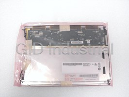
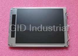
AU Optronics G084SN03 LCD Panel - 8.4" LCD Panel, screen diagonal 213.4 mm (8.4”),
active area 170.4 mm (H) x 127.8 mm (V), pixel H x V 800 mm (x3) x 600 mm, pixel
pitch 0.213 mm (H) x 0.213 mm (V), pixel arrangement R.G.B. vertical stripe, and
display mode is normally white. Typical white luminance (ICFL=4.6mA) [cd/m 2] 220
typical (center), contrast ratio is 500:1 typical, optical rise time/fall time
in msec is 10/25 typical, and nominal input Voltage VDD is +3.3 typical.
Part Number
G084SN03
Price
Request Quote
Manufacturer
AU OPTRONICS
Lead Time
Request Quote
Category
LCDS & PANEL DISPLAYS
Specifications
Active area [mm]
170.4 (H) x 127.8 (V)
AU Optronics
G084SN03
Contrast ratio
500:1 typical
Display mode
Normally white
Electrical Interface
1 channel LVDS
Nominal input Voltage VDD [Volt]
+3.3 typical
Optical rise time/fall time [msec]
10/25 typical
Physical size [mm]
203.0(W) x 142.5(H) x 5.7(D)
Pixel arrangement
R.G.B. vertical stripe
Pixel H x V
800 (x3) x 600
Pixel pitch [mm]
0.213( H) x 0.213 (V)
Screen diagonal [mm]
213.4 ( 8.4”)
Storage (shipping)
-20 to
Support color
Native 262K colors (RGB 6-bit driver)
Temperature range operating
0 to 50 degrees Celsius
Typical power consumption [Watt]
3.3 typical
Typical white luminance (ICFL
4.6mA) [cd/m 2]
Weight [grams]
215 ±10
Datasheet

Extracted Text
Version: 0.3 Total Pages: 23 Date: 2005/8/29 Product Functional Specification 8.4 inch SVGA Color TFT LCD Module Model Name: G084SN03 V.0 u ( ) Preliminary Specification ( ) Final Specification Note: This Specification is subject to change without notice. (C) Copyright AU Optroncis, Inc. 2005 All Right Reserved. G084SN03 V.0 No Reproduction and Redistribution Allowed. 8/9 I. Contents 1.0 Handling Precautions…………………………………………………..…4 2.0 General Description……………………………………………………….5 2.1 Display Characteristics 2.2 Functional Block Diagram 3.0 Absolute Maximum Ratings……………………………………………...7 4.0 Optical Characteristics……………………………………………………8 5.0 Signal Interface……………………………………………………………10 5.1 Connectors 5.2 Signal Pin 5.3 Signal Description 5.4 Signal Electrical Characteristics 5.5 Signal for Lamp Connector 6.0 Pixel Format Image………………………………………………………14 7.0 Parameter Guide Line CFL Inverter…………………………………...15 8.0 Interface Timing..…………………………………………………………16 8.1 Timing Characteristics 8.2 Timing Definition 8.3 Timing Chart 9.0 Power Consumption……………………………………………………..19 10.0 Power ON/OFF Sequence……………………………………………….20 11.0 Reliability Test Items…………………………………………………..…21 12.0 Packing Dimension…………………………………………………….…22 13.0 Mechanical Characteristic..……………………………………………..23 (C) Copyright AU Optroncis, Inc. 2005 All Right Reserved. G084SN03 V.0 No Reproduction and Redistribution Allowed. 8/9 II. Record of Revision Version and Date Page Old Description New Description Remark 0.1 2005/05/20 All N/A First draft 0.2 2005/08/09 5 N/A Add a discription of RoHs 0.3 2005/08/29 8 View angle 60/60/60/40 View angle 65/65/65/45 (C) Copyright AU Optroncis, Inc. 2005 All Right Reserved. G084SN03 V.0 No Reproduction and Redistribution Allowed. 8/9 1.0 Handing Precautions 1) Since front polarizer is easily damaged, pay attention not to scratch it. 2) Be sure to turn off power supply when inserting or disconnection from input connector. 3) Wipe off water drop immediately. Long contact with water may cause discoloration or spots. 4) When the panel surface is soiled, wipe it with absorbent cotton or other soft cloth. 5) Since the panel is made of glass, it may break or crack if dropped or bumped on hard surface. 6) Since CMOS LSI is used in this module, take care of static electricity and insure human earth when handling. 7) Do not open nor modify the module Assembly. 8) Do not press the reflector sheet at the back of the module to any directions. 9) In case if a module has to be put back into the packing container slot after once it was taken out from the container, do not press the center of the CCFL Reflector edge. Instead, press at the far ends of the CFL Reflector edge softly. Otherwise the TFT module may be damaged. 10) At the insertion or removal of the Signal Interface Connector, be sure not to rotate nor tilt the interface Connector of the TFT module. 11) After installation of the TFT module into an enclosure, do not twist nor bend the TFT module even momentary. At designing the enclosure, it should be taken into consideration that no bending/twisting forces are applied to the TFT module from outside. Otherwise the TFT module may be damaged. 12) Cold cathode fluorescent lamp in LCD contains a small amount of mercury. Please follow local ordinances or regulations for disposal. 13) Small amount of materials having no flammability grade is used in the LCD module should be supplied by power complied with requirements of Limited Power Source, or be applied exemption. 14) The LCD module is designed so that the CFL in it is supplied by Limited Current Circuit. Do not connect the CFL in Hazardous Voltage Circuit. (C) Copyright AU Optroncis, Inc. 2005 All Right Reserved. G084SN03 V.0 No Reproduction and Redistribution Allowed. 8/9 2.0 General Description This specification applies to the 8.4 inch color TFT LCD module B084SN03 V.0. This module is designed for General Display. The screen format is intended to support the SVGA (800(H) x 600(V)) screen and 262k colors (RGB 6-bits data driver). All input signals are LVDS interface compatible. The module does not contain an inverter card for backlight. This is an RoHs product. 2.1 Display Characteristics The following items are characteristics summary on the table under 25℃ condition: Items Unit Specifications Screen Diagonal [mm] 213.4 ( 8.4 ”) Active Area [mm] 170.4(H) x 127.8(V) Pixel H x V 800(x3) x 600 Pixel Pitch [mm] 0.213(H) x 0.213(V) Pixel Arrangement R.G.B. Vertical Stripe Display Mode Normally White 2 Typical White Luminance (ICFL=4.6 mA) [cd/m ] 220 Typ. (center) 500:1 Typ. Contrast Ratio Optical Rise Time/Fall Time [msec] 10/25 Typ. Nominal Input Voltage VDD [Volt] +3.3 Typ. Typical Power Consumption [Watt] 3.3 Typ (VDD line + VCFL line) Weight [Grams] 215 ±10 Physical Size [mm] 203.0(W) x 142.5(H) x 5.7(D) Electrical Interface 1 channel LVDS Support Color Native 262K colors (RGB 6-bit driver) Temperature Range [℃] Operating 0 to +50 [℃] Storage(Shipping) -20 to +60 (C) Copyright AU Optroncis, Inc. 2005 All Right Reserved. G084SN03 V.0 No Reproduction and Redistribution Allowed. 8/9 2.2 Functional Block Diagram The following diagram shows the functional block of the 8.4 inches Color TFT LCD Module: (C) Copyright AU Optroncis, Inc. 2005 All Right Reserved. G084SN03 V.0 No Reproduction and Redistribution Allowed. 8/9 3.0 Absolute Maximum Ratings Absolute maximum ratings of the module is as follows : Item Symbol Min Max Unit Conditions Logic/LCD Drive Voltage VDD -0.3 +4.0 [Volt] Input Voltage of Signal Vin -0.3 VDD+0.3 [Volt] CCFL Current ICFL 3 6 [mA] rms CCFL lgnition Voltage Vs 441 539 Vrms Operating Temperature TOP 0 +50 [℃] Note1 Operating Humidity HOP 8 90 [%RH] Note1 [℃] Storage Temperature TST -20 +60 Note1 Storage Humidity HST 5 90 [%RH] Note1 Vibration 1.0, 10-500 [G, Hz] 2hr/axis X,Y,Z Shock 220, 2 [G, ms] Half sine wave Note1:Maximum Wet-Bulb should be 39 ℃ and no condensation. (C) Copyright AU Optroncis, Inc. 2005 All Right Reserved. G084SN03 V.0 No Reproduction and Redistribution Allowed. 8/9 4.0 Optical Characteristics The optical characteristics are measured under stable conditions as follows under 25℃ condition: Item Unit Conditions Min. Typ. Max. Viewing Angle [degree] Horizontal (Right) - 65 - [degree] K = 10 (Left) 65 K:Contrast ratio [degree] Vertical (Upper) - 65 - [degree] K = 10 (Lower) 45 White Uniformity 9 Points - - 1.6 θ= 0° - Contrast ratio 300 500 Response Time [msec] Rising - 10 20 (Room Temp) [msec] - Falling 25 30 Color Red x 0.540 0.570 0.600 Chromaticity Red y 0.290 0.320 0.350 Coordinates(CIE) Green x 0.290 0.320 0.350 Green y 0.530 0.560 0.590 Blue x 0.120 0.150 0.180 Blue y 0.090 0.120 0.150 White x 0.280 0.310 0.340 White y 0.300 0.330 0.360 2 White Luminance [cd/m ] θ= 0° 200 220 - (ICFL 4.6 mA) (Center) (Center) (C) Copyright AU Optroncis, Inc. 2005 All Right Reserved. G084SN03 V.0 No Reproduction and Redistribution Allowed. 8/9 Note 1: Definition of white uniformity: White uniformity is calculated with the following formula. Luminance are measured at the following nine points (1~9). Maximum Brightness of nine points δ W Minimum Brightness of nine points (C) Copyright AU Optroncis, Inc. 2005 All Right Reserved. G084SN03 V.0 No Reproduction and Redistribution Allowed. 8/9 5.0 Signal Interface 5.1 Connectors Physical interface is described as for the connector on module. These connectors are capable of accommodating the following signals and will be following components. Connector Name / Designation For Signal Connector Manufacturer HIROSE Type / Part Number HRS DF 19K-20P-1H Mating Connector / Part Number HRS DF19G-20S-1C (WIRE TYPE)) Mating Connector / Part Number HRS DF19-20S-1F (FPC TYPE) Connector Name / Designation For Lamp Connector Manufacturer JST Type / Part Number BHSR-02VS-1 Mating Connector / Part Number SM02B-BHSS-1-TB 5.2 Signal Pin Pin No. Signal Name Pin No. Signal Name 1 VDD 2 VDD 3 GND 4 GND 5 RxIN0- 6 RxIN0+ 7 GND 8 RxIN1- 9 RxIN1+ 10 GND 11 RxIN2- 12 RxIN2+ 13 GND 14 CKIN- 15 CKIN+ 16 GND 17 NC 18 NC 19 GND 20 GND (C) Copyright AU Optroncis, Inc. 2005 All Right Reserved. G084SN03 V.0 No Reproduction and Redistribution Allowed. 8/9 5.3 Signal Description The module using a LVDS receiver. LVDS is a differential signal technology for LCD interface and high speed data transfer device. Transmitter shall be SN75LVDS84 (negative edge sampling) or compatible. Note:Input signals shall be low or Hi-Z state when VDD is off. Signal Name Description RxIN0-, RxIN0+ LVDS differential data input (Red0-Red5, Green0) RxIN1-, RxIN1+ LVDS differential data input (Green1-Green5, Blue0-Blue1) RxIN2-, RxIN2+ LVDS differential data input (Blue2-Blue5, Hsync, Vsync, DE) CKIN-, CKIN+ LVDS differential clock input VDD +3.3V Power Supply GND Ground NC No Connection (C) Copyright AU Optroncis, Inc. 2005 All Right Reserved. G084SN03 V.0 No Reproduction and Redistribution Allowed. 8/9 Signal Name Description +RED5 Red Data 5 (MSB) Red-pixel Data +RED4 Red Data 4 Each red pixel ’s brightness data consists of these +RED3 Red Data 3 6 bits pixel data. +RED2 Red Data 2 +RED1 Red Data 1 +RED0 Red Data 0 (LSB) Red-pixel Data +GREEN5 Green Data 5 (MSB) Green-pixel Data +GREEN4 Green Data 4 Each green pixel ’s brightness data consists of these +GREEN3 Green Data 3 6 bits pixel data. +GREEN2 Green Data 2 +GREEN1 Green Data 1 +GREEN0 Green Data 0 (LSB) Green-pixel Data +BLUE5 Blue Data 5 (MSB) Blue-pixel Data +BLUE4 Blue Data 4 Each blue pixel ’s brightness data consists of these +BLUE3 Blue Data 3 6 bits pixel data. +BLUE2 Blue Data 2 +BLUE1 Blue Data 1 +BLUE0 Blue Data 0 (LSB) Blue-pixel Data CLK Data Clock The typical frequency is 40MHz. The signal is used to strobe the pixel data and DE signals. All pixel data shall be valid at the falling edge when the DE signal is high. DE Display Timing This signal is strobed at the falling edge of CLK. When the signal is high, the pixel data shall be valid to be displayed. VSYNC Vertical Sync The signal is synchronized to CLK. HSYNC Horizontal Sync The signal is synchronized to CLK. Note:Output signals from any system shall be low or Hi-Z state when VDD is off. (C) Copyright AU Optroncis, Inc. 2005 All Right Reserved. G084SN03 V.0 No Reproduction and Redistribution Allowed. 8/9 5.4 Signal Electrical Characteristics Input signals shall be low or Hi-Z state when VDD is off. It is recommended to refer the specifications of SN75LVDS86(Texas Instruments) in detail. Signal electrical characteristics are as follows: Item Symbol Min. Typ. Max. Unit The differential level |VID| 0.1 - 0.6 V The common mode input ︱VID ︱ ︱ VID︱ VIC - 2.4- V voltage 2 2 The input setup time tsu 0.5 - - ns The input hold time thd 0.5 - - ns High-level input voltage VIAP 2.0 V Low-level input voltage V IAM 0.8 V Clock frequency CLK 31 68 MHz (C) Copyright AU Optroncis, Inc. 2005 All Right Reserved. G084SN03 V.0 No Reproduction and Redistribution Allowed. 8/9 5.5 Signal for Lamp connector Pin no. Symbol Function Remark 1 H CCFL power supply(H.V.) Cable color: Pink 2 L CCFL power supply(GND) Cable color: White 6.0 Pixel Format Image Following figure shows the relationship of the input signals and LCD pixel format: 1 2 799 800 R G B R G B R G B R G B 1st Line R G B R G B R G B R G B 600th Line (C) Copyright AU Optroncis, Inc. 2005 All Right Reserved. G084SN03 V.0 No Reproduction and Redistribution Allowed. 8/9 7.0 Parameter guide line for CFL inverter Parameter Min Typ Max Units Condition 2 White Luminance 200 220 - Cd/m CCFL current (ICFL) 3.0 4.6 - mArms Note1 CCFL Frequency (FCFL) 50 60 80 KHz Note4 CCFL Ignition Voltage (Vs) - - 1070(T=0 ℃) Vrms Note3 820(T=25 ℃) CCFL Voltage (Reference) 441 490 539 Vrms Note1 (VCFL) CCFL Power consumption - 2.3 - W Note2 (PCFL) Lamp Life Time 10,000 20,000 - Hr Note1, 5 Note1:T=25℃ Note2:Inverter should be designed with the characteristic of lamp. When you are designing the inverter, the output voltage of the inverter should comply with the following conditions. (1). The area under the positive and negative cycles of the waveform of the lamp current and lamp voltage should be area symmetric (the symmetric ratio should be larger than 90%). (2). There should not be any spikes in the waveform. (3). The waveform should be sine wave as possible. (4). Lamp current should not exceed the maximum value within the operating temperature (It is prohibited to over the maximum lamp current even if operated in the non-guaranteed temperature). When lamp current is over the maximum value for a long time, it may cause fire. Therefore, it is recommend that the inverter should have the current limit circuit. Note3:The inverter open voltage should be designed larger than the lamp starting voltage at o T=0 C, otherwise backlight may be blinking for a moment after turning on or not be able to turn on. The open voltage should be measured after ballast capacitor. If an inverter has shutdown function it should keep its open voltage for longer than 1 second even if lamp connector is open. Note4:Lamp frequency may produce interference with horizontal synchronous frequency and this may cause line flow on the display. Therefore lamp frequency shall be detached from the horizontal synchronous frequency and its harmonics as far as possible in order to avoid interference. Note5:Brightness (ICFL=4.6mA) to be decreased to the 50% of the initial value. (C) Copyright AU Optroncis, Inc. 2005 All Right Reserved. G084SN03 V.0 No Reproduction and Redistribution Allowed. 8/9 8.0 Interface Timings Basically, interface timing should match the VESA 800x600 /60Hz(VG901101) manufacturing guide line timing. 8.1 Timing Characteristics (a) DE mode Item Symbol Min. Typ. Max. Unit Remark Clock frequency Fck 38 40 48 MHz Horizontal blanking Thb1 50 256 500 Clk Vertical blanking Tvb1 10 28 150 Th (b) HV mode Item Symbol Min. Typ. Max. Unit Remark Clock frequency Fck 38 40 48 MHz Hsync period Th 850 1056 1300 Clk Hsync pulse width Thw 10 128 - Clk Hsync front porch Thf 15 40 - Clk Hsync back porch Thb 10 88 - Clk Hsync blanking Thb1 50 256 500 Clk Vsync period Tv 610 628 750 Th Vsync pulse width Tvw 1 4 - Th Vsync front porch Tvf 0 1 - Th Vsync blanking Tvb1 10 28 150 Th Hsync/Vsync phase shift Tvpd 2 320 - Clk Item Symbol Value Unit Description Horizontal display start The 218 Clk After falling edge of Hsync, counting 218clk, then getting valid data from 219th clk ’s data. Vertical display start Tve 25 Th After falling edge of Vsync, counting 25th, then getting 26th Th ’s data. (C) Copyright AU Optroncis, Inc. 2005 All Right Reserved. G084SN03 V.0 No Reproduction and Redistribution Allowed. 8/9 8.2 Timing Definition 1056 dot H-Sync 40 dot 88 dot 128 dot DE 800 dot 628H V-Sync 1H 23H 4H DE 28H 600H (C) Copyright AU Optroncis, Inc. 2005 All Right Reserved. G084SN03 V.0 No Reproduction and Redistribution Allowed. 8/9 8.3 Timing Chart (C) Copyright AU Optroncis, Inc. 2005 All Right Reserved. G084SN03 V.0 No Reproduction and Redistribution Allowed. 8/9 X,599 X,600 Invalid X,1 X,2 X,3 X,599 X,600 Invalid RGB Tvd Tvbl DE Tv Fck CLK 799,Y 800,Y invalid 800,Y invalid 1,Y 2,Y 3,Y RGB Thbl Thd DE Th (1 pixel / clock) 9.0 Power Consumption Input power specifications are as follows: Symbol Parameter Min Typ Max Units Condition VDD Logic/LCD Drive 3.0 3.3 3.6 V Voltage PDD VDD Power 0.76 W - - PDD Max VDD Power max 0.86 W - - IDD IDD Current 230 mArms Note 1 - - IDD Max IDD Current max 260 310 mArms Note 2 - V Power Ripple Voltage 100 mVp-p RP - - I Inrush Current 1500 mApeak RUSH - - Note 1: Effective value (mArms) at V = 3.3 V/25℃. CC Note 2: (C) Copyright AU Optroncis, Inc. 2005 All Right Reserved. G084SN03 V.0 No Reproduction and Redistribution Allowed. 8/9 10.0 Power ON/OFF Sequence VDD power and lamp on/off sequence is as follows. Interface signals are also shown in the chart. Signals from any system shall be Hi-Z state or low level when VDD is off. (C) Copyright AU Optroncis, Inc. 2005 All Right Reserved. G084SN03 V.0 No Reproduction and Redistribution Allowed. 8/9 11.0 Reliability Test Items Test item Test Condition Remark High temperature storage 60℃, 300Hrs Note 1, 2, 3 -20℃,300Hrs Low temperature storage Note 1, 2, 3 40℃, 90%RH, 300Hrs High temperature & high Note 1, 2, 3 humidity operation (No condensation) High temperature operation 50℃, 300Hrs Note 1, 2, 3 Low temperature operation 0℃, 300Hrs Note 1, 2, 3 -20℃~60℃ Temperature cycling Note 1, 2, 3 (non-operation) 1H, 10mins, 1H, 5cycles Electrostatic discharge 150 pF,150 Ω,10kV,1 second, 9 position Note 3 on the panel, 10 times each place (non-operation) Sweep:1G, 10H ~ 500H ~ 10H /2.5min Vibration Z Z Z Note 1, 2, 3 2 hours for each direction X, Y, Z (non-operation) Mechanical shock 50G/11ms, 220G/2ms, ±X, ±Y, ±Z Note 1, 2, 3 (non-operation) once for each direction Note 1: Evaluation should be tested after storage at room temperature for one hour. Note 2: There should be no change which might affect the practical display function when the display quality test is conducted under normal operating condition. Note 3: Judgement: 1.Function OK. 2.No serious image quality degradation. Display quality The display quality of the color TFT-LCD module should be in compliance with the AUO’s OQC inspection standard. Handling precaution The Handling of the TFT-LCD should be in compliance with the AUO’s handling principle standard. (C) Copyright AU Optroncis, Inc. 2005 All Right Reserved. G084SN03 V.0 No Reproduction and Redistribution Allowed. 8/9 12.0 Packing Dimension: LCD Module Anti-Static Bag NOTE : 1. Max. Capacity : 30 LCD Modules/Carton. EPP Cushion 2. Max. Weight : 12 Kg/Carton. 3. Meas : 600 mm*353mm*210mm. Carton (C) Copyright AU Optroncis, Inc. 2005 All Right Reserved. G084SN03 V.0 No Reproduction and Redistribution Allowed. 8/9 12.1 Label: (C) Copyright AU Optroncis, Inc. 2005 All Right Reserved. G084SN03 V.0 No Reproduction and Redistribution Allowed. 8/9 13.0 Mechanical Characteristic LCM Outline Dimension (C) Copyright AU Optroncis, Inc. 2005 All Right Reserved. G084SN03 V.0 No Reproduction and Redistribution Allowed. 8/9
Frequently asked questions
What makes Elite.Parts unique?

What kind of warranty will the G084SN03 have?
Which carriers does Elite.Parts work with?
Will Elite.Parts sell to me even though I live outside the USA?
I have a preferred payment method. Will Elite.Parts accept it?
Why buy from GID?

Quality
We are industry veterans who take pride in our work

Protection
Avoid the dangers of risky trading in the gray market

Access
Our network of suppliers is ready and at your disposal

Savings
Maintain legacy systems to prevent costly downtime

Speed
Time is of the essence, and we are respectful of yours
Related Products
Au Optronics G084SN05 8.4" TFT 800 x 600 SVGA LCD Module
Au Optronics M150XN04 15" TFT 1024 x 768 XGA LCD Module
AU Optronics M150XN07 V2 LCD Panel - 15" LCD Panel
AU OPTRONICS- T260XW02 V5-26" LCD Panel
AU Optronics T315XW01 V5 31.5" LCD Panel
AU Optronics T370XW01 V1 37" LCD Panel
Request a Quote

The quote request has been received
Close

Facing challenges or have inquiries? Feel free to contact us!
Call Us +1-469-283-2440
What they say about us
FANTASTIC RESOURCE
One of our top priorities is maintaining our business with precision, and we are constantly looking for affiliates that can help us achieve our goal. With the aid of GID Industrial, our obsolete product management has never been more efficient. They have been a great resource to our company, and have quickly become a go-to supplier on our list!
Bucher Emhart Glass
EXCELLENT SERVICE
With our strict fundamentals and high expectations, we were surprised when we came across GID Industrial and their competitive pricing. When we approached them with our issue, they were incredibly confident in being able to provide us with a seamless solution at the best price for us. GID Industrial quickly understood our needs and provided us with excellent service, as well as fully tested product to ensure what we received would be the right fit for our company.
Fuji
HARD TO FIND A BETTER PROVIDER
Our company provides services to aid in the manufacture of technological products, such as semiconductors and flat panel displays, and often searching for distributors of obsolete product we require can waste time and money. Finding GID Industrial proved to be a great asset to our company, with cost effective solutions and superior knowledge on all of their materials, it’d be hard to find a better provider of obsolete or hard to find products.
Applied Materials
CONSISTENTLY DELIVERS QUALITY SOLUTIONS
Over the years, the equipment used in our company becomes discontinued, but they’re still of great use to us and our customers. Once these products are no longer available through the manufacturer, finding a reliable, quick supplier is a necessity, and luckily for us, GID Industrial has provided the most trustworthy, quality solutions to our obsolete component needs.
Nidec Vamco
TERRIFIC RESOURCE
This company has been a terrific help to us (I work for Trican Well Service) in sourcing the Micron Ram Memory we needed for our Siemens computers. Great service! And great pricing! I know when the product is shipping and when it will arrive, all the way through the ordering process.
Trican Well Service
GO TO SOURCE
When I can't find an obsolete part, I first call GID and they'll come up with my parts every time. Great customer service and follow up as well. Scott emails me from time to time to touch base and see if we're having trouble finding something.....which is often with our 25 yr old equipment.
ConAgra Foods