

 Manufacturers
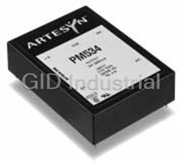
ARTESYN SXE15-48S2V5

Description
CONV DC/DC HIEFF 2.5VOUT 15W SMD
Part Number
SXE15-48S2V5
Price
Request Quote
Manufacturer
ARTESYN
Lead Time
Request Quote
Category
TBD
Datasheet


Extracted Text
CXE/SXE/SXN15 Application Note 116 1. Introduction 2 2. Models Features 2 3. General Description Electrical Description 2 Physical Construction 2 4. Features and Functions Wide Operating Temperature Range 3 Output Voltage Adjustment 3 Remote ON/OFF 3 Constant Switching Frequency 3 Current Limit and Short Circuit Protection 3 Output Overvoltage Protection 3 Input Undervoltage Protection 3 5. Safety Isolation 4 Input Fusing 4 6. EMC Conducted Emissions 4 Radiated Emissions 4 7. Use in a Manufacturing Environment Soldering Considerations 5 Reflow Considerations 5 Water Washing 5 ESD Control 5 8. Applications Optimum PCB Layout 6 Safe Area Of Operation 7 Optimum Thermal Performance 7 Remote ON/OFF Control 8 Specification for the Remote ON/OFF 8 Isolated Closure Remote ON/OFF Pin 8 Output Voltage Adjustment 8 Trim Behaviour of various models 10 Single Output Models (not including the SXE15-48S12) 10 SXE15-48S12 10 Dual Output Models 11 Output Capacitance 11 Reflected Ripple Current and Output Ripple and Noise Measurement 12 Parallel Operation 12 Compatability with ADM1070 Hot Swap Controller 12 Rev. 02 / 18 October 2002 CXE/SXE/SXN15 | Application Note 116 Rev. 02 3. General Description • Efficient topology utilising synchronous rectification, 87% typical at 5V 3.1 Electrical Description • Operating ambient temperature up to and The SXE15 power module is a DC/DC converter that operates over exceeding 70°C (natural convection). 100ºC an input voltage range of 33VDC to 75VDC and provides either one operation possible with derating or two isolated regulated DC outputs. The modules have a maximum power rating of 15W and excellent efficiencies are • Approved to EN60950, UL/cUL1950 achieved by optimal driving of the synchronous rectification stage. • Complies with ETS 300 019-1-3/2-3 • Complies with ETS 300 132-2 input voltage The standard feature set includes Remote ON/OFF and output trim and current requirements for maximum flexibility in distributed power applications. • Fully compliant with ETS 300 386-1 + Foreword Vin Input Filter Vo+ – Synchronous Rectifiers This application note covers the CXE15 (single), SXE15 (single and dual) and SXN15 (single and dual) series. The examples in this Current application note relate to the SXE15 product but can be assumed to Limit Vo – Remote On/Off be the same for all products across the series unless specified Control ON/OFF Feedback TRIM Adjustability otherwise. Secondary Control Primary 1. Introduction Control OVP Optocoupler OVP The SXE15 series is a new generation of DC/DC converters designed Isolation Barrier in response to the growing need for lower operating voltages and higher efficiencies. They offer unprecedented efficiency figures and a wide range of low output voltage solutions. In addition, automated manufacturing methods and an extensive Figure 1 - Electrical Block Diagram qualification program have produced one of the most reliable ranges of converters on the market. The DC input is filtered by an LC stage before it reaches the main power transformer. A current controlled PWM controller is used to provide a precisely regulated output voltage. The main power switch is a MOSFET running at a constant switching frequency of 2. Models approximately 265kHz. The SXE15 series comprises seven separate models as shown in The output voltage is sensed and compared with a secondary side Table 1. All popular integrated circuit operating voltages are covered reference and a compensated error signal is fed back via an by the range. optocoupler to the PWM controller. The secondary side trim pin allows the user to adjust the output voltage by connecting a resistor between trim and either the positive or negative output voltage pin. Model Input Voltage Output Voltage 3.2 Physical Construction SXE15-48S12* 33-75VDC 12V The SXE15 is constructed using a single multi-layer FR4 PCB. SMT SXE15-48S05 33-75VDC 5V components are placed on both sides of the PCB with, in general, SXE15-48S3V3 33-75VDC 3.3V the heavier power components mounted on the top side in order to optimise heat dissipation. SXE15-48S2V5 33-75VDC 2.5V SXE15-48S1V8 33-75VDC 1.8V The converter is sold as an open frame product and no case is provided. The open frame design has several advantages over SXE15-48D05-3V3** 33-75VDC 5V, 3.3V encapsulated closed devices. Among these advantages are: SXE15-48D3V3-2V5** 33-75VDC 3.3V, 2.5V *This model available in SXE series only • Cost: no encapsulation, case or associated process costs **There are no dual output models in the CXE range involved. • Thermals: the heat is removed from the heat generating Table 1 - Output Voltages components without heating more sensitive, less tolerant components such as opto-couplers. Features • Environmental: some encapsulants are not kind to the • Wide operating ambient temperature range of up to and exceeding environment and create problems in incinerators. Further more +70˚C with natural convection and 100ºC with derating open frame converters are more easily re-cycled. • Output voltage adjustability • Reliability: open Frame modules are more reliable for a number of • Primary-side controlled Remote ON/OFF reasons, such as better thermals and removal of TCE stresses • Constant switching frequency associated with encapsulants. • Brickwall overcurrent protection • Continuous short circuit protection • Input undervoltage protection 2 Application Note 116 Design Note 102 "Open Frame Low to Medium Power DC/DC Converter Modules" is available on the internet at http//www.artesyn.com/html/design_notes.html. Readers are Vout encouraged to familiarise themselves with its content. This paper details many of the advantages of open frame products over their cased and potted counterparts. The effective elimination of the encapsulant and case has been made possible by the use of modern automated manufacturing techniques and, in particular, the 100% use of SMT components and exceptionally high power conversion efficiencies. 100% Iout 4. Features and Functions 4.1 Wide Operating Temperature Range Figure 2 - Typical Brickwall V-I Characteristic The wide ambient temperature range of the SXE15 module is a consequence of its extemely high conversion efficiency and the None of the specifications are guaranteed when the unit is operated resultant low power dissipation. Operation from -40˚C to a maximum in an overcurrent condition. The unit can be operated continuously ambient temperature of up to and exceeding +70˚C at full rated in this condition, but its lifetime of the unit will be reduced. power is achieved without the requirement for heatsinks or forced air cooling. Derated operation is achieved at 100ºC ambient. Consult 4.6 Output Overvoltage Protection the factory for details. The clamped overvoltage protection (OVP) feature is used to protect the module and the user’s circuitry when a fault occurs in the main 4.2 Output Voltage Adjustment control loop. The unit is also protected in the event that the output The output voltage on all models is trimmable by -10% to +10% of is trimmed above the recommended maximum specification. the nominal output voltage. Details on how to trim all models are provided in the applications section of this document. The OVP circuit works by sensing the level of the primary bias voltage from the main transformer. This winding is voltage coupled 4.3 Remote ON/OFF to the secondary winding and can therefore detect any changes in The Remote ON/OFF function allows the unit to be controlled by an the voltage level at the output. When an OV condition is detected by external signal that puts the module into a low power dissipating this circuit the unit enters a max duty cycle mode, clamping the sleep mode. Examples of how this function may be employed are output voltage to the level determined in Table 2. detailed in the applications section of this document. 4.4 Constant Switching Frequency Output Voltage Clamp Level The switching frequency for all models is fixed at approximately 12V 15V 265kHz and is independent of line and load conditions. This makes 5V 6.0V the overall power system more predictable and greatly simplifies the design of the input filter required for EMC compliance. 3.3V 4.0V 2.5V 3.0V 4.5 Current Limit and Short Circuit Protection All models of the SXE15 have a built-in brickwall current limit 1.8V 2.2V function and full continuous short circuit protection. Thus, the V-I Table 2 - OVP Clamp Levels (output voltage - output current) characteristic will be almost vertical at the current limit inception point as shown in Figure 2. The current 4.7 Input Undervoltage Protection limit inception point depends on the input voltage and ambient The SXE15 series is fitted with a detection circuit at the input side temperature, and also has a parametric spread. For example, the that inhibits operation of the converter when the input voltage is inception point of the CXE15-48S05 is typically 120% and may go as below the normal operating range. The converter is disabled when high as 144% (See long form datasheet on our website for details). the input voltage is below 33V (typ). This UV trip protects against deep discharge of telecom batteries. The threshold has inherent hysteresis to provide immunity against slow ramping input voltages. The module operates in a low power dissipation mode when protected. 3 www.artesyn.com Load CXE/SXE/SXN15 | Application Note 116 Rev. 02 5. Safety 90 5.1 Isolation The SXE15 series has been designed in accordance with EN60950 80 and CAN/CSA-C22.2 No. 60950-00 and UL60950 ‘Safety of 70 Information Technology Equipment’. Class A 60 Avg Limit The SXE15 DC/DC converter is intended for inclusion in other Class B 50 equipment and the installer must ensure that it is in compliance with Avg limit all the requirements of the end application. 40 Series1 30 For many applications models with operational insulation will be sufficient provided that one pole of the output is connected to 20 protective earth. Units with operational isolation are less costly and 10 will have 1-2% higher efficiency than the equivalent model with basic 100KHz 1MHz 10MHz 100MHz isolation. The galvanic isolation is verified in an electric strength test during production; the test voltage between input and output is 1.5kVDC. Figure 3 - SXE15-48S3V3 Conducted Noise with Recommended Also, note that the flammability ratings of the terminal support Class B External Filter header blocks and internal plastic constructions meet UL94V-0. 5.2 Input Fusing In order to comply with safety requirements, the user must provide a fuse in the unearthed input line if an earthed input is used. The C y2 C reason for putting the fuse in the unearthed line is to avoid earth y4 R y2 being disconnected in the event of a failure. If an earthed input is Vin + Vo + + not being used, the fuse can be placed in either input line. A 2 Amp slow-blow/anti-surge 200V HRC (High Rupture Capacity) To LISN CXE/SXE/SXN15 fuse should be used for all models. C C x1 x2 – Vin – Vo – L x1 Ry 1 C y3 GND C y1 6. EMC The SXE15 has been designed to comply with the EMC requirements of ETSI 300 386-1. It meets the most stringent requirements of Table 5; "Public telecommunications equipment, locations other than telecommunication centres, High Priority of Service." Figure 4 - Recommended Class B Filter Conducted Emissions The part numbers for the components used are The required standard for conducted emissions is EN55022 (FCC given below: Part 15). The SXE15 Single has a substantial LC filter on board that greatly reduces conducted emissions. However, to meet Class A Cx1, ITW Paktron 4µF, 100V, SMT film capacitor, 405K100CS4 and Class B limits, an external filter should be connected to the Cx2, ITW Paktron 4µF, 100V, SMT film capacitor, 405K100CS4, converter's input. External filter components are required because of Cy1, Cy2, AVX 5.6nF, 1.5kV, 1812SC562KA1 space constraints on the 1" x 2" PCB. Additionally, having complete Cy3, Cy4, AVX 0.1µF, 100V, 12061C104KAT internal filtering would have removed the flexibility that end-users Ry1, Ry1, 5.6Ω resistor have to add a single filter to the input of all converters on a card, Lx1, Pulse Eng PO354 thereby reducing cost and space in the application. Radiated Emissions A typical conducted noise plot for the SXE15-48S3V3 is shown in The applicable standard is EN55022 Class B (FCC Part 15). Testing Figure 3 (average measurement). The filter circuit to achieve the DC/DC converters as a stand-alone component to the exact Class B standard is shown in Figure 4. All other models have similar requirements of EN55022 is very difficult, because the standard calls EMI plots and these are available on request. Class A filter for 1m leads to be attached to the input and output ports and information may also be obtained from Artesyn Technologies upon aligned such as to maximize the disturbance. In such a set-up it is request. possible to form a perfect dipole antenna and very few DC/DC converters would pass the test. 4 Application Note 116 However, the standard also states that ‘an attempt should be made to maximize the disturbance consistent with the typical application by varying the configuration of the test sample'. In addition, ETS 300 386-1 states that the testing should be carried out on the 221 enclosure. For most applications the signal input lines to the 183 converter should be less than 3 metres long and this is sufficient to 150 meet the requirements of the standard. 75 secs 87 The scans (measured at approx. 3 metres in an anechoic chamber) were taken at an accredited test site. The module 25 orientation, along with the height and polarisation of the Zone 1 Zone 2 Zone 3 Zone 4 Zone 5 Zone 6 Zone 7 antenna, was investigated to ensure that maximum emissions were 68 102 204 238 272 306 340 obtained. The test showed that the product meets the Class A 34 136 170 standard and these results are available from Artesyn Technologies TIME (secs.) on request Figure 5 - Recommended Reflow Profile for SXE15 and SXN15 7. Use in a Manufacturing Environment 7.3 Water Washing Where possible a no-clean solder paste system should be used for 7.1 Soldering Considerations solder attaching the SXE15 product onto application boards. The Large surface mount components typically require more solder paste SXE15 is suitable for water washing applications, because it does than smaller components to ensure a reliable solder joint. The not have entrapment areas where water and residues may become SXE15 series surface mount converters have been evaluated for trapped long term. However, the user must ensure that the drying solder joint reliability to MIL-STD-202F and IPC 610 Class B process is sufficient to remove all water from the converter after standards. This evaluation was completed on SXE15 and SXN15 washing - never power the converter unless it is fully dried. The 3 samples using 2.7mm of solder paste. The required volume can be user's process must clean the soldered assembly in accordance with achieved by printing 0.254mm (10mil) paste onto the recommended ANSI/J-STD-001. land pattern. 7.4 ESD Control Although this volume is recommended, tests have been conducted SXE15 units are manufactured in an ESD controlled environment and using lower volumes with successful results. Contact Artesyn supplied in conductive packaging to prevent ESD damage occurring Technologies for details. before or during shipping. It is essential that the units are unpacked and handled using an approved ESD control procedure. Failure to 7.2 Reflow Considerations do so could affect the lifetime of the converter. The gull-wing leads are plated with tin-lead to prevent corrosion and ensure good solderability. Eutectic solder typically melts at 183ºC. The lead temperatures must exceed this for a minimum of 30 seconds in order to to guarantee a reliable solder joint. The temperature of each gull-wing lead varies during reflow due to differences in internal components, PCB lands and connecting paths. Pin 1 is a good choice for conservative temperature measurement, because it is connected to heavy copper paths. Figure 5 shows the lead temperature of pin 1 during a typical recommended reflow profile. 5 www.artesyn.com TEMPERATURE ˚C 1.00 [25.40] 1.00 [25.40] CXE/SXE/SXN15 | Application Note 116 Rev. 02 vertically. This may result in reduced output power, particularly if 8. Applications there is no forced air present. 8.1 Optimum PCB Layout The recommended PCB layouts will not compromise the creepage Figures 6, 7, 8 and 9 show the optimum PCB layout with the 2 and clearance requirements discussed in the safety section of this recommended copper thickness of 2oz/ft or 70µm copper. The PCB application note. However, the end user must ensure that other acts as a heatsink and draws heat from the unit via conduction components and metal located in the vicinity of the SXE15 meet the through the pins and by radiation. The copper layer also acts as an 2 spacing requirements to which the system is approved. EMC shield. If the recommended layout or 2oz/ft copper isn’t used then the user needs to ensure that the hot-spot highlighted in the Note also that the recommended layouts do not guarantee system thermal section is kept within the recommended limits (see Section EMC compliance, since this depends upon the end application. 8.3). The hotspot must also be monitored if the unit is not mounted VIEW IS FROM TOP SIDE VIEW IS FROM TOP SIDE 1.91 [48.4] 2.00 0.77 [19.7] Min [50.80] 0.62 [15.8] Max 0.08 [2.00] 0.30 [7.5] Max Isolation 0.08 [2.0] Min +Vin +Vout -Vin 0.60 [15.1] Max -Vout 0.28 [7.0] Min See recommended land SEE RECOMMENDED HOLE PATTERN FOR OTHER DIMENSIONS pattern for dimensions THERMAL RELIEF IN CONDUCTOR PLANES THERMAL RELIEF IN CONDUCTOR PLANES REFERENCE IPC-D-275 SECTION 5.3.2.3 REFERENCE IPC-D-275 SECTION 5.3.2.3 ALL DIMENSIONS IN INCHES (mm) ALL DIMENSIONS IN INCHES (mm) ALL TOLERANCES ARE ±0.10 (0.004) ALL TOLERANCES ARE ±0.10 (0.004) Figure 8 - Optimum PCB Layout for EMC and Thermals Figure 6 - Optimum PCB Layout for EMC and Thermals for SXE15 on a single-sided PCB (including Keep-Out areas) for CXE15 on a double-sided PCB (including Keep-Out areas) Plot 1 of 2 VIEW IS FROM TOP SIDE VIEW IS FROM TOP SIDE 1.91 [48.4] 2.00 0.77 [19.7] Min [50.8] 0.62 [15.8] Max 0.08 [2.00] Isolation 0.30 [7.5] Max -Vin -Vout -Vin 0.08 [2.0] 0.40 [10.2] Min -Vout Max See recommended land 0.10 [2.5] Min SEE RECOMMENDED HOLE PATTERN FOR OTHER DIMENSIONS pattern for dimensions THERMAL RELIEF IN CONDUCTOR PLANES THERMAL RELIEF IN CONDUCTOR PLANES REFERENCE IPC-D-275 SECTION 5.3.2.3 REFERENCE IPC-D-275 SECTION 5.3.2.3 ALL DIMENSIONS IN INCHES (mm) ALL DIMENSIONS IN INCHES (mm) ALL TOLERANCES ARE ±0.10 (0.004) ALL TOLERANCES ARE ±0.10 (0.004) Figure 7 - Optimum PCB Layout for EMC and Thermals for Figure 9 - Optimum PCB Layout for EMC and Thermals SXN15 on a double-sided PCB (including Keep-Out areas) for SXN15 on a single-sided PCB (including Keep-Out areas) Plot 2 of 2 6 0.93 [23.5] Max 0.73 [18.5] Max Application Note 116 8.2 Safe Area of Operation The Safe Operating Area (SOA) of the SXE15 single output converter is shown in Figure 10 and that for the dual output model is shown in Figure 11. MAXIMUM ALLOWABLE CURRENT LINE (A) I According to Figure 10, the SXE15 single output model can deliver limit 2 I rated 2 the rated output current I provided the hotspot temperature (see rated Section 8.3) is within the prescribed limits. Note however that the SOA does not remain valid across the full trim range of the converter. Safe Operating For example, if the unit is trimmed up by 10%, the output current Area must be correspondingly derated so that the output power remains at 15W. The module will still deliver full rated output current when the output is trimmed down. I I rated 1 limit 1 CURRENT ON SECOND OUTPUT RAIL (A) Figure 11- Safe Operating Area (Dual Output Models) V out, nom 8.3 Optimum Thermal Performance Safe The SXE15 can operate in still air up to the maximum ambient Operating temperature indicated in Table 3 when the recommended PCB Area layouts shown in Section 8.1 are used. Natural convection is defined as <0.1m/s airflow (20CFM). The SXE15 series has also been characterised for operation when forced air cooling is available. Figure 12 shows how forced air cooling will allow operation of the I I rated limit SXE15-48S3V3 in a higher ambient (up to 85ºC) at full output power. OUTPUT CURRENT (A) A full range of plots is available in the long form data sheets. Operation up to 100ºC ambient is also possible with derating. Consult the factory for details. Figure 10 - Safe Operating Area (Single Output Models) Rated Ambient Model Temperature in absence According to Figure 11, the SXE15 dual output models can deliver of forced Air Cooling the rated output current I from either output if the other is at no- rated SXE15-48S12 70 load (0A), provided the hotspot temperature (See Section 8.3) is within the prescribed limits. If, as is most likely, both outputs are SXE15-48S05 65 loaded, the maximum allowable current line in Figure 11 must be SXE15-48S3V3 65 used as in the following example: SXE15-48S2V5 70 Consider output 1 is loaded 75%. The maximum allowed current on SXE15-48S1V8 70 output 2 is determined by drawing a horizontal line from the vertical SXE15-48D05-3V3 65 axis until it meets the maximum allowable current line. A vertical line is drawn from the intersection of the horizontal and the maximum SXE15-48D3V3-2V5 65 allowable current line until it meets the horizontal axis. The value this line intersects is the maximum allowed current on output 2 for a 75% Table 3 - Maximum Ambient at Full Power, Natural Convection loading on output 1. Note, however, that the SOA does not remain valid across the full trim range of the converter. For example, if the unit is trimmed up by 5 10%, the output current must be correspondingly derated. The 4.5 Natural module will still deliver full rated output current when the output is Convection Simulation 4 trimmed down. 100LFM 200LFM 3.5 300LFM 400LFM 3 2.5 2 1.5 25 35 45 55 65 75 85 AMBIENT TEMPERATURE (˚C) Figure 12 - Output Current vs. Ambient Temperature in Natural Convection and Airflow for SXE15-48S3V3 7 www.artesyn.com OUTPUT VOLTAGE (V) OUTPUT CURRENT (A) CURRENT ON MAIN OUTPUT RAIL (A) CXE/SXE/SXN15 | Application Note 116 Rev. 02 During airflow testing the SXE15 was mounted vertically, with air flowing lengthwise along the converter from the input to the output side as shown in Figure 13. Figure 16 - Hot Spot Location on SXN15 Single Figure 13 - Recommended Direction of Forced Air. Air Flow is from Input Pins to Output Pins on all Models In order to comply with Artesyn's derating criteria and relevant safety standards the temperature of the hotspot should never rise above The most accurate method of ensuring that the converter is 115˚C. operating within its guidelines in a chosen application is to measure the temperature of a hot-spot. There is one such position on the 8.3 Remote ON/OFF Control CXE15, SXE15 and SXN15. Its temperature depends on the input The Remote ON/OFF control feature allows the user to switch the line voltage, output load and the ambient temperature. This hot converter on and off when an appropriate signal is applied to the spot, the main transformer, is shown in Figures 14 to 16. remote pin. This is a primary referenced function that allows the converter be put in a low power dissipation sleep mode. 8.4 Specification for the Remote ON/OFF See signal electrical interface on the SXE15 Single and SXE15 Dual data sheets. 8.5 Isolated Closure Remote ON/OFF An isolated closure is a closure with both high and low impedance states that sinks current, but does not source current. For on/off control the closure is between the on/off pin and Vin-. This can be a device such as a mechanical switch, open collector transistor or opto-isolator. Vin+ Figure 14 - Hot Spot Location on CXE15 Single Ion/o Remote + On/Off SXE15 Remote VOn/Off On/Off RB RBE - Vin- Figure 17 - Isolated Closure using a Transistor Note that in the long form data sheet, that the maximum acceptable leakage current is 50µA. The isolation device should have a leakage current less than this value or the module may go into a low power 1 dissipation mode (enabled). Figure 15 - Hot Spot Location on SXE15 Single 8.7 Output Voltage Adjustment The output can be trimmed by ±10% by connecting an external resistor between the TRIM pin and either of the output voltage pins. The single and dual output models have different trim characteristics and will be considered in turn. 8 Application Note 116 Single output models: Dual output models: With an external resistor between TRIM and V +, (R ), the With an external resistor between TRIM and V + (See Figure 20) out ADJ_DOWN out2 output voltage setpoint decreases (See Figure 18). Conversely, the output voltage setpoint decreases. Conversely, connecting an connecting an external resistor between TRIM and V -, (R ), external resistor between TRIM and COM (See Figure 21) increases out ADJ_UP increases the output voltage setpoint (See Figure 19). the output voltage setpoint. In each case both output rails increase or decrease together. SXE15 SXE15 Single Dual Vout 1+ Vin+ Vo+ Vin+ Vout 2+ Vin- Vin- Vo- Com Trim Trim Control Control Figure 18 - Circuit Configuration to Decrease Output Voltage Figure 20 - Circuit Configuration to Decrease Output Voltage (Singles) (Duals) SXE15 SXE15 Dual Single Vout 1+ Vin+ Vo+ Vin+ Vout 2+ Vin- Vin- Vo- Com Trim Trim Control Control Figure 19 - Circuit Configuration to Increase Output Voltage Figure 21 - Circuit Configuration to Increase Output Voltage (Singles) (Duals) 9 www.artesyn.com CXE/SXE/SXN15 | Application Note 116 Rev. 02 8.3 Trim Behaviour of Various Models Note that when the output voltage is trimmed up by a certain percentage, the output current must be derated correspondingly so 8.3.1 Single Output Models (not including SXE15-48S12) that the maximum output power of 15W is not exceeded. The equations used to determine the value of the external resistor (specified in kΩ) required to obtain the desired output voltage are: Graphs of the required resistor for all models are shown in Figure 22 (trim up) and in Figure 23 (trim down). È ˘ (Vtrim_down -L)G Radj_ = down -H kW Í ˙ (Vout, nom- Vtrim_down) Î ˚ 6 1.10 Equation 1 - Resistor Required for Trim Down Operation S05 ÊÈ ˘ ˆ GL S3V3 Radj_ = up - H kW Í ˙ Á ˜ (Vtrim_up-L) - K Ë ¯ Î ˚ S2V5 5 1.10 S1V8 Equation 2 - Resistor Required for Trim Up Operation Where, Vout, nom is the nominal output voltage of the module Vtrim-down is the desired output voltage 4 (or Vtrim-up) 1.10 1 2 34 5 67 89 R is the resistor required to achieve the desired ADJ_DOWN INCREASE IN VOUT (%) (trimmed down) output voltage R is the resistor required to achieve the desired ADJ_UP (trimmed up) output voltage G,H are 5110 and 2050 respectively Figure 22 - Trim Up Resistance vs. Percentage Change in Output Voltage and the following parameters are defined for the following models (Single Models not including SXE15-48S12) only: Model K L 6 1.10 SXE15-48S05 2.5 2.5 SXN15-48S05 S05 5 SXE15-48S3V3 1.10 S3V3 2.06 1.24 SXN15-48S3V3 S2V5 SXE15-48S2V5 S1V8 1.29 1.235 SXN15-48S2V5 4 1.10 SXE15-48S1V8 0.585 1.232 SXN15-48S1V8 3 Example: 1.10 10 9 8 7 6 54 32 1 To trim up the SXE15-48S05 model by 10% to 5.5V the required external resistor is: DECREASE IN VOUT (%) Ê ˆ È ˘ 5110 2.5 () Í ˙ Á ˜ Radj_ = up - 2050 kW = 23.5kW Figure 23 - Trim Down ÁÍ ˙ ˜ (5.5-2.5) - 2.5 Resistance vs. Percentage Change in Output Voltage Ë ¯ Î ˚ (Single Models not including SXE15-48S12) To trim down the SXE15-48S3V3 model by 10% to 2.97V the required external resistor is 24.7kΩ. The same applies for the 8.3.2 SXE15-48S12 corresponding SXN models. The SXE15 also has a 12V single output version. The trim equations for the SXE15-48S12 are shown below and the trim curves are The trim equations for the CXE15 series are calculated using different illustrated in Figures 24 and 25. K and L values. The values of K and L for the CXE15 series are defined in the following table: 6.012 Vout,adj - 40.628 Radj _down = kW 10.. 261- 0 845 Vout,adj Model K L CXE15-48S05 2.5 2.5 Equation 3 - Resistor Required for Trim Down of SXE15-48S12 CXE15-48S3V3 0.82 2.5 CXE15-48S2V5 1.235 1.27 41.09 - 1.732 Vout,adj Radj _up = kW CXE15-48S1V8 0.56 1.25 0.845 Vout,adj - 10.26 Automated trim calculators for all single output models (including Equation 4 - Resistor Required for Trim Up of SXE15-48S12 SXE15-48S12, See Section 8.3.2) are available on www.artesyn.com/powerlab. 10 RESISTANCE (Ω) RESISTANCE (Ω) Application Note 116 D3V3-2V5 D05-3V3 6 1.10 160000 140000 120000 5 1.10 100000 80000 60000 4 1.10 40000 20000 0 3 1.10 23 45 6 7 8 9 10 12 3 45 6 7 89 INCREASE IN VOUT (%) INCREASE IN VOUT (%) Figure 24 - Trim up Figure 26 - Trim Up Resistor vs. Percentage Change in Output Resistor vs. Percentage Change in Output Voltage (12V Model) Voltage (Dual Models) D05-3V3 D3V3-2V5 6 1.10 160000 140000 5 1.10 120000 100000 80000 4 1.10 60000 40000 3 1.10 20000 0 100 02 4 6 8 10 98 7 65 4 3 21 DECREASE IN VOUT (%) DECREASE IN VOUT (%) Figure 25 - Trim down Figure 27 - Trim down Resistor vs. Percentage Change in Output Resistor vs. Percentage Change in Output Voltage (12V Model) Voltage (Dual Models) 8.3.3 Dual Output Models 8.8 Output Capacitance The trim behaviour of the dual output models is shown in Figures 26 The SXE15 series is been designed for stable operation without the and 27. The required trim resistor is determined by selecting the need for external capacitors at the input or output terminals when , desired percentage increase in V drawing a perpendicular line powered from a low impedance source. However, when powering out from this axis until it meets the revelant trim curve and then drawing loads with large dynamic current requirements, improved voltage a horizontal line from this intersection until it meets the vertical axis. regulation can be obtained by inserting decoupling capacitors as The desired resistance value is read off this axis. A trim calculator close as possible to the load. Low ESR ceramic capacitors will for the SXE15 duals is available on www.artesyn.com/powerlab. This handle high frequency current components, while tantalum tool is recommended for accurate estimation of the required trim capacitors can be used to handle the lower frequency dynamic resistor. current variations. Note that the absolute maximum value of output capacitance is 10,000µF. Please contact your local Artesyn Technologies representative if you wish to use larger values of output capacitance. 11 www.artesyn.com RESISTANCE (Ω) RESISTANCE (Ω) RESISTANCE (Ω) RESISTANCE (Ω) CXE/SXE/SXN15 | Application Note 116 Rev. 02 8.9 Reflected Ripple Current and Output Ripple and Noise Measurement The ADM1070 is a 6-pin SOT-23, negative voltage hot-swap The measurement set-up outlined in Figure 28 has been used for controller that allows a board to be safely inserted and removed from both input reflected/terminal ripple current and output voltage ripple a live backplane. This product is compatible with the and noise measurements on SXE15 series converters. When CXE/SXE/SXN15 family. measuring output ripple and noise, a 50Ω coaxial cable with a 50Ω The ADM1070 provides the following features: termination should be used to prevent impedance mismatch reflections disturbing the noise readings at higher frequencies. The • Inrush current is limited to a programmable value by controlling input ripple current measurement set-up is compatible with ETS 300 the gate voltage of an external N-channel pass transistor 386-1. • The pass transistor is turned off if the input voltage is less than the programmable under-voltage threshold or greater than the over-voltage threshold. A programmable electronic circuit breaker protects the system against shorts. Input Input reflected capacitor The UV/OV pin can be used to detect under-voltage and over-voltage ripple ripple current Lsource current conditions at the power supply input. The CXE/SXE/SXN15 already 4.7µF 12µH source 0.1µF tantalum impedance ceramic has in-built under-voltage protection to ensure that the unit does not draw power from the source for voltages less than approximately + 30V. Users should refer to the data sheet of the ADM1070 for details + Cext Vout on setting the required UVLO and OVLO trip levels. CXE/SXE/SXN15 Vsource 33µF < 0.7ΩESR electrolytic The ADM1070 features a current limiting function that protects capacitor - against short circuits or excessive supply currents. The flow of current through the load is monitored by measuring the voltage across the sense resistor, R . The action taken by the controller sense in the event of an input over-current condition will depend upon the severity of that condition. Please refer to the ADM1070 product datasheet on www.analog.com for details. Figure 28 - Reflected Ripple Current Measurement Set-up 8.11 Parallel Operation Because of the absence of an active current sharing feature, parallel operation of multiple SXE15 is not recommended. If unavoidable, Oring-diodes must be used to decouple the outputs. Droop resistors will support some passive current sharing. It should be noted that both measures will adversely affect the power conversion efficiency. 8.12 Compatability with ADM1070 Hot Swap Controller Inserting circuit boards into a live -48V backplane can cause large input transient currents when large capacitances are charged. These transient currents can cause glitches on the system power supply and permanently damage components on the board. To ensure that the input voltage is stable and within tolerance before being applied to the DC-DC converter, Artesyn Technologies recommends the use of a hot-swap controller, such as the ADM1070 from Analog Devices. This device controls harmful transient currents and ensures safe insertion or removal of the application board from a live backplane. System GND R1 R2 ADM1070 Remote Vo2+ C on/off Vo2- Trim2 Vin+ Vo1+ CXE/SXE/SXN15 Vo1- System Rsense Vin- Trim1 -Vin FET (e.g. -48V) Figure 29 - Inrush Current Control using ADM1070 12
Frequently asked questions
What makes Elite.Parts unique?

What kind of warranty will the SXE15-48S2V5 have?
Which carriers does Elite.Parts work with?
Will Elite.Parts sell to me even though I live outside the USA?
I have a preferred payment method. Will Elite.Parts accept it?










What they say about us
FANTASTIC RESOURCE
One of our top priorities is maintaining our business with precision, and we are constantly looking for affiliates that can help us achieve our goal. With the aid of GID Industrial, our obsolete product management has never been more efficient. They have been a great resource to our company, and have quickly become a go-to supplier on our list!
Bucher Emhart Glass
EXCELLENT SERVICE
With our strict fundamentals and high expectations, we were surprised when we came across GID Industrial and their competitive pricing. When we approached them with our issue, they were incredibly confident in being able to provide us with a seamless solution at the best price for us. GID Industrial quickly understood our needs and provided us with excellent service, as well as fully tested product to ensure what we received would be the right fit for our company.
Fuji
HARD TO FIND A BETTER PROVIDER
Our company provides services to aid in the manufacture of technological products, such as semiconductors and flat panel displays, and often searching for distributors of obsolete product we require can waste time and money. Finding GID Industrial proved to be a great asset to our company, with cost effective solutions and superior knowledge on all of their materials, it’d be hard to find a better provider of obsolete or hard to find products.
Applied Materials
CONSISTENTLY DELIVERS QUALITY SOLUTIONS
Over the years, the equipment used in our company becomes discontinued, but they’re still of great use to us and our customers. Once these products are no longer available through the manufacturer, finding a reliable, quick supplier is a necessity, and luckily for us, GID Industrial has provided the most trustworthy, quality solutions to our obsolete component needs.
Nidec Vamco
TERRIFIC RESOURCE
This company has been a terrific help to us (I work for Trican Well Service) in sourcing the Micron Ram Memory we needed for our Siemens computers. Great service! And great pricing! I know when the product is shipping and when it will arrive, all the way through the ordering process.
Trican Well Service
GO TO SOURCE
When I can't find an obsolete part, I first call GID and they'll come up with my parts every time. Great customer service and follow up as well. Scott emails me from time to time to touch base and see if we're having trouble finding something.....which is often with our 25 yr old equipment.
ConAgra Foods