

 Manufacturers
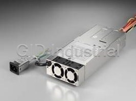
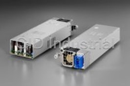
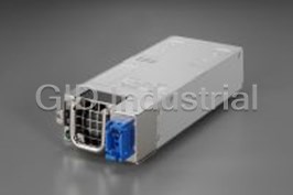
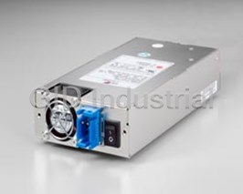
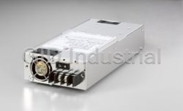
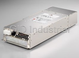
ZIPPY TECHNOLOGY H1M-6550P
Description
Zippy Technology H1M-6550P,1U Form,550W, Input Type Power Factor Correction (PFC), (DxWxH) 225/8.86 (mm/inch) x 100/3.94 (mm/inch) x 40.5/1.59 (mm/inch)
Part Number
H1M-6550P
Price
Request Quote
Manufacturer
ZIPPY TECHNOLOGY
Lead Time
Request Quote
Category
1U SINGLE POWER SUPPLY
Specifications
+12V1 VDC
Output Current Min:2 Output Current Max:44 Output Current Peak:- Regulation Load:±5% Regulation Line:±1% Output Ripple & Noise Max:100
+3.3 VDC
Output Current Min:1 Output Current Max:24 Output Current Peak:- Regulation Load:±5% Regulation Line:±1% Output Ripple & Noise Max:50
+5 VDC
Output Current Min:1 Output Current Max:30 Output Current Peak:- Regulation Load:±5% Regulation Line:±1% Output Ripple & Noise Max:50
+5 Vsb DC
Output Current Min:0.1 Output Current Max:4 Output Current Peak:- Regulation Load:±5% Regulation Line:±1% Output Ripple & Noise Max:50
-12 VDC
Output Current Min:0 Output Current Max:0.5 Output Current Peak:- Regulation Load:±5% Regulation Line:±1% Output Ripple & Noise Max:100
-5 VDC
Output Current Min:0 Output Current Max:0.5 Output Current Peak:- Regulation Load:±5% Regulation Line:±1% Output Ripple & Noise Max:100
Input (PS)
VOLTAGE: 90 ~ 264 VAC FULL RANGE FREQUENCY:47 ~ 63Hz INPUT CURRENT:7A/11A(RMS) FOR 230/115 VAC INRUSH CURRENT: 90A/130A MAX. FOR 115/230 VAC PER MODULE
Features
- Dielectric withstand: input/output 1500 vac for 1 minute
- Efficiency: 70% typical at 115v, at full load
- Emi noise filter: fcc class b, cispr 22 class b
- Hold up time: 16ms minimum
- Humidity: 10~90%rh
- Humidity: operating: 20%-95%, non-operating: 10%-95%
- Input to frame ground 1500 vac for 1 minute
- Meet iec-1000-3-2 class d
- Over power protection: 110~160% max.
- Over voltage protection: +5v-5.7v~6.5v, +3.3v-3.7v~4.1v, +12v-12.8v~13.9v
- Power good signal: on delay 100 ms to 500 ms, off delay 1ms
- Remarks: 85% is normal condition and 95% is with special coating process
- Safety: to meet ul/csa/tuv standard
- Temperature range: 0C---40C, -20C---80C
Datasheet

Extracted Text
Declaration of Conformity We, Manufacturer ZIPPY TECHNOLOGY CORP. 10F,No.50,MIN CHYUAN RD. SHIN-TIEN, TAIPEI HSIEN TAIWAN, R.O.C. declare that the product (description of the apparatus, system, installation to which it refers) SWITCHING POWER SUPPLY H1M-6550P is in conformity with (reference to the specification under which conformity is declared) in accordance with 2004/108/EC-EMC Directive ▓ ▓ EN 55022 : 2006+A1/2007 EN 61000-4-5 : 2006 Criteria B Information technology equipment Surge Immunity -Radio disturbance characteristics requirements -Limits and methods of measurement ▓EN 61000-4-6 : 2007 Criteria A ▓EN 55024 : 1998+A1/2001+A2/2003 Conducted Immunity Information technology equipment ▓EN 61000-4-8 : 1993+A1/2001 Criteria A -Immunity characteristics Power Frequency Magnetic -Limits and methods of measurement Field Immunity ▓EN 61000-4-2 : 2009 Criteria B ▓EN 61000-4-11 : 2004 Electrostatic discharge Dip Criteria B requirements "ESD" Interruptions Criteria C ▓EN 61000-4-3 : 2006+A1/2008 Criteria A Voltage Dip,interruptions Radiated, radio frequency Immunity requirements electromagnetic field ▓EN 61000-3-2 : 2006 ▓ EN 61000-4-4 : 2004 Criteria B Harmonic current Electrical fast transient requirements requirements "EFT" ▓ EN 61000-3-3 : 2008 Voltage fluctuations and flicker requirements Manufacturer Test-Lab Date : AUG,02,2010 Date : AUG,02,2010 Signature: Signature: Name: ZIPPY Name: ZIPPY MODEL : H1M-6550P REPORT NO. : 10080201 APPLICATION FOR CERTIFICATION ON Behalf Of ZIPPY TECHNOLOGY CORP. SWITCHING POWER SUPPLY Model# : H1M-6550P FCCID:N/A : PREPARED FOR ZIPPY TECHNOLOGY CORP. 10F,No.50,MIN CHYUAN RD. SHIN-TIEN, TAIPEI HSIEN TAIWAN, R.O.C REPORT BY: ZIPPY TECHNOLOGY CORP. 10F,No.50,MIN CHYUAN RD. SHIN-TIEN, TAIPEI HSIEN TAIWAN, R.O.C TEL: (02)2918-8512 : FAX (02)2913-4969 2 MODEL : H1M-6550P REPORT NO. : 10080201 TABLE OF CONTENTS Description Page 5 1. Test Report Certification…………………………………………………………….. 6 2. General Information………………………………………………………………….. 2.1 Production Description………………………………………………………………….…….. 6 2.2 Tested System Details……………………………………………………………….………... 7 2.2.1 Resistor Load…………………………………………………………………………….. 7 2.3 Test Methodology…………………………………………………………………………….. 7 2.4 Test Facility……………………………………………………………………………………. 7 8 3. Electronic-Magnetic Interference Test………………………………….…..…... 3.1. Conducted Power Line Test……………………………………………………………..….. 8 3.1.1 Test Equipments…………………………………………………………………………. 8 3.1.2 Block Diagram of Test Setup…………………………………………………………… 8 3.1.3 Conducted Powerline Emission Limit…………………………………………………. 9 3.1.4 EUT Configuration on Measurement…………………………………………………… 9 3.1.5 EUT Exercise Software…………………………………………………………….……. 9 3.1.6 Conducted Emission Data 9 ………………………………………………………….……. 3.2. Radiation Emission Test .........................................................……….............………… 11 3.2.1 Test Equipment ....................................................................……...............………... 11 3.2.2 Test Setup ...........................................................……................................………... 11 3.2.3 Radiated Emission Limited ....................................…….............................……….. 12 3.2.4 EUT Configuration ...................................................……..........................………... 13 3.2.5 Operating Condition of EUT .......................................…….......................………... 13 3.2.6 Radiated Emission Data .....................................................…….................……….. 13 3.2.7 Test Photo and Setup ..................................................…….................……………. 13 17 4. ESD Measurement…………………………………………………………………….. 4.1 Test Equipments……………………………………………………………………………….. 17 4.2 Test Setup………………………………………………………………………………….…… 17 4.2.1 Block Diagram of Connections between EUT and simulators………………………. 17 4.2.2 Test Setup of EUT…………………………………………………………………….….. 17 4.3 Severity Levels………………………………………………………………………………… 18 4.4 EUT Operating Condition…………………………………………………………………….. 18 4.5 Test Procedure………………………………………………………………………….……… 18 4.6 Test Method…………………………………………………………………….……….…….. 18 4.7 Test Result…………………………………………………………………………………….. 19 3 MODEL : H1M-6550P REPORT NO. : 10080201 TABLE OF CONTENTS Description Page 20 5. Radiated Susceptibility Measurement……………………………………………. 5.1 Test Equipment…………………………………………………………………………….…... 20 5.2 Block Diagram of Test Setup………………………………………………………………… 20 5.3 Severity Levels………………………………………………………………………….…….. 21 5.4 EUT Operating Condition…………………………………………………………………….. 21 5.5 Test procedure…………………………………………………………………….…….…….. 21 5.6 Test Method……………………………………………………………………………….…… 21 5.7 Test Result…………………………………………………………………………………….. 22 6.Electrical Fast Transient/Burst Measurement 23 ……………...………………….. 6.1 Test Equipment …………………………………………………………………………….… 23 6.2 Block Diagram of Test Setup………………………………………………………………… 23 6.3 Severity Levels ……………………………………………………………………………….. 23 6.4 EUT Operating Condition……………………………………………………………………. 24 6.5 Test procedure ……………………………………………………………………….……….. 24 6.6 Test Method 24 ……………………………………………………………………………………. 6.7 Test Result…………………………………………………………………………………….. 25 26 7. Harmonic Current Requirements ………………………………………………… 29 8. Voltage Fluctuation and Filcker Test…………………………………………….. 30 9. Surge Immunity Test…………………………………………………………………. 31 10. Conducted Immunity Test…………………………………………………………. 32 11. Voltage Dip,interruptions Immunity Test……………………………………... 33 12. Photographs…………………………………………………………………………… 37 13. EMI Reduction method during compliance Testing………………………… Appendix A Circuit diagram, block diagram, User Manual Appendix B Doc 4 MODEL : H1M-6550P REPORT NO. : 10080201 1. Test Report Certification : Applicant ZIPPY TECHNOLOGY CORP. : Manufacturer ZIPPY TECHNOLOGY CORP. : EUT Description Switching Power Supply : (A) FCC ID N/A : (B) Model No. H1M-6550P (C) Serial No. : N/A : (D) Power Supply 115Vac/60Hz,230Vac/50Hz MEASUREMENT PROCEDURE USED : EN 55024 RULES EN 55022 RULES THE DEVICE DESCRIBED ABOVE WAS TESTED BY ZIPPY SHIN JIUH CORP. TO DETERMINE THE SEVERITY LEVELS THE DEVICE CAN ENDURE AND ITS PERFORMANCE CRITERION. THE MEASUREMENT RESULTS ARE CONTAINED IN THIS TEST REPORT AND ZIPPY SHIN JIUH CORP. IS ASSUMED FULL RESPONSIBILITY FOR THE ACCURACY AND COMPLETENESS OF THESE MEASUREMENT. ALSO, THIS REPORT SHOWS THAT THE EUT TO BE TECHNICALLY COMPLIANT WITH THE EN STANDARD. : Test Dated AUG,02,2010 : Test Engineer a : Approve & Authorized Signer 5 MODEL : H1M-6550P REPORT NO. : 10080201 2. General Information 2.1 Production Description : Description Switching Power Supply : Model Number H1M-6550P : Applicant ZIPPY TECHNOLOGY CORP. 10F,No.50,MIN CHYUAN RD. SHIN-TIEN, : Address TAIPEI HSIEN TAIWAN, R.O.C : FCC ID N/A : Data Cable N/A : PowerCord Non-Shielded, detachable, 1.5m 6 MODEL : H1M-6550P REPORT NO. : 10080201 2.2 Tested System Details The FCC IDs for all equipment, plus descriptions of all cables used in the tested system (including inserted cards, which have grants) are: 2.2.1 Resistor Load Model Number : ELECTRONIC LOAD Serial Number : N/A FCC ID : N/A Manufacturer : ZIPPY Power : 550W 2.3 Test Methodology EMI Test: Both conducted and radiated testing were performed according to the procedures in EN 55022 Radiated testing was performed at an antenna to EUT distance of 10 meters. EMS Test: Performed according to procedures in EN 61000 series regulations. 2.4 Test Facility ZIPPY TECHNOLOGY CORP. 10F,No.50,MIN CHYUAN RD. SHIN-TIEN, TAIPEI HSIEN TAIWAN, R.O.C 7 MODEL : H1M-6550P REPORT NO. : 10080201 3. Electronic-Magnetic Interference Test 3.1 Conducted Power Line Test 3.1.1 TEST Equipment's The following test equipment's are used during the conducted power line tests: Item Instrument Manufacture Type No: Last Calibration 1 TEST RECEIVER ROHDE & SCHWARZ ESHS10 Mar.,2010 2 LISN ROHDE & SCHWARZ ENV4200 Jan.,2010 3 COMPUTER Acer Power8000 N/A 4 PRINTER EPSON 5700L N/A 5 SHIELDED ROOM 4.0M*3.0M*3M N/A 3.1.2 Block Diagram of Test Setup TO Transformer L.I.S.N Power Line Test Receive Pulse Limiter Personal Computer EUT Switch Power Supply Printer/Plotter Load (Active) Terminator L.I.S.N AC IN 8 MODEL : H1M-6550P REPORT NO. : 10080201 3.1.3 Conducted Powerline Emission Limit Maximum RF Line Voltage dB(uV) Frequency Class B MHz QUASI-PEAK AVERAGE 0.15 - 0.50 66-56 66-56 0.50 - 5.0 56 56 5.0 - 30 60 60 Remarks : In the Above Table, the tighter limit applies at the band edges. 3.1.4 EUT Configuration on Measurement The equipment's which is listed 3.2 are installed on Conducted Power Line Test to meet the Commission requirement and operating in a manner which tends to maximize its emission characteristics in a normal application. 3.1.5 EUT Exercise Software The EUT exercise program used during conducted testing was designed to exercise the EUT in a manner similar to a typical use. The exercise sequence is listed as below : 3.1.5.1 Setup the EUT and simulators as shown on 3.2. 3.1.5.2 Turn on the power of all equipment's. 3.1.6 Conducted Emission Data The measurement range of conducted emission which is from 0.15 MHz to 30 MHz was investigated. The initial step in collecting conducted data is a spectrum analyzer peak scan of the measurement range for all the test modes. Then the worst modes were reported the following data pages. 9 MODEL : H1M-6550P REPORT NO. : 10080201 Conducted Emission Data : : ℃ 26 DATE OF TEST AUG,02,2010 TEMPERATURE : :65% EUT SWITCH POWER SUPPLY HUMIDITY : : TEST MODE H1M-6550P DISPLAY PATTERN N/A Frequency Reading Level dBuV Limites MHz Line 1 Line 2 DBuV 4.58 37.29 45.62 56.00 4.64 37.25 45.34 56.00 4.74 35.52 43.98 56.00 Remark:All readings are Quasi-Peak values. 10 ZIPPY EMC LAB conduction test EUT: H1M-6550P SPS Manuf: ZIPPY TECH CO..LTD Op Cond: FULL LOAD Operator: Test Spec: EN 55022-- Class B Comment: Load Condition( 29 22 0.5 0.5 19 4) L220V Scan Settings (3 Ranges) Frequencies Receiver Settings Start Stop Step IF BW Detector M-Time Atten Preamp OpRge 150kHz 500kHz 2kHz 10kHz QP+AV 1msec Auto OFF 60dB 500kHz 5MHz 20kHz 10kHz QP+AV 1msec Auto OFF 60dB 5MHz 30MHz 50kHz 10kHz QP+AV 1msec Auto OFF 60dB Transducer No. Start Stop Name 1 9kHz 30MHz CEB Prescan Measurement: Detectors: X QP / + AV Meas Time: see scan settings Peaks: 8 Acc Margin: 25 dB EN_QP_B EN_AV_B dBµV 100 90 80 70 60 50 40 30 20 10 0 0.15 1.0 10.0 30.0 MHz PAGE 1 ZIPPY EMC LAB conduction test EUT: H1M-6550P SPS Manuf: ZIPPY TECH CO..LTD Op Cond: FULL LOAD Operator: Test Spec: EN 55022-- Class B Comment: Load Condition( 29 22 0.5 0.5 19 4) L220V Scan Settings (3 Ranges) Frequencies Receiver Settings Start Stop Step IF BW Detector M-Time Atten Preamp OpRge 150kHz 500kHz 2kHz 10kHz QP+AV 1msec Auto OFF 60dB 500kHz 5MHz 20kHz 10kHz QP+AV 1msec Auto OFF 60dB 5MHz 30MHz 50kHz 10kHz QP+AV 1msec Auto OFF 60dB Transducer No. Start Stop Name 1 9kHz 30MHz CEB Prescan Measurement: Detectors: X QP / + AV Meas Time: see scan settings Peaks: 8 Acc Margin: 25 dB Peak Search Results Frequency QP Level QP Limit QP Delta Phase PE MHz dBµV dBµV dB - - 0.282 41.13 60.76 19.63 N gnd 4.28 36.47 56.00 19.53 N gnd 4.36 35.89 56.00 20.11 N gnd 4.42 36.70 56.00 19.30 N gnd 4.5 37.47 56.00 18.53 N gnd 4.58 37.29 56.00 18.71 N gnd 4.64 37.25 56.00 18.75 N gnd 4.72 35.52 56.00 20.48 N gnd Frequency AV Level AV Limit AV Delta Phase PE MHz dBµV dBµV dB - - 0.21 37.64 53.21 15.57 N gnd 0.232 36.50 52.38 15.88 N gnd 0.266 36.40 51.24 14.84 N gnd 0.27 37.64 51.12 13.48 N gnd 0.28 36.82 50.82 14.00 N gnd 0.284 36.50 50.70 14.20 N gnd 0.498 30.75 46.03 15.28 N gnd 4.58 32.67 46.00 13.33 N gnd * limit exceeded Indicated Phase/PE shows Configuration of max. Emission PAGE 2 ZIPPY EMC LAB conduction test EUT: H1M-6550P SPS Manuf: ZIPPY TECH CO..LTD Op Cond: FULL LOAD Operator: Test Spec: EN 55022-- Class B Comment: Load Condition( 29 22 0.5 0.5 19 4) N220V Scan Settings (3 Ranges) Frequencies Receiver Settings Start Stop Step IF BW Detector M-Time Atten Preamp OpRge 150kHz 500kHz 2kHz 10kHz QP+AV 1msec Auto OFF 60dB 500kHz 5MHz 20kHz 10kHz QP+AV 1msec Auto OFF 60dB 5MHz 30MHz 50kHz 10kHz QP+AV 1msec Auto OFF 60dB Transducer No. Start Stop Name 1 9kHz 30MHz CEB Prescan Measurement: Detectors: X QP / + AV Meas Time: see scan settings Peaks: 8 Acc Margin: 25 dB EN_QP_B EN_AV_B dBµV 100 90 80 70 60 50 40 30 20 10 0 0.15 1.0 10.0 30.0 MHz PAGE 1 ZIPPY EMC LAB conduction test EUT: H1M-6550P SPS Manuf: ZIPPY TECH CO..LTD Op Cond: FULL LOAD Operator: Test Spec: EN 55022-- Class B Comment: Load Condition( 29 22 0.5 0.5 19 4) N220V Scan Settings (3 Ranges) Frequencies Receiver Settings Start Stop Step IF BW Detector M-Time Atten Preamp OpRge 150kHz 500kHz 2kHz 10kHz QP+AV 1msec Auto OFF 60dB 500kHz 5MHz 20kHz 10kHz QP+AV 1msec Auto OFF 60dB 5MHz 30MHz 50kHz 10kHz QP+AV 1msec Auto OFF 60dB Transducer No. Start Stop Name 1 9kHz 30MHz CEB Prescan Measurement: Detectors: X QP / + AV Meas Time: see scan settings Peaks: 8 Acc Margin: 25 dB Peak Search Results Frequency QP Level QP Limit QP Delta Phase PE MHz dBµV dBµV dB - - 4.44 42.33 56.00 13.67 N gnd 4.52 43.34 56.00 12.66 N gnd 4.58 45.62 56.00 10.38 N gnd 4.66 45.34 56.00 10.66 N gnd 4.74 43.98 56.00 12.02 N gnd 4.8 44.49 56.00 11.51 N gnd 4.88 43.83 56.00 12.17 N gnd 4.94 43.07 56.00 12.93 N gnd Frequency AV Level AV Limit AV Delta Phase PE MHz dBµV dBµV dB - - 0.286 38.80 50.64 11.84 N gnd 4.38 36.61 46.00 9.39 N gnd 4.52 35.27 46.00 10.73 N gnd 4.66 38.77 46.00 7.23 N gnd 4.74 36.68 46.00 9.32 N gnd 4.8 35.89 46.00 10.11 N gnd 4.88 34.97 46.00 11.03 N gnd 4.96 33.34 46.00 12.66 N gnd * limit exceeded Indicated Phase/PE shows Configuration of max. Emission PAGE 2 MODEL : H1M-6550P REPORT NO. : 10080201 3.2 Radiation Emission Test 3.2.1 Test Equipment The following test equipment's are used during the radiated emission test : Instrument Manufacture Type No: Last Calibration Spectrum Analyzer H.P 8594A May.,2010 Test Receiver IFR System A-7550 Jun.,2010 Preamplifier H.P 8447D May.,2010 Biconical Ant. Emco 3110 Jun.,2010 Log-Periodic Ant. Emco 3146 Jun.,2010 Dipole Antenna Emco 3121C May.,2010 3.2.2 Test Setup 3.2.2.1 Block Diagram of Connection between EUT and simulators Equipment under Test Load EUT: SWITCHING POWER SUPPLY 11 MODEL : H1M-6550P REPORT NO. : 10080201 3.2.2.2 Open Field Test Site - description The open field test site (OFTS) is designed to provide an environment in which repeatable tests of radiated emissions can be carried out. It consists of a flat elliptical area as shown in the diagram below. The equipment under test and the antenna are placed at the foci of the ellipse. The antenna height should be remotely adjustable from 1m to 4m. Measuring instrumentation should be outside the ellipse at the position shown or in a room under the ground plane. The whole or part of the site may be enclosed in an RF transparent building. For precompliance testing a 3m test site with a fixed height antenna (at 1.5-2m height) and no metallic ground plane may be used. This may be a clear area on a car park or a grass area but should be away from large metallic structures. 3.2.3 Radiated Emission Limit Class B Limits Frequency Distance Field Strength MHz Meter DB(uV/M) 30-230 3 40 230-1000 3 47 Remarks : 1. The tighter limit shall apply at the edge between two frequency bands. 2. Distance refers to the distance in meters between the measuring instrumentantenna and the closed point of any part of the device or system. 12 MODEL : H1M-6550P REPORT NO. : 10080201 3.2.4 EUT Configuration The equipment's which is listed 4.2.1 are installed on Radiated Emission Test to meet the Commission requirement and operating in a manner which tends to maximize its emission characteristics in a normal application. 3.2.5 Operation Condition of EUT Same as Conducted Power Line Test which is listed in 3.1.5 . 3.2.6 Radiated Emission Data The measurement range of radiated emission which is from 30 MHz to 1000 MHz was investigated. The initial step in collecting conducted data is a spectrum analyzer peak scan of the measurement range for all the test modes. Then the worst modes were reported the following data pages. 3.2.7 Test Photo and Setup ※During the radiated test, the power-supply has to test with chassis, which is not allowed to be operated stand-alone. (For user, final assembly has to comply with corresponding EMC-and safety-regulations.) 13 MODEL : H1M-6550P REPORT NO. : 10080201 Radiated Emission Data : : ℃ 26 DATE OF TEST AUG,02,2010 TEMPERATURE : : % 65 EUT SWITCH POWER SUPPLY HUMIDITY : : TEST MODE DISPLAY PATTERN N/A H1M-6550P Emission Level Frequency Limits Remark Horizontal (MHz) dBuV/m dBuV/m 53.9 14.7 40.0 57.7 16.9 40.0 397.1 21.9 47.0 14 MODEL : H1M-6550P REPORT NO. : 10080201 Radiated Emission Data : : ℃ 26 DATE OF TEST AUG,02,2010 TEMPERATURE : : % 65 EUT SWITCH POWER SUPPLY HUMIDITY : : TEST MODE DISPLAY PATTERN N/A H1M-6550P Emission Level Frequency Limits Remark Vertical (MHz) dBuV/m dBuV/m 37.9 19.7 40.0 52.7 22.1 40.0 59.1 20.9 40.0 15 MODEL : H1M-6550P REPORT NO. : 10080201 Horizontal Curve Vertical Curve 16 MODEL : H1M-6550P REPORT NO. : 10080201 4. ESD Measurement 4.1 Test Equipment The following test equipment's are used during the ESD test : Instrument Manufacture Type No: Last Calibration ESD Simulator system Keytek MZ-15/EC May.,2010 Electronic Load D-RAM Load-2000 N/A 4.2 Test Setup 4.2.1 Block Diagram of Connections between EUT and simulators ESD Simulator EUT Load system 4.2.2 Test Setup of EUT 17 MODEL : H1M-6550P REPORT NO. : 10080201 4.3 Severity Levels TEST VOLTAGE CONTACT TEST VOLTAGE AIR LEVEL DISCHARGE DISCHARGE 1 2KV 2KV 2 4KV 4KV 3 6KV 6KV 4 8KV 8KV X SPECIAL SPECIAL 4.4 EUT Operating Condition 1. Setup the EUT and Test Equipment as shown on 4.2 2. power on. 4.5 Test Procedure Air Discharge: This test was done above a non-conductive surfaces. The round discharge electrode about 30cm away will approach as fast as possible to touch test points of the EUT. Discharge happens before the contact. This procedure is repeated ten times on one selected location. 4.6 Test Method According to IEC 61000-4-2 18 MODEL : H1M-6550P REPORT NO. : 10080201 4.7 Test Result : :26℃ DATE OF TEST AUG,02,2010 TEMPERATURE : :65% EUT SWITCH POWER SUPPLY HUMIDITY : : TEST MODE H1M-6550P DISPLAY PATTERN N/A Item Amount of discharge Voltage Results +2KV Pass Contact discharge 500 -2KV Pass +4KV Pass Contact discharge 500 -4KV Pass +2KV Pass Air discharge 500 -2KV Pass +4KV Pass Air discharge 500 -4KV Pass +6KV Pass Air discharge 500 -6KV Pass +8KV Pass Air discharge 500 -8KV Pass ※Input Voltage : AC 230Vac/50Hz 19 MODEL : H1M-6550P REPORT NO. : 10080201 5. Radiated Susceptibility Measurement 5.1 Test Equipment The following test equipment's are used during the RS test : Instrument Manufacture Type No: Last Calibration Signal generator H.P 8657A Dec.,2009 Power amplifier A&R 100A100 Dec.,2009 Field strength meter A&R FM2000 Oct.,2009 Field strength sensor A&R EP2000 Oct.,2009 Power antenna A&R AT1080 Oct.,2009 5.2 Block Diagram of Test Setup Antennas-layout For the upper frequency range of 200 to 1000 MHz, antennas are the normal method of producing the required field strength. This is also carried out in an anechoic chamber or a screened room. If a screened room is used it must be damped . The anechoic chamber should be used for compliance testing, the screened room may be used for precompliance testing. The fields in the screened room will not be as uniform as those obtainable in an anechoic chamber and will also not be as repeatable. The EUT is placed on a non-conductive table, 0.8 m above the reference ground plane, which in many cases will be the floor of a screened room. According to the standards, the EUT should be oriented so that its most sensitive side is facing the antenna. In practice it can be difficult to decide beforehand which is the most sensitive side, and in most cases, a series of tests will be required with the EUT in several orientations. 20 MODEL : H1M-6550P REPORT NO. : 10080201 5.3 Severity Levels LEVEL FIELD STRENGTH V/M 1 1 2 3 3 10 X SPECIAL 5.4 EUT Operating Condition Same as section 4.4. 5.5 Test Procedure The EUT and load are placed on a table which is 0.8 meter above ground. The field sensor is also placed on the same table to monitor field strength from transmitting antenna. EUT is set 1 meter away from the transmitting antenna which is mounted on an antenna each time. The antenna is fixed 1 meter above ground. Both horizontal and vertical polarization of the antenna are set on measurement. In order to judge the EUT performance, a CCD camera is used to monitor EUT screen. All the scanning conditions are as follows : Condition of Test Remarks 1. Field Strength 3 V/M Level 2 2. Radiated Signal 80% Amplitude Modulated with a 1KHz Tone 3. Scanning Frequency 80 MHz-1 GHz 4. Sweep Time of Radiated 0.0015 Decade/s 5.6 Test Method According to IEC 61000-4-3 21 MODEL : H1M-6550P REPORT NO. : 10080201 5.7 Test Result : : ℃ 26 DATE OF TEST AUG,02,2010 TEMPERATURE : : % 65 EUT SWITCH POWER SUPPLY HUMIDITY : : TEST MODE H1M-6550P DISPLAY PATTERN N/A Frequency Range Position Polarity Field Strength Results (MHz) (Angle) (HorV) (V/M) ∘ 80-1000 0 (Front) H 3 Pass ∘ 80-1000 90 (Right) H 3 Pass ∘ 80-1000 180 (Back) H 3 Pass 80-1000 270∘ (Left) H 3 Pass 0∘ 80-1000 (Front) V 3 Pass ∘ 80-1000 90 (Right) V 3 Pass ∘ 80-1000 180 (Back) V 3 Pass 80-1000 270∘ (Left) V 3 Pass : Test Result Criteria A 22 MODEL : H1M-6550P REPORT NO. : 10080201 6. Electrical Fast Transient / Burst Measurement 6.1 Test Equipment The following test equipment's are used during the EFT tests : Instrument Manufacturer Type No. Last Calibration Fast Transient / Burst enerator Keytek EMCpro May.,2010 6.2 Block Diagram of Test Setup 6.3 Severity Levels Open Circuit Output Test Voltage +/- 10% Level On power supply lines 1 0.5KV 2 1KV 3 2KV 4 4KV X SPECIAL 23 MODEL : H1M-6550P REPORT NO. : 10080201 6.4 EUT Operation Condition Same as section 4.4. 6.5 Test Procedure The EUT and its load are placed on a table which is 0.8 meter above a metal ground plane measured 1m*1m min. And 0.65 mm thick min. And projected beyond the EUT by at least 0.1m on all sides. The EUT is away from the walls of the test AC power line test is as follows: For Ac power line test: The EUT is connected to the power mains through a coupling device that directly couples the EFT interference signal. Each of the Line and Neutral conductor is impressed with burst noise for 1 min. 6.6 Test Method According to IEC 61000-4-4. 24 MODEL : H1M-6550P REPORT NO. : 10080201 6.7 Test Result : : ℃ 26 DATE OF TEST AUG,02,2010 TEMPERATURE : :65% EUT SWITCH POWER SUPPLY HUMIDITY : : TEST MODE H1M-6550P DISPLAY PATTERN N/A Inject time Inject Line Voltage KV Inject Method Result (sec) L1 +/-1 60 Direct Pass L2 +/-1 60 Direct Pass PE +/-1 60 Direct Pass L1-L2 +/-1 60 Direct Pass L1-PE +/-1 60 Direct Pass L2-PE +/-1 60 Direct Pass L1,L2-PE +/-1 60 Direct Pass ※Input Voltage : AC 230Vac/50Hz 25 MODEL : H1M-6550P REPORT NO. : 10080201 7. Harmonic Current Test : : ℃ 26 DATE OF TEST AUG,02,2010 TEMPERATURE : : % 65 EUT SWITCH POWER SUPPLY HUMIDITY : : TEST MODE DISPLAY PATTERN N/A H1M-6550P Reading Leve A Reading Leve A Item Item A Limites A Limites 1 3.062 3 0.188 2.300 5 0.054 1.140 7 0.042 0.770 9 0.035 0.400 11 0.027 0.330 13 0.019 0.210 15 0.010 0.150 17 0.005 0.132 19 0.004 0.118 21 0.003 0.107 23 0.002 0.098 25 0.001 0.090 27 0.002 0.083 29 0.005 0.078 31 0.009 0.073 33 0.010 0.068 35 0.010 0.064 37 0.006 0.061 39 0.001 0.058 26 MODEL : H1M-6550P REPORT NO. : 10080201 27 MODEL : H1M-6550P REPORT NO. : 10080201 28 MODEL : H1M-6550P REPORT NO. : 10080201 8. Voltage Fluctuation And Flicker Test : : ℃ 26 DATE OF TEST AUG,02,2010 TEMPERATURE : : % 65 EUT SWITCH POWER SUPPLY HUMIDITY : : TEST MODE DISPLAY PATTERN N/A H1M-6550P Item Reading Limit Result Pst 0.000 1.00 Pass P1t 0.000 0.65 Pass Dc (%) 0.000 3.00 Pass Dmax (%) 0.000 4.00 Pass Dt (%) 0.000 0.20 Pass 29 MODEL : H1M-6550P REPORT NO. : 10080201 9. Surge Immunity Test : : ℃ 26 DATE OF TEST AUG,02,2010 TEMPERATURE : : % 65 EUT SWITCH POWER SUPPLY HUMIDITY : : TEST MODE DISPLAY PATTERN N/A H1M-6550P Wavefor Voltage Output:LC Phs Ref Phs Ang Tests Delay Result 12 Ohm -2000V MAINS:L1/PE L1 0 deg. 5 60 sec Pass 12 Ohm -2000V MAINS:L1/PE L1 90 deg. 5 60 sec Pass 12 Ohm -2000V MAINS:L1/PE L1 270 deg. 5 60 sec Pass 12 Ohm 2000V MAINS:L1/PE L1 0 deg. 5 60 sec Pass 12 Ohm 2000V MAINS:L1/PE L1 90 deg. 5 60 sec Pass 12 Ohm 2000V MAINS:L1/PE L1 270 deg. 5 60 sec Pass 12 Ohm -2000V MAINS:L2/PE L1 0 deg. 5 60 sec Pass 12 Ohm -2000V MAINS:L2/PE L1 90 deg. 5 60 sec Pass 12 Ohm -2000V MAINS:L2/PE L1 270 deg. 5 60 sec Pass 12 Ohm 2000V MAINS:L2/PE L1 0 deg. 5 60 sec Pass 12 Ohm 2000V MAINS:L2/PE L1 90 deg. 5 60 sec Pass 12 Ohm 2000V MAINS:L2/PE L1 270 deg. 5 60 sec Pass 2 Ohm -1000V MAINS:L1/L2 L1 0 deg. 5 60 sec Pass 2 Ohm -1000V MAINS:L1/L2 L1 90 deg. 5 60 sec Pass 2 Ohm -1000V MAINS:L1/L2 L1 270 deg. 5 60 sec Pass 2 Ohm 1000V MAINS:L1/L2 L1 0 deg. 5 60 sec Pass 2 Ohm 1000V MAINS:L1/L2 L1 90 deg. 5 60 sec Pass 2 Ohm 1000V MAINS:L1/L2 L1 270 deg. 5 60 sec Pass 30 MODEL : H1M-6550P REPORT NO. : 10080201 10. Conducted Immunity Test : : ℃ 26 DATE OF TEST AUG,02,2010 TEMPERATURE : :65% EUT SWITCH POWER SUPPLY HUMIDITY : : TEST MODE H1M-6550P DISPLAY PATTERN N/A Frequency Range Polarity Field Strength Results (MHz) (HorV) (V/M) 0.15-80 H 3 Pass : INJECTION TYPE DIRECT CDN Type M3 TEST CONDITION:Step:1% Dwell Time : 3sec Test result:Criteria A 31 MODEL : H1M-6550P REPORT NO. : 10080201 11. Voltage Dip, Interruptions Immiunity Test : : ℃ 26 DATE OF TEST AUG,02,2010 TEMPERATURE : :65% EUT SWITCH POWER SUPPLY HUMIDITY : : TEST MODE H1M-6550P DISPLAY PATTERN N/A Test Phase Duration Reduction Performance Result Voltage % Angle (Periods) Required Observation 0 deg. 0.5 B A Pass 90 deg. 0.5 B A Pass >95% 180 deg. 0.5 B A Pass 270 deg. 0.5 B A Pass 0 deg. 25 C C Pass 90 deg. 25 C C Pass AC 115V 30% 180 deg. 25 C C Pass 270 deg. 25 C C Pass 0 deg. 250 C C Pass 90 deg. 250 C C Pass >95% 180 deg. 250 C C Pass 270 deg. 250 C C Pass 0 deg. 0.5 B A Pass 90 deg. 0.5 B A Pass >95% 180 deg. 0.5 B A Pass 270 deg. 0.5 B A Pass 0 deg. 25 C A Pass 90 deg. 25 C A Pass AC 230V 30% 180 deg. 25 C A Pass 270 deg. 25 C A Pass 0 deg. 250 C C Pass 90 deg. 250 C C Pass >95% 180 deg. 250 C C Pass 270 deg. 250 C C Pass 32 MODEL : H1M-6550P REPORT NO. : 10080201 12. Photographs 1.Front view of Power Supply 2.Back view of Power Supply 33 MODEL : H1M-6550P REPORT NO. : 10080201 3.Component side of Mainboard 4.Solder side of Mainboard 34 MODEL : H1M-6550P REPORT NO. : 10080201 5.Inside view of Power Supply 6.Inside view of Power Supply 35 MODEL : H1M-6550P REPORT NO. : 10080201 7.Test view 36 MODEL : H1M-6550P REPORT NO. : 10080201 13. EMI Reduction Method During Compliance Testing 1.No modification was made during test. 37
Frequently asked questions
What makes Elite.Parts unique?

What kind of warranty will the H1M-6550P have?
Which carriers does Elite.Parts work with?
Will Elite.Parts sell to me even though I live outside the USA?
I have a preferred payment method. Will Elite.Parts accept it?
Why buy from GID?

Quality
We are industry veterans who take pride in our work

Protection
Avoid the dangers of risky trading in the gray market

Access
Our network of suppliers is ready and at your disposal

Savings
Maintain legacy systems to prevent costly downtime

Speed
Time is of the essence, and we are respectful of yours
Related Products
Zippy Technology DGIN-6350F,DC N + 1 Form,350W, Input Type DC -48V, (DxWxH) 250/9.84 (mm/inch) x 79/...
Zippy DMIN-6220F Power Supply - Redundant Module 220W
Zippy Technology DP1A-6250F,DC 1U Form,250W, Input Type DC -48V, (DxWxH) 205/8.07 (mm/inch) x 100/3....
Zippy Technology DP1H-6350F,DC 1U Form,350W, Input Type DC -48V, (DxWxH) 225/8.86 (mm/inch) x 100/3....
550W VOLTAGE: 90 ~264 VAC FULL RANGE FREQUENCY: 47~63Hz INPUT CURRENT: 6A(RMS) FOR 230 VAC ...
550W VOLTAGE: 90 ~264 VAC FULL RANGE FREQUENCY: 47~63Hz INPUT CURRENT: 6A(RMS) FOR 230 VAC ...
Request a Quote

The quote request has been received
Close

Facing challenges or have inquiries? Feel free to contact us!
Call Us +1-469-283-2440
What they say about us
FANTASTIC RESOURCE
One of our top priorities is maintaining our business with precision, and we are constantly looking for affiliates that can help us achieve our goal. With the aid of GID Industrial, our obsolete product management has never been more efficient. They have been a great resource to our company, and have quickly become a go-to supplier on our list!
Bucher Emhart Glass
EXCELLENT SERVICE
With our strict fundamentals and high expectations, we were surprised when we came across GID Industrial and their competitive pricing. When we approached them with our issue, they were incredibly confident in being able to provide us with a seamless solution at the best price for us. GID Industrial quickly understood our needs and provided us with excellent service, as well as fully tested product to ensure what we received would be the right fit for our company.
Fuji
HARD TO FIND A BETTER PROVIDER
Our company provides services to aid in the manufacture of technological products, such as semiconductors and flat panel displays, and often searching for distributors of obsolete product we require can waste time and money. Finding GID Industrial proved to be a great asset to our company, with cost effective solutions and superior knowledge on all of their materials, it’d be hard to find a better provider of obsolete or hard to find products.
Applied Materials
CONSISTENTLY DELIVERS QUALITY SOLUTIONS
Over the years, the equipment used in our company becomes discontinued, but they’re still of great use to us and our customers. Once these products are no longer available through the manufacturer, finding a reliable, quick supplier is a necessity, and luckily for us, GID Industrial has provided the most trustworthy, quality solutions to our obsolete component needs.
Nidec Vamco
TERRIFIC RESOURCE
This company has been a terrific help to us (I work for Trican Well Service) in sourcing the Micron Ram Memory we needed for our Siemens computers. Great service! And great pricing! I know when the product is shipping and when it will arrive, all the way through the ordering process.
Trican Well Service
GO TO SOURCE
When I can't find an obsolete part, I first call GID and they'll come up with my parts every time. Great customer service and follow up as well. Scott emails me from time to time to touch base and see if we're having trouble finding something.....which is often with our 25 yr old equipment.
ConAgra Foods