®
CompactPCI
ZT 6501
ZT 6501
®®
Hardware User Manual
ÛZIATECH
ProcessorCPU Board with Mobile Pentium
ProcessorCPU Board with Mobile Pentium
CONTENTS
WHAT'S IN THIS MANUAL? ....................................................................................................................... 6
1. CPU INTRODUCTION.............................................................................................................................. 8
PRODUCT DEFINITION.................................................................................................................. 8
FEATURES OF THE ZT 6501 .........................................................................................................9
DEVELOPMENT CONSIDERATIONS .......................................................................................... 10
FUNCTIONAL BLOCKS ................................................................................................................ 10
COMPACTPCI BUS INTERFACE .................................................................................... 12
PENTIUM PROCESSOR.................................................................................................. 12
INTEL 430TX PCISET INTERFACE CHIP....................................................................... 12
DC/DC CONVERTERS..................................................................................................... 12
MEMORY AND I/O ADDRESSING .................................................................................. 13
10/100 MBIT ETHERNET INTERFACE ........................................................................... 13
SERIAL I/O ....................................................................................................................... 13
INTERRUPTS ................................................................................................................... 14
COUNTER/TIMERS.......................................................................................................... 14
DMA .................................................................................................................................. 15
WATCHDOG TIMER ........................................................................................................ 15
REAL-TIME CLOCK ......................................................................................................... 15
KEYBOARD CONTROLLER ............................................................................................ 16
PS/2 MOUSE CONTROLLER .......................................................................................... 16
UNIVERSAL SERIAL BUS (USB) .................................................................................... 16
IEEE 1284 PARALLEL PORT/PRINTER INTERFACE .................................................... 16
OPTIONAL EIDE INTERFACE......................................................................................... 17
OPTIONAL FLOPPY DRIVE INTERFACE....................................................................... 17
SOFTWARE...................................................................................................................... 17
2. RPIO INTRODUCTION........................................................................................................................... 20
PRODUCT DEFINITION................................................................................................................ 20
FEATURES OF THE ZT 4600 RPIO TRANSITION BOARD ........................................................ 20
ZT 4600 FUNCTIONAL BLOCKS.................................................................................................. 21
REAR-PANEL I/O ............................................................................................................. 21
MULTI-I/O ......................................................................................................................... 21
EIDE INTERFACE ............................................................................................................ 22
3. GETTING STARTED .............................................................................................................................. 23
UNPACKING.................................................................................................................................. 23
WHAT'S IN THE BOX?.................................................................................................................. 23
ZT 6501 CPU BOARD SYSTEM REQUIREMENTS ..................................................................... 23
MEMORY AND I/O CONFIGURATION......................................................................................... 24
MEMORY CONFIGURATION .......................................................................................... 24
I/O CONFIGURATION...................................................................................................... 24
ZT 4600 RPIO SYSTEM REQUIREMENTS.................................................................................. 27
CONNECTORS ............................................................................................................................. 27
SWITCHES AND CUTTABLE TRACES........................................................................................ 27
BIOS SETUP.................................................................................................................................. 27
BIOS SETUP SCREEN .................................................................................................... 28
SYSTEM CONFIGURATION OVERVIEW ....................................................................... 28
OPERATING SYSTEM INSTALLATION .......................................................................... 29
4. CONFIGURATION.................................................................................................................................. 30
SETUP AND OPERATION ............................................................................................................ 30
DRAM INSTALLATION AND REMOVAL OVERVIEW.................................................................. 30
DRAM REMOVAL............................................................................................................. 30
DRAM INSTALLATION..................................................................................................... 31
2
Contents
DIP SWITCH SETTINGS AND LOCATIONS ................................................................................ 31
DIP SWITCH DESCRIPTIONS...................................................................................................... 33
SW1-1 (BIOS RECOVERY DEVICE ENABLE)................................................................ 33
SW1-2 (FLASH WRITE PROTECT)................................................................................. 33
SW1-3, SW1-4 (CMOS CLEAR / BATTERY BACKUP) ................................................... 34
SW3-2-SW3-4 (SOFTWARE ID INPUTS 0-2).................................................................. 35
CUTTABLE TRACE OPTIONS AND LOCATIONS ....................................................................... 35
CT1 (BACKPLANE JTAG CONNECTOR)........................................................................ 38
CT2 (CORE DC-DC SHARE CIRCUITRY) AND CT12 (INTERFACE DC-DC SHARE
CIRCUITRY) ..................................................................................................................... 38
CT6-CT10, CT20-CT24 (CPU INTERFACE VOLTAGE SELECT) .................................. 38
CT11, CT17, CT18 (CPU SPEED MULTIPLIER SETTINGS).......................................... 39
CT13 (VOLTAGE MONITOR)........................................................................................... 40
CT15 (SOFTWARE RESET CONTROL).......................................................................... 40
CT16 (FAN VOLTAGE SELECT) ..................................................................................... 40
CT19 (SERIAL RING WAKE-UP) ..................................................................................... 40
CT25-CT29 (BOARD REVISION)..................................................................................... 41
CT30 (REAR PANEL ETHERNET ENABLE) ................................................................... 41
R1-R5 (GEOGRAPHICAL ADDRESSING) ...................................................................... 41
R106-R107 (CONNECT CHASSIS GROUND TO LOGIC GROUND)............................. 41
5. COMPACTPCI INTERFACE .................................................................................................................. 42
COMPACTPCI OVERVIEW .......................................................................................................... 42
INTENDED APPLICATIONS ......................................................................................................... 42
APPLICABLE DOCUMENTS......................................................................................................... 42
6. SERIAL CONTROLLER......................................................................................................................... 43
ZT 6501 SPECIFICS...................................................................................................................... 43
ADDRESS MAPPING....................................................................................................... 43
INTERRUPT SELECTION................................................................................................ 44
HANDSHAKE SIGNALS................................................................................................... 44
SERIAL CHANNEL INTERFACE ..................................................................................... 44
SERIAL CONTROLLER PROGRAMMABLE REGISTERS........................................................... 44
7. IEEE STD 1284 PARALLEL PORT INTERFACE.................................................................................. 46
PARALLEL PORT CONFIGURATION OPTIONS ......................................................................... 46
ADDRESS MAPPING.................................................................................................................... 47
INTERRUPT SELECTION.............................................................................................................47
DMA SELECTION.......................................................................................................................... 47
PARALLEL PORT INTERFACE PROGRAMMABLE REGISTERS .............................................. 48
8. OPTIONAL FLOPPY DISK INTERFACE...............................................................................................49
FEATURES OF THE OPTIONAL FLOPPY DISK INTERFACE.................................................... 49
INTERRUPTS ................................................................................................................................ 49
FLOPPY DISK CONTROLLER...................................................................................................... 49
POWER REQUIREMENTS ........................................................................................................... 49
DMA MODE SELECTION..............................................................................................................50
DATA TRANSFERS....................................................................................................................... 50
MEMORY..........................................................................................................................50
I/O ..................................................................................................................................... 50
FLOPPY DISK CONTROLLER DESCRIPTION............................................................................ 51
PERPENDICULAR RECORDING MODE ........................................................................ 51
9. OPTIONAL EIDE INTERFACE .............................................................................................................. 52
HARD DISK OPTION..................................................................................................................... 52
COMPACTFLASH OPTION........................................................................................................... 52
COMPACTFLASH CARD INSTALLATION AND REMOVAL ........................................... 52
SELECTING EIDE OPERATION TYPE ........................................................................................ 53
3
Contents
10. SYSTEM REGISTERS ......................................................................................................................... 54
PROGRAMMABLE SYSTEM REGISTERS .................................................................................. 54
SYSTEM REGISTER 1..................................................................................................... 55
SYSTEM REGISTER 2..................................................................................................... 55
SYSTEM REGISTER 3..................................................................................................... 56
11. RESET AND WATCHDOG TIMER ...................................................................................................... 57
RESET OPERATION..................................................................................................................... 57
SOFT RESET ................................................................................................................... 57
SOFTWARE ............................................................................................................... 57
HARD RESET................................................................................................................... 57
WATCHDOG TIMER OPERATION ............................................................................................... 58
USING THE WATCHDOG IN AN APPLICATION ......................................................................... 58
USING THE WATCHDOG RESET................................................................................... 59
SETTING THE TERMINAL COUNT .......................................................................... 59
ENABLING THE WATCHDOG RESET ..................................................................... 60
STROBING THE WATCHDOG.................................................................................. 60
USING THE WATCHDOG NMI ........................................................................................ 60
CHAINING THE ISRS ................................................................................................ 60
NMI ROUTINE............................................................................................................ 61
ENABLING THE WATCHDOG NMI........................................................................... 62
OTHER WATCHDOG NMI USES.............................................................................. 62
12. PROGRAMMABLE LED ...................................................................................................................... 63
13. FLASH MEMORY................................................................................................................................. 64
BIOS RECOVERY ......................................................................................................................... 65
FLASH UTILITY PROGRAM ......................................................................................................... 66
A. CPU SPECIFICATIONS......................................................................................................................... 67
ZT 6501 ELECTRICAL AND ENVIRONMENTAL SPECIFICATIONS .......................................... 67
ABSOLUTE MAXIMUM RATINGS ................................................................................... 67
OPERATING TEMPERATURE.................................................................................. 67
DC OPERATING CHARACTERISTICS ........................................................................... 67
BATTERY BACKUP CHARACTERISTICS ...................................................................... 68
RELIABILITY.................................................................................................................................. 68
ZT 6501 MECHANICAL SPECIFICATIONS.................................................................................. 68
ZT 6501 DIMENSIONS AND WEIGHT............................................................................. 69
ZT 6501 CONNECTORS.................................................................................................. 70
J1 (ISP PAL PROGRAMMING CONNECTOR—ZT 6501) ........................................ 71
J2 (FAN CONNECTOR—ZT 6501)............................................................................ 72
J3 (SPEAKER CONNECTOR—ZT 6501).................................................................. 72
J4 (CARRIER BOARD MATING CONNECTOR—ZT 6501)...................................... 73
J5 (COMPACTPCI BUS CONNECTOR—ZT 6501) .................................................. 74
J6 (MULTI-I/O CONNECTOR—ZT 6501) .................................................................. 76
J7 (RJ-45 ETHERNET CONNECTOR—ZT 6501)..................................................... 77
CABLE .............................................................................................................................. 77
17662 MEDIA CARRIER BOARD MECHANICAL SPECIFICATIONS.......................................... 78
17662 DIMENSIONS AND WEIGHT................................................................................ 78
17662 CONNECTORS ..................................................................................................... 78
J1 (EIDE CONNECTOR–17662)................................................................................ 79
J2 (CARRIER BOARD MATING CONNECTOR–17662)........................................... 80
J3 (FLOPPY CONNECTOR–17662).......................................................................... 81
J4 (COMPACTFLASH CONNECTOR–17662) .......................................................... 81
B. RPIO SPECIFICATIONS ....................................................................................................................... 82
ZT 4600 MECHANICAL SPECIFICATIONS.................................................................................. 82
ZT 4600 BOARD DIMENSIONS AND WEIGHT............................................................... 82
4
Contents
ZT 4600 CONNECTORS.................................................................................................. 83
J1 (REAR-PANEL USER I/O CONNECTOR—ZT 4600)........................................... 84
J2, J3 (EIDE CONNECTORS—ZT 4600) .................................................................. 85
J4 (MULTI-I/O CONNECTOR—ZT 4600).................................................................. 86
C. PCI CONFIGURATION SPACE MAP ................................................................................................... 87
D. THERMAL CONSIDERATIONS ............................................................................................................ 89
PROCESSOR COOLING .............................................................................................................. 89
TACHOMETER MONITORING ..................................................................................................... 89
E. AGENCY APPROVALS......................................................................................................................... 90
UL 1950 CERTIFICATION............................................................................................................. 90
CE CERTIFICATION ..................................................................................................................... 90
FCC REGULATORY INFORMATION ........................................................................................... 91
F. DATA SHEET REFERENCE.................................................................................................................. 92
COMPACTPCI ............................................................................................................................... 92
ETHERNET INTERFACE ..............................................................................................................93
PCISET INTERFACE CHIP (430TX )............................................................................................ 93
EMBEDDED PENTIUM PROCESSOR ......................................................................................... 93
PIIX4 .............................................................................................................................................. 93
SUPERI/O...................................................................................................................................... 94
G. CUSTOMER SUPPORT ........................................................................................................................ 95
TECHNICAL/SALES ASSISTANCE .............................................................................................. 95
ZT 6501 VS. ZT 6500: TECHNICAL DIFFERENCES ...................................................... 95
RELIABILITY.................................................................................................................................. 96
RETURNING FOR SERVICE ........................................................................................................ 96
ZIATECH WARRANTY.................................................................................................................. 97
FIVE-YEAR LIMITED WARRANTY.................................................................................. 97
LIFE SUPPORT POLICY.................................................................................................. 98
TRADEMARKS .............................................................................................................................. 98
5
WHAT'S IN THIS MANUAL?
This manual describes the operation and use of the ZT 6501 CPU Board with
Embedded Pentium® Processor and its optional ZT 4600 RPIO Transition Board. The
following summarizes the focus of each major section in this manual.
Chapter 1, “CPU Introduction,” introduces the key features of the ZT 6501 CPU
board. It includes a product definition, a list of product features, a functional block
diagram, and a brief description of each block. This chapter is most useful to those who
wish to compare the features of the ZT 6501 against the needs of a specific application.
Chapter 2, “RPIO Introduction,” (for use with the ZT 6501) introduces the key
features of the ZT 4600. It includes a product definition, a list of product features, a
functional block diagram, and a brief description of each block. This chapter is useful to
those requiring rear-panel access to the CPU board’s I/O functions.
Chapter 3, “Getting Started,” summarizes the information needed to install and
configure your ZT 6501.
Chapter 4, “Configuration,” describes the software configuration registers, jumpers,
DIP switches, and cuttable traces on the ZT 6501. This chapter details factory default
settings as well as information allowing you to tailor your board to a specific application.
Chapter 5, “CompactPCI Interface,” presents a detailed description of the ZT 6501
interface to the CompactPCI bus. The topics discussed include compatibility and
interrupt structure.
Chapter 6, “Serial Controller,” discusses operation of the two serial ports and
provides register descriptions.
Chapter 7, “IEEE Std 1284 Parallel Port Interface,” contains descriptions of the
programmable registers for the IEEE-1284 compatible printer interface.
Chapter 8, “Optional Floppy Disk Interface,” covers the mounting and enabling of an
optional local floppy disk interface.
Chapter 9, “Optional EIDE Interface,” covers the mounting and enabling of an
optional local EIDE hard drive.
Chapter 10, “System Registers,” provides register descriptions and a brief overview
of the System registers used to control and monitor a variety of functions on the
ZT 6501.
Chapter 11, “Reset and Watchdog Timer,” explains operation of the watchdog timer
and includes code for arming and strobing the timer.
Chapter 12, “Programmable LED,” provides code for turning the LED on and off.
6
What’s In This Manual?
Chapter 13, “Flash Memory,” discusses on-board flash memory, including the system
BIOS EEPROM. Recovery from BIOS EEPROM corruption and BIOS EEPROM
modification are covered in this chapter.
Appendix A, “CPU Specifications,” contains the electrical, environmental, and
mechanical specifications for the ZT 6501. It also provides illustrations of cables and
connector pinouts, and tables showing connector pin assignments.
Appendix B, “RPIO Specifications,” contains the mechanical specifications for the
ZT 4600 RPIO Transition Board. It also provides an illustration of connector locations
and tables of the connector pin assignments.
Appendix C “PCI Configuration Space Map,” presents the generic layout of the PCI
Configuration Header for all PCI compliant devices. It also contains a table showing the
PCI bus mapping of the ZT 6501's on-board devices.
Appendix D “Thermal Considerations,” addresses the special cooling issues
associated with the Pentium processor.
Appendix E “Agency Approvals,” presents agency approval and certification
information for the ZT 6501 CPU Board.
Appendix F “Data Sheet Reference,” provides links to data sheets for many of the
devices located on the boards in your system.
Appendix G, “Customer Support,” offers a description of the technical differences
between the ZT 6501 and the ZT 6500 single board computers, technical assistance
and warranty information, and the necessary information should you need to return your
ZT 6501 for repair.
7
1. CPU INTRODUCTION
This chapter provides a brief introduction to the ZT 6501. It includes a product definition,
a list of product features, a functional block diagram, and a description of each block.
Unpacking information and installation instructions are found in Chapter 3, “Getting
Started.”
PRODUCT DEFINITION
The ZT 6501 is a single board computer that is factory configured to operate with the
266 MHz Intel™ Low-Power Embedded Pentium® processor. The ZT 6501 board
meets the needs of a wide range of industrial control and processing applications by
operating in a 3U CompactPCI backplane that supports up to seven peripheral devices.
In addition, on-board high speed peripherals include serial, parallel, floppy and EIDE
interfaces. CompactPCI boards used with the ZT 6501 can be any combination of
CompactPCI bus mastering devices. The maximum CompactPCI speed supported by
the ZT 6501 is 33 MHz.
The ZT 6501 is available in one, two, and three slot solutions. Two and three slot
solutions include the 17662 Media Carrier Board capable of providing onboard floppy,
as well as solid state or rotating EIDE media.
Rear panel access to the ZT 6501’s I/O functions is provided by the optional ZT 4600
Rear Panel I/O board. The ZT 4600 is a rear-panel transition board designed to function
only in the rear-panel slot of a 3U CompactPCI® system (such as a ZT 6081 enclosure).
The ZT 6501 includes many of the most commonly needed peripheral devices. This
eliminates the need to use additional backplane slots in order to support common PC
peripherals. On-board peripheral devices include:
• 8 Mbyte flash file system for disk support
• Optional EIDE/Ultra-DMA hard disk interface
• Optional 1.44 Mbyte, 3 ½” floppy drive
• 10/100 Mbit Ethernet Controller
• Keyboard and mouse controller
• Serial I/O
• Printer interface
• Interrupt controllers
• Counter/timers
• Watchdog timer
• Real-time clock
8
1. CPU Introduction
CompactPCI
USERle LEDammabrUser-Prog
RESETReset Push Button
M
U
L
T
I
Multi-I/O Connector
I
/
O
Ethernet Link Indicator
(Green = 10MBit/sEthere (Green)/net Receiv
10/100RXTX
Red = 100MBit/s)ansmit (Red) IndicatorsrT
E
N
Ethernet ConnectorE
T
ZT 6501
ZT 6501 One-Slot Connector Face Plate
FEATURES OF THE ZT 6501
• CompactPCI Bus Specification, Rev. 2.1 compliant
• 3U CompactPCI architecture
• Supports 266 MHz Intel Embedded Pentium processor
• 32 Kbytes of CPU cache
• 512 Kbytes of L2 cache
• 64 or 128 Mbytes of DRAM
• 8 Mbytes of flash memory
• Integrated floppy and EIDE drive options
• Standard AT® peripherals include:
− Two enhanced interrupt controllers
− Three counter/timers
9
1. CPU Introduction
− Battery-backed real-time clock
− Two enhanced DMA controllers
− Keyboard controller
− PS/2 mouse port
− Universal Serial Bus (USB)
− Ethernet 10BASE-T and 100BASE-TX
• IEEE 1284 parallel port
• Two 16550 RS-232 serial ports
• Two-stage watchdog timer
• Jumperless Setup
• Two on-board, high efficiency, DC-DC converters at 1.9 V and 2.5 V
• Push-button reset
• Software programmable LED
• DC power monitors (3.3 V and 5 V)
• Compatibility with the following software: MS-DOS®, OS/2®, UNIX®, QNX®,
VRTX32®, Windows® 3.1 and 3.11, Windows 95, and Windows NT®
• Five-year warranty
DEVELOPMENT CONSIDERATIONS
Ziatech offers software development kits for Windows NT®, QNX® and VxWorks®
operating systems. Contact Ziatech for details.
FUNCTIONAL BLOCKS
Below are overviews of the ZT 6501’s major functional blocks. Refer also to the
“ZT 6501 With ZT 4600 Functional Block Diagram.”
10
1. CPU Introduction
PS/2
Keyboard
ControllerMouse
Floppy and
EthernetIDE DrivesUSB
10/100BASE-T(Optional)
ZT 6501
Pentium
Dynamic
ProcessorRAM8 Mbytes
(up toFlashwith MMX
128Memory
TechnologyMbytes)
WatchdogJumperless
TimerSetup
Battery-Backed512 Kbytes
Real-Time ClockL2 Cache
Rear Panel®
CompactPCI InterfaceI/O
J1
ZT 4600
EIDE
(primary)
EIDE
(primary)
Multi-I/O
ZT 6501 With ZT 4600 Functional Block Diagram
11
Cache
32 Kbyte
Parallel Port
Serial Ports
IEEE 1284Two 16C550
1. CPU Introduction
CompactPCI Bus Interface
The CompactPCI architecture used on the ZT 6501 is designed for industrial and
embedded applications which require a more rugged architecture than standard PCI
while maintaining the features that make PCI a highly desirable bus architecture.
CompactPCI provides a number of extensions to standard PCI, including hot swap
capability. Although the ZT 6501 itself is not hot swappable, it supports hot swap clocks
and ENUM signaling to allow the other peripherals in the backplane to be hot swapped.
The ZT 6501 has a 3U form factor Compact PCI backplane and supports seven
CompactPCI peripheral cards in addition to itself.
See Chapter 5, “CompactPCI Interface,” for a detailed description of the ZT 6501
interface to the CompactPCI bus architecture.
Pentium Processor
The ZT 6501 features the 266 MHz Intel Low-Power Embedded Pentium processor,
which uses 0.25 micron technology to minimize the amount of system power required
for high performance computing. As a result, the Embedded Pentium processor
consumes significantly less power at even higher speeds than the original “classic”
Pentium processor.
The Embedded Pentium processor has an integrated Level 1 (L1) cache. In addition,
the ZT 6501 includes 512 Kbytes of Level 2 (L2) cache support.
The ZT 6501 operates the external microprocessor bus at 66 MHz. The CompactPCI
bus always operates at 1/2 the external microprocessor bus speed.
See the “Embedded Pentium Processor“ topic in Appendix F for details on how to obtain
more information about the Intel Low-Power Embedded Pentium Processor.
Intel 430TX PCIset Interface Chip
The Intel 430TX PCI chipset is designed to maximize throughput on the PCI bus. It is a
third generation PCI chipset capable of burst mode transfers to 110 Mbytes per second.
Refer to Appendix C, “PCI Configuration Space Map,” and to the “PCIset Interface Chip
(430TX)“ topic in Appendix F for more information about the Intel 430TX PCI chipset.
DC/DC Converters
The ZT 6501 contains dual DC/DC converters to support Intel processors that use VRE
(reduced and shifted voltage). One converter is used for the processor's VI/O and runs
at 2.5 V. The other converter is used to drive the processor core at 1.9 V. The board is
configured from the factory to the correct voltage for the loaded processor. 3.3 V, 5 V,
and 12 V require no DC-DC converter since they are taken directly from the backplane.
12
1. CPU Introduction
Memory and I/O Addressing
The ZT 6501 has two 72-pin SO-DIMM DRAM sockets that can accommodate up to
128 Mbytes of memory. In addition to DRAM, the ZT 6501 has 8 Mbytes of flash
memory. The flash memory supports the field-upgradeable system BIOS. The base
product has additional flash memory for a solid state disk or a bootable operating
system image.
All memory and I/O addresses are forwarded to the PCI bus; thus any device on the
PCI bus has access to the full memory and I/O address range. Any I/O or memory
addresses that are not actively decoded are taken (subtractively decoded) by the ISA
bridge on the ZT 6501. All of the ZT 6501’s on-board peripherals are located on the ISA
side of the bridge or on the bridge itself, except for the Ethernet adapter, which is
located on the primary PCI bus.
The ZT 6501 also supports flash memory soldered directly on the board. Memory
operations not decoded for on-board DRAM are forwarded to the CompactPCI bus.
The ZT 6501 also provides 512 Kbytes of L2 cache to enhance CPU performance. The
DRAM's most recently used data is stored in and retrieved from cache, considerably
reducing the need to access the DRAM. Note that the ZT 6501 only caches the first
64 Mbytes of DRAM.
For more information, see the “Memory Configuration“ topic in Chapter 3, “Getting
Started.”
The ZT 6501 also includes many I/O peripherals required for industrial control
applications. For more information, see the “I/O Configuration“ topic in Chapter 3.
10/100 Mbit Ethernet Interface
The ZT 6501 supports a 10/100 Mbit Ethernet interface that resides on the local PCI
bus. The ZT 6501 card provides face plate access and includes transmit, receive, and
link LEDs on the face plate. The green link LED indicates 10 Mbit/s; red indicates
100 Mbit/s.
The Ethernet is implemented using Intel’s 21143 10/100 Mbit PCI Ethernet controller.
To obtain more information about the 21143 device, refer to the “Ethernet Interface“
topic in Appendix F.
Serial I/O
The ZT 6501 supports two 16550 asynchronous serial ports. The serial ports are
implemented with a 5 V charge pump technology. Both serial ports include a complete
set of handshaking and modem control signals, maskable interrupt generation, and data
transfer rates up to 115.2 Kbps.
13
1. CPU Introduction
RS-232-compatible drivers are used to drive the serial interfaces; the face plate Multi-
I/O cable is configured for DTE.
The serial ports are configured as DTE. They are available through the multi-I/O
connector (J6). The ZT 90247 Multi-I/O cable converts the multi-I/O interface to a
standard 9-pin D-shell connector. A null-modem option is available to convert the DTE
configuration to DCE. Adapter boards are also available to convert the RS-232 interface
to an RS-485 interface.
For more information on ZT 6501's serial ports, see Chapter 6, “Serial Controller.”
Each channel is implemented in the National Semiconductor PC87309 SuperI/O™ Plug
and Play Compatible Chip. See the “SuperI/O“ topic in Appendix F for details on how to
obtain more information about the PC87309.
Interrupts
The ZT 6501's two enhanced 8259 style interrupt controllers provide a total of
15 interrupt inputs. The interrupt controller features include support for:
• Level-triggered and edge-triggered inputs
• Fixed and rotating priorities
• Individual input masking
Interrupt sources include:
• Serial I/O • Printer
• Real-time clock • Keyboard
• Counter/timers • Multiple master communications
Four of the interrupt sources can be routed from the four PCI IRQ signals.
The ZT 6501's interrupt controllers reside in the Intel 82371AB (PIIX4) device. See the
“PIIX4“ topic in Appendix F for details on how to obtain more information about the
82371AB (PIIX4) device.
Counter/Timers
Three 8254 style counter/timers as defined for the PC/AT are included on the ZT 6501.
Operating modes supported by the counter/timers include:
• Frequency divider • One shot
• Interrupt on count • Software triggered
• Square wave generator • Hardware triggered
14
1. CPU Introduction
The ZT 6501's counter/timers reside in the 82371AB (PIIX4) device. See the “PIIX4“
topic in Appendix F for details on how to obtain more information about the 82371AB
(PIIX4) device.
DMA
The ZT 6501’s two enhanced 8237 style DMA controllers provide a total of seven DMA
channels, three of which are available for PC/PCI. All seven are programmable for
Distributed DMA or standard ISA DMA. Additional features of the DMA channels
include:
• Auto-initialization
• Address increment or decrement
• Software DMA requests
Enhanced DMA capabilities include support for higher speed (8 Mbyte/sec) transfer
types and 32-bit memory addressing.
The ZT 6501's DMA controllers reside in the 82371AB (PIIX4) device. See the “PIIX4“
topic in Appendix F for details on how to obtain more information about the 82371AB
(PIIX4) device.
Watchdog Timer
An on-board, two-stage watchdog timer is provided for system integrity. Failure to
strobe the watchdog timer within a programmable time period (1s, 8s, 64s, or 256s) will
generate a non-maskable interrupt (NMI), followed by a hardware reset.
The watchdog timer is implemented in the system PAL. See Chapter 11, “Reset And
Watchdog Timer,” for more information.
Real-Time Clock
The real-time clock performs timekeeping functions and includes 256 bytes of general-
purpose, battery-backed CMOS RAM. Timekeeping features include:
• Alarm
• Maskable periodic interrupt
• 100-year calendar
The system BIOS uses a portion of this RAM for BIOS setup information. The system
BIOS is also Year 2000 compliant.
15
1. CPU Introduction
The ZT 6501's real-time clock resides in the 82371AB (PIIX4) device. See the “PIIX4“
topic in Appendix F for details on how to obtain more information about the 82371AB
(PIIX4) device.
Keyboard Controller
The ZT 6501 includes a PC/AT® keyboard controller. Off-board keyboard controllers
are not supported by the ZT 6501. The keyboard connection is available through the
multi-I/O connector (J6), described in the “ZT 6501 Connectors“ topic in Appendix A.
The keyboard controller is implemented in the National Semiconductor PC87309
SuperI/O Plug and Play Compatible Chip. See the “SuperI/O“ topic in Appendix F for
details on how to obtain more information about the PC87309 device.
PS/2 Mouse Controller
The ZT 6501 includes a PS/2 mouse controller. The mouse connection is available
through the multi-I/O connector (J6), described in the “ZT 6501 Connectors“ topic in
Appendix A.
The PS/2 mouse controller is implemented in the National Semiconductor PC87309
SuperI/O Plug and Play Compatible Chip. See the “SuperI/O“ topic in Appendix F for
details on how to obtain more information about the PC87309 device.
Universal Serial Bus (USB)
The Universal Serial Bus (USB) provides a common interface to slower peripherals.
Functions such as keyboard, serial ports, printer port, and mouse ports can be
consolidated into USB, greatly simplifying cabling requirements. The ZT 6501 provides
one USB port through the mutli-I/O connector (J6), described in the “ZT 6501
Connectors” topic in Appendix A.
The USB resides in the 82371AB (PIIX4) device. See the “PIIX4” topic in Appendix F.
for details on how to obtain more information about the 82371AB (PIIX4) device.
IEEE 1284 Parallel Port/Printer Interface
The ZT 6501 includes an IEEE® Std 1284 compatible parallel port. This port allows
connection to a printer or other parallel port devices such as the software keys required
by many application packages. The parallel port is ECP/EPP compatible.
The printer interface is available through the multi-I/O connector (J6). An optional Multi-
I/O cable (ZT 90247) provides a 25-pin D-shell connector for software key or printer
support. The mode (Normal, Extended, EPP, ECP) for the printer interface is selectable
through the BIOS Setup utility.
16
1. CPU Introduction
See Chapter 7 “IEEE Std 1284 Parallel Port Interface,” for more information.
The parallel port is implemented in the National Semiconductor PC87309 SuperI/O Plug
and Play Compatible Chip. See the “SuperI/O“ topic in Appendix F for details on how to
obtain more information about the PC87309 device.
Optional EIDE Interface
Two options provide access to the ZT 6501’s Primary EIDE channel.
An optional Media Carrier Board (17662) that features an onboard EIDE interface for a
2.5” EIDE hard drive or an ATA CompactFlash socket can attach to the ZT 6501. This
configuration requires an additional slot in the card cage. See the “ZT 6501 Two-Slot
Connector Face Plate” figure. The EIDE Interface supports hard drives with Ultra-
DMA/33 capability. See Chapter 9, “Optional EIDE Interface,” for more information.
An optional Rear Panel Transition Board (ZT 4600) provides EIDE access via two
40-pin connectors. See Chapter 2, “RPIO Introduction,” for more information.
The EIDE interface resides on board the ZT 6501 in the 82371AB (PIIX4) device. See
the “PIIX4” topic in Appendix F for details on how to obtain more information about the
82371AB (PIIX4) device.
Optional Floppy Drive Interface
The ZT 6501 can be ordered with a 1.44 Mbyte, 3 ½” floppy drive. The floppy drive is
mounted to a carrier board that is attached to the ZT 6501 main board. This option
requires a total of three slots in the card cage. See the “ZT 6501 Three-Slot Connector
Face Plate“ figure.
See Chapter 8, “Optional Floppy Disk Interface,” for more information.
The floppy disk controller is implemented in the National Semiconductor PC87309
SuperI/O Plug and Play Compatible Chip. See the “SuperI/O“ topic in Appendix F for
details on how to obtain more information about the PC87309 device.
Software
A standard ZT 6501 comes with Ziatech’s Embedded BIOS loaded in on-board flash
memory. The Year 2000 compliant BIOS is user configurable to boot an operating
system residing in local flash memory from a local flash or hard drive or from another
computer via a network. See the Ziatech Embedded BIOS Software Manual for more
information.
The ZT 6501 is PC-compatible and runs operating systems developed for the PC.
Ziatech also provides enhanced support for Windows NT, VxWorks, and QNX, including
additional drivers for Ziatech peripherals and flash drives.
17
1. CPU Introduction
CompactPCI
IDEUSERUser-Programmable LED
IDE Power Indicator
RESETReset Push Button
MULTI I/O
Multi-I/O Connector
10/100RXTX
Ethernet LEDs:
-Link (Green = 10Mbit/s,
Red = 100 Mbit/s)ENET
Ethernet Connector
-Receive (Green)
-Transmit (Red)
ZT 6501
CPU
ZT 6501 Two-Slot Connector Face Plate
18
1. CPU Introduction
CompactPCI
IDEUSERUser-Programmable LED
IDE Power Indicator
RESETReset Push Button
M
U
L
T
I
F Multi-I/O Connector
LI
O/
PFloppy DriveO
P
Y
10/100RXTX
Ethernet LEDs:
-Link (Green = 10Mbit/s,
E Red = 100 Mbit/s)
N
Ethernet ConnectorE
-Receive (Green)
T
-Transmit (Red)
ZT 6501
CPU
ZT 6501 Three-Slot Connector Face Plate
19
2. RPIO INTRODUCTION
This chapter provides a brief introduction to the ZT 4600 RPIO Transition Board. It
includes a product definition, a list of product features, a “ZT 4600 Connector Plate”
figure, a functional block diagram, and a description of each block.
See Appendix B, “RPIO Specifications,” for connector locations, descriptions, and
pinout tables.
PRODUCT DEFINITION
The ZT 4600 is a single slot, 3U rear-panel transition board providing rear-panel access
to the I/O functions of specific Ziatech CPU boards. It is designed to function only in the
rear-panel slot of a 3U CompactPCI® system (such as a ZT 6081 enclosure).
FEATURES OF THE ZT 4600 RPIO TRANSITION BOARD
• Rear-panel multi-I/O interface connector for host CPU board
• Two Internal Primary EIDE channel connectors
ZT 4600 Connector Plate
20
2. RPIO Introduction
ZT 4600 FUNCTIONAL BLOCKS
Below is a functional block diagram of the ZT 4600. The following topics provide
overviews of the functional blocks.
J1
EIDE
(primary)
EIDE
(primary)
Multi-I/O
ZT 4600 Functional Block Diagram
Rear-Panel I/O
The ZT 4600 transitions I/O signals from the CPU board for rear-panel use via a 110-
pin, 2 mm x 2 mm, female connector (J1). See “ZT 4600 Connectors“ in Appendix B for
more information.
Multi-I/O
The ZT 4600’s multi-I/O connector (J4) provides an alternative means of accessing the
CPU board's I/O. J4 provides a high density connection to the following interfaces:
• COM1 • PS/2 Mouse • Keyboard
• COM2 • USB
See “ZT 4600 Connectors“ in Appendix B for more information.
21
ZT 4600
2. RPIO Introduction
EIDE Interface
ZT 4600 provides access to the CPU board's primary EIDE channel through two internal
connectors (J2 and J3), both 40-pin, latched, 0.1” vertical headers.
When the CPU board is configured for local EIDE support, the EIDE channel available
through the ZT 4600 is factory-configured as a primary slave. See Chapter 9, “Optional
EIDE Interface,” for more information.
22
3. GETTING STARTED
This chapter summarizes the information needed to make the ZT 6501 operational.
Read this chapter before attempting to use the board.
UNPACKING
Please check the shipping carton for damage. If the shipping carton and contents are
damaged, notify the carrier and Ziatech for an insurance settlement. Retain the shipping
carton and packing material for inspection by the carrier. Do not return any product to
Ziatech without a Return Material Authorization (RMA) number. The “Returning For
Service“ topic in Appendix G, “Customer Support,” explains the procedure for obtaining
an RMA number from Ziatech.
WHAT'S IN THE BOX?
The items listed below are included with a ZT 6501 order. System level products such
as the Windows NT and QNX packages include additional items not shown. If a system
level product has been ordered, refer to the system manual for the packing list.
• ZT 6501 Single Board Computer in an anti-static bag (save the anti-static bag for
storing or returning the ZT 6501)
• Optional floppy disk interface (assumes use of 17662 Media Carrier Board)
• Optional EIDE interface (assumes use of 17662 Media Carrier Board)
• Optional ZT 90247 Multi-I/O cable
• Optional ZT 4600 RPIO board
Caution: Like all equipment using MOS devices, the ZT 6501 must be
protected from static discharge. Never remove any of the socketed parts
except at a static-free workstation. Use the anti-static bag shipped with the
ZT 6501 to handle the board.
ZT 6501 CPU BOARD SYSTEM REQUIREMENTS
The ZT 6501 is designed for use with a CompactPCI bus backplane. The ZT 6501 is
electrically, mechanically, and functionally compatible with the CompactPCI
Specification for CompactPCI bus applications.
23
3. Getting Started
Ziatech recommends vertical mounting. The ZT 6501 can operate from Oº C to 70º C.
Refer to the “Operating Temperature” topic in Appendix A for more information on
operating temperatures.
Note: Using the ZT 6501 in a backplane that supports Geographical Addressing
requires configuration of resistors R1-R5.
MEMORY AND I/O CONFIGURATION
Memory Configuration
The ZT 6501 addresses up to 4 Gbytes of memory. The address space is divided
between memory local to the board and memory located on the CompactPCI bus. Any
memory not reserved or occupied by a local memory device (DRAM/flash) is available
for CompactPCI bus expansion.
In CompactPCI systems, the BIOS automatically assigns at boot time the I/O addresses
required by peripheral boards and PCI devices based on the requirements of each
device. The assigned addresses are determined by reading the configuration address
space registers via PCI BIOS functions or operating system-specific functions.
The ZT 6501 is populated with several memory devices. Local DRAM implements two
72-pin SO-DIMM modules for up to 128 Mbytes of DRAM. Memory modules must be
added in pairs due to the 64-bit memory architecture of the Embedded Pentium
processor.
The ZT 6501 also provides 512 Kbytes of L2 cache to enhance CPU performance. The
DRAM's most recently used data is stored in and retrieved from cache, considerably
reducing the need to access the DRAM. Note that the ZT 6501 only caches the first
64 Mbytes of DRAM.
Local flash memory (8 Mbytes) is soldered directly to the board.
The “Memory Address Map” shows default memory addressing for the ZT 6501.
I/O Configuration
The ZT 6501 addresses up to 4 Gbytes of I/O using a 32-bit I/O address. It also
supports legacy ISA I/O for the first 64 Kbytes of I/O space. The address space is
divided between I/O local to the board and I/O on the CompactPCI bus. Any I/O space
not occupied by a local I/O device is available for CompactPCI bus expansion. The I/O
address regions available for the CompactPCI bus are configured through the BIOS
Setup utility (discussed in the section “BIOS Setup” later in this chapter).
24
3. Getting Started
The ZT 6501 is populated with many of the most commonly used I/O peripheral devices
for industrial control and computing applications. The I/O address location for each of
the peripherals is shown in the “I/O Address Range Selection” table
4 Gbyte
FFF80000h-FFFFFFFFh SOLID-STATE FLASH DISK
4 Gbyte - 512Kbyte
PCI
40000000h-FFF7FFFFh
PERIPHERALS
1 Gbyte
UNUSED
8000000h-3FFFFFFFh
SYSTEM MEMORY
128 Mbyte
SYSTEM
100000h-7FFFFFFh
MEMORY
1 Mbyte
E0000h-FFFFFh
SYSTEM BIOS
896 Kbyte
C8000h-D7FFFh BIOS EXPANSION
800 Kbyte
C0000h-C7FFFh VGA BIOS
768 Kbyte
VGA DISPLAY MEMORY
A0000h-BFFFFh
640 Kbyte
LOCAL DRAM
0h-9FFFFh
0
Memory Address Map
25
3. Getting Started
CompactPCI
0780h - FFFFh
I/O Address Space
0700h - 077Fh LPT ECP Ports Bits
CompactPCI
0400h - 06FFh
I/O Address Space
03F8h - 03FFh COM1 Register
03F6h Primary EIDE Registers
03F0h - 03F5h, 03F7h Floppy Register
CompactPCI
0380h - 03EFh
I/O Address Space
037Ch - 037Fh LPT EPP
0378h - 037Bh LPT Port
0376h Secondary EIDE Register
CompactPCI
0300h - 0375h, 0377h
I/O Address Space
02F8h - 02FFh COM2 Register
CompactPCI
01F8h - 02F7h
I/O Address Space
01F0h - 01F7h Primary EIDE Register
CompactPCI
0178h - 01EFh
I/O Address Space
0170h - 0177h Secondary EIDE Register Set
CompactPCI
0100h - 016Fh
I/O Address Space
00F0h - 00FFh On Board Coprocessor
00E0h - 00EFh Reserved
00C0h - 00DFh On Board Slave DMAC
00B0h - 00BFh Reserved
00A0h - 00AFh On-Board Interrupt Controller
0093h - 009Fh Reserved
0092h Fast Reset & Gate A20
0090h - 0091h Reserved
On-Board
0081h - 008Fh
DMA Page Registers
0080h Diagnostic Port 080h
007Bh - 007Fh Reserved
ZT 6501 System Register
0078h - 007Ah
0 - 2
0068h - 006Fh On-Board Real Time Clock
CompactPCI
0065h - 006Fh
I/O Address Space
0064h Keyboard
CompactPCI
0061h - 0063h
I/O Address Space
0060h Keyboard
0050h - 005Fh Reserved
0040h - 004Fh On-Board Counter Timers
0030h - 003Fh Reserved
0020h - 002Fh On-Board Master Interrupt
0000h - 001Fh On-Board Master DMAC
Note: CompactPCI I/O Address Space refers to peripherals in the backplane.
I/O Address Range Selection
26
3. Getting Started
ZT 4600 RPIO SYSTEM REQUIREMENTS
The ZT 4600 is designed to function only in the rear panel I/O slot of a 3U CompactPCI
system, such as a ZT 6210 enclosure. The backplane's J2 connector must be available
and have through-pins to the ZT 6501’s J5 connector. See the “ZT 4600 Connectors“
topic in Appendix B for connector descriptions.
The ZT 4600 is a passive board and therefore has no electrical or environmental
requirements.
Caution: Static electricity can damage electronic components. Always wear a
wrist strap connected to a grounding point on the system when servicing
system components.
CONNECTORS
The boards in your system include several connectors to interface to application-specific
devices. Refer to the following topics for complete connector descriptions and pinouts,
as well as cabling information.
• “ZT 6501 Connectors“ in Appendix A, “CPU Specifications”
• “ZT 4600 Connectors“ in Appendix B, “RPIO Specifications”
SWITCHES AND CUTTABLE TRACES
The ZT 6501 includes several DIP switches and cuttable traces for configuring features
that cannot be configured in the SETUP utility. Refer to Chapter 4, “Configuration,” for
details.
BIOS SETUP
The ZT 6501 has many features that can be configured with the BIOS Setup utility. The
Setup utility is executed during the boot sequence when the “F2” key is pressed.
The BIOS Setup utility allows configuration of options such as base memory and
extended memory size selection, boot source, hard disk type, and floppy disk type.
CompactPCI peripherals are also automatically configured through the BIOS.
The following topics present an introduction to the setup and configuration of the
ZT 6501.
27
3. Getting Started
BIOS Setup Screen
Ziatech Embedded BIOS Setup Utility
Main Advanced Power Boot Diagnostics Exit
Item Specific Help
System Time: [13:11:02]
System Date: [11/23/98]
Legacy Diskette A: [1.44/1.25MB 3½"]
, , or
selects field.
Primary Master [3242 MB]
Primary Slave [None]
Secondary Master [None]
Secondary Slave
[None]
Flash Drive
Console Redirection
Keyboard Features
System Memory: 640 KB
Extended Memory: 64512 KB
F1 Help Select Item -/+ Change Values F9 Setup Defaults
ESC Exit Select Menu Enter Select Submenu F10 Save and Exit
System Configuration Overview
The Ziatech Embedded BIOS has many separately configurable features. These
features are selected by running the built-in Setup utility. The system configuration
settings are saved in a portion of the battery-backed RAM in the real-time clock device
and are used by the BIOS to initialize the system at boot up or reset. The configuration
is protected by a checksum word for system integrity.
To access the Setup utility, press the “F2” key during the system RAM check at boot
time.
When Setup runs, an interactive configuration screen displays. See the “BIOS Setup
Screen“ illustration for an example. Setup parameters are divided into different
categories. The available categories are listed in a menu across the top of the Setup
screen. The parameters within the highlighted (current) category are listed in the main
(left) portion of the Setup screen. Context sensitive help is displayed in the right portion
of the screen for each parameter. A legend of keys is listed at the bottom of the Setup
screen.
28
3. Getting Started
Use the left and right arrow keys to select a category from the menu. Use the up and
down arrow keys to select a parameter in the main portion of the screen. Use the + or –
keys to change the value of a parameter.
Items in the main portion of the screen that have a triangular mark to their left are
submenus. To display a submenu, use the up and down arrow keys to highlight the
submenu and then press the “Enter” key.
Operating System Installation
1. Install peripheral devices. CompactPCI devices are automatically configured by the
BIOS during the boot sequence.
2. Most operating systems must be initially installed on a hard drive from a floppy or
CD-ROM drive. These devices should be configured, installed, and tested with the
supplied drivers before attempting to load the new operating system.
3. Read the release notes and installation documentation provided by the operating
system vendor. Be sure to examine any “README” files or documents provided on
the distribution disks, as these typically note documentation discrepancies or
compatibility problems.
4. Select the appropriate boot device order in the SETUP boot menu depending on the
OS installation media that is used. For example, if the OS includes a bootable
installation floppy, select “Removable Media” as the first boot device and reboot the
system with the installation floppy installed in the floppy drive. (Note that if the
installation requires a non-bootable CD-ROM, it is necessary to boot an OS with the
proper CD-ROM drivers in order to access the CD-ROM drive).
5. Proceed with the OS installation as directed, being sure to select appropriate device
types if prompted. Refer to the appropriate hardware manuals for specific device
types and compatibility modes of Ziatech products.
6. When installation is complete, reboot the system and set the boot device order in the
SETUP boot menu appropriately.
For more detailed information see the Ziatech Embedded BIOS Software Manual.
29
4. CONFIGURATION
The ZT 6501 includes several options that tailor the operation of the board to
requirements of specific applications. Most of the options are selected through the BIOS
Setup utility. See “BIOS Setup” in Chapter 3 for details.
Some options cannot be software controlled and are configured with switches or
cuttable traces. Switch options are made by opening or closing the appropriate switch
as described in “DIP Switch Settings And Locations” below. Cuttable trace options are
made by installing and removing surface mount 0 Ω resistors in locations described in
“Cuttable Trace Options And Locations” below.
SETUP AND OPERATION
Your ZT 6501 is configured at the factory for the specific processor installed. Each
processor has its own setup configuration and should only be changed by Ziatech.
Caution: Changing the processor to a type other than the one installed by
Ziatech may damage the processor and other devices on the ZT 6501.
DRAM INSTALLATION AND REMOVAL OVERVIEW
The ZT 6501 requires two identical 72-Pin SO-DIMM modules for proper operation. The
correct DRAM modules have been installed by the factory and in most cases should not
need to be changed.
Caution: Installing DRAM modules other than those qualified by Ziatech may
cause the board to operate intermittently.
The following two topics describe how to remove and install the DRAM modules if
necessary.
DRAM Removal
Perform the steps below if it is necessary to remove SO-DIMM DRAM modules. Review
the preceding topic “DRAM Installation and Removal Overview” before removing the
DRAM modules.
1. Put on an anti-static grounding strap.
2. Make sure the system is turned off.
3. Remove the ZT 6501 from the card cage.
30
4. Configuration
4. The left and right ejectors of the DRAM socket are flexible to assist removal and
installation of DRAM modules. Modules are removed by freeing them from the left
and right ejectors one at a time. Using your fingers, grasp the edges of the top DRAM
module and lift gently, applying outward pressure on the left ejector, until the left side
of the module is free from the socket.
5. Continue to gently lift the DRAM module, applying outward pressure on the right
ejector, until the right side of the module is free from the socket.
6. Grasp the bottom edge of the DRAM module with your fingers and pull it toward the
socket's open end. The DRAM module should come out easily.
7. Repeat steps 4 - 6 for the bottom DRAM module.
DRAM Installation
Perform the steps below if it is necessary to install SO-DIMM DRAM modules. Review
the topic “DRAM Installation and Removal Overview” before installing DRAM modules.
1. Put on an anti-static grounding strap.
2. Make sure the system is turned off.
3 Remove the ZT 6501 from the card cage.
4. The socket's right ejector is keyed to accommodate the notched end of the DRAM
module. Install the notched end of the bottom DRAM module into the keyed ejector
by gently pushing the module into the socket. If the DRAM module goes in crooked, it
is probably in backwards.
5. Gently push down on the DRAM module until it latches in place. If it seems that too
much pressure is required, use your fingers to gently push the ejectors outward until
the DRAM module is seated in the socket.
6. Repeat Steps 4 and 5 to install the top DRAM module.
DIP SWITCH SETTINGS AND LOCATIONS
The ZT 6501 includes three banks of switches. The “Factory Default DIP Switch
Configuration“ figure illustrates the factory default switch settings for ZT 6501 boards
purchased in a DOS system. The “Customer DIP Switch Configuration“ illustration
provides a blank switch layout; use this figure to document your switch configuration if it
differs from the factory default.
The “DIP Switch Cross Reference” table below lists each switch and its function.
31
4. Configuration
DIP Switch Cross Reference
Function Switches
BIOS Recovery Device Enable SW1-1
Flash Write Protect SW1-2
CMOS RAM Battery Backup SW1-3
Clear Battery-Backed CMOS RAM SW1-4
Console Redirection SW3-1
Software ID Inputs 0-2 SW3-2 to SW3-4
SW3
SW1
4
CLOSED
3
2
(ON)
41 3 2
1
CLOSED
(ON)
Factory Default DIP Switch Configuration
SW3
SW1
4
CLOSED 3
2
(ON)
41 3 2
1
CLOSED
(ON)
Customer DIP Switch Configuration
32
4. Configuration
DIP SWITCH DESCRIPTIONS
The following topics list the DIP switches in numerical order and provide a detailed
description of each switch. A dagger (†) indicates the default DIP switch configuration.
Note that where switches are referenced in this manual, “SWx” corresponds to the DIP
switch number and “-N” corresponds to the DIP switch position (for example, SW2-3
means “DIP switch bank 2, position 3”). A switch referred to as “closed” can also be said
to be “on.”
SW1-1 (BIOS Recovery Device Enable)
SW1-1 enables/disables the BIOS Recovery Device (18480) in socket U14. By default,
the BIOS Recovery Device is disabled. To enable the BIOS Recovery Device, set
SW1-1 to the closed position.
Refer to “BIOS Recovery“ in Chapter 13 for step by step instructions.
SW1 - 1 Function
† Open Disable BIOS Recovery Device
Closed Enable BIOS Recovery Device
SW1-2 (Flash Write Protect)
SW1-2 enables/disables write protection for the BIOS and flash memory. When SW1-2
is open (default), the flash is writable. When SW1-2 is closed, the flash is write
protected, preventing software from changing the contents of flash memory.
Note: SW1-2 must be open when using the FLASH.EXE utility to recover a corrupted
BIOS.
Refer to “BIOS Recovery“ in Chapter 13 for more information.
SW1 - 2 Function
† Open Disable flash write protect
Closed Enable flash write protect
† Factory default configuration.
33
4. Configuration
SW1-3, SW1-4 (CMOS Clear / Battery Backup)
These switches are used to battery-back and clear the CMOS memory. When closed
(default), SW1-3 connects the CMOS memory to the on-board battery. For normal
operation this switch should remain in the closed position. If for some reason the CMOS
needs to be cleared, perform the following steps:
1. Power off the system and remove the ZT 6501 from the card cage.
2. Open SW1- 3 and close SW1-4.
3. Open SW1-4 and close SW1-3.
4. Reinstall the ZT 6501 into the card cage and reboot the system. The CMOS is
restored to its factory default settings.
Note: Do not keep SW1-3 and SW1-4 closed at the same time. Doing so will drain the
on-board battery.
SW1-3 SW1-4 CMOS Configuration RAM
† Closed Open Normal operation - CMOS battery-backed
Open Closed Clear CMOS (return to default after clearing)
SW3-1 (Console Redirection)
Console Redirection provides a serial communication link (through COM1 or COM2)
between a terminal or terminal emulation program and the ZT 6501. This feature
requires specific parameters to be set in the BIOS Setup Utility before configuring
SW3-1. Refer to the “Console Redirection” chapter in the “Ziatech Embedded BIOS
Manual” before attempting to use this feature.
SW3 - 1 Function
† Open Normal Operation
Closed Console redirection enabled
† Factory default configuration.
34
4. Configuration
SW3-2-SW3-4 (Software ID Inputs 0-2)
Switches SW3-2 through SW3-4 are configurable as general purpose inputs for
software revision control, configuration setup, or other user-defined options. These bits
are accessed by the Intel 430TX PCIset as shown in the table below. By default, all
positions on bank SW2 are open.
Note: Ziatech may define these bits in the future.
Switch Default Function
SW3-2 Open PIIX4 General Input 14
SW3-3 Open PIIX4 General Input 15
SW3-4 Open PIIX4 General Input 16
CUTTABLE TRACE OPTIONS AND LOCATIONS
The ZT 6501 contains several cuttable traces (zero ohm shorting resistors) that allow
the user to configure several board options. The “Cuttable Trace Locations“ figure
shows the placement of the ZT 6501 cuttable traces. The “Cuttable Trace Definitions“
table provides a quick cross-reference for the ZT 6501 cuttable trace descriptions that
follow.
There are two types of cuttable traces on the ZT 6501: single-option and double-option.
Single option cuttable traces (labeled CTx; for example, CT2) have two surface mount
pads. A zero ohm shorting resistor is then soldered between these pads to make the
connection. Double option cuttable traces (labeled CTx “A” and “B”; for example, CT1A
and CT1B) are implemented using three surface mount pads. The zero ohm shorting
resistor is then soldered between one set of pads, depending on the chosen option.
Note: Cuttable trace modifications should only be performed by a qualified technician
familiar with surface mount soldering techniques. The product warranty is voided if the
board is damaged by customer modifications. If a qualified technician is not available to
you, contact Ziatech Technical Support. For large production orders, Ziatech can also
set up specials that are pre-configured at the factory. Contact Ziatech for more
information.
35
4. Configuration
Cuttable Trace Definitions
CT Default Description
OUT Backplane JTAG Connector
CT1
OUT Core DC-DC Share Circuitry
CT2
IN CPU Core Voltage Select (1.9V)
CT6
IN CPU Core Voltage Select (1.9V)
CT7
IN CPU Core Voltage Select (1.9V)
CT8
OUT CPU Core Voltage Select (1.9V)
CT9
IN CPU Core Voltage Select (1.9V)
CT10
IN CPU Type Select
CT11
CT12 OUT Interface DC-DC Circuitry
B Voltage Monitor 3V/5V (3v def.)
CT13
IN Software Reset Control
CT15
B Fan Voltage 5V/12V (12V def.)
CT16
OUT CPU Type Select
CT17
CT18 IN CPU Type Select
OUT Serial RNG Wake-Up
CT19
OUT CPU Interface Voltage Select (2.5V)
CT20
OUT CPU Interface Voltage Select (2.5V)
CT21
IN CPU Interface Voltage Select (2.5V)
CT22
OUT CPU Interface Voltage Select (2.5V)
CT23
IN CPU Interface Voltage Select (2.5V)
CT24
IN Board Revision
CT25
IN Board Revision
CT26
IN Board Revision
CT27
CT28 IN Board Revision
IN Board Revision
CT29
OUT Rear Ethernet Enable (Disabled)
CT30
R1-R5 IN Geographical Addressing
IN Connects chassis ground to logic ground
R106
IN Connects chassis ground to logic ground
R107
36
4. Configuration
CT4
R1
CT3 CT5
(Component Side)
CT1
R5
CT6 CT8 CT2
(Component Side)
CT7 CT9 CT10
CT11
CT13
CT17 CT19
CT16
AB CT18
AB
CT15
CT12
CT14
CT20 CT22
CT21 CT23
CT24
CT25 CT27
CT26 CT28
CT30
CT29
R106
R107
Cuttable Trace Locations
37
4. Configuration
CT1 (Backplane JTAG Connector)
When installed, the JTAG signal from the CPU board is routed to the CompactPCI
backplane.
CT1 Function
† Out Disable Backplane JTAG Routing
In Enable Backplane JTAG Routing
CT2 (Core DC-DC Share Circuitry) and CT12 (Interface DC-DC Share Circuitry)
CT2 and CT12 are always out since the CPU core and interface voltages are different
for the Embedded Pentium processor.
Position Function
†
Out Disable DC-DC Sharing Circuitry
In Enable DC-DC Sharing Circuitry
CT6-CT10, CT20-CT24 (CPU Interface Voltage Select)
These cuttable traces set the CPU I/O (CT20-CT24) and CPU core (CT6-CT10)
voltages. These cuttable traces are set at the factory and should not be changed by the
user. Doing so may damage the processor.
Note: The CPU I/O voltage is set to 2.5 V by default. The CPU core voltage is set to
1.9 V by default .
CT24/CT10 CT23/CT8 CT22/CT9 CT20/CT6 CT21/CT7 Voltage
Out Out Out Out Out 1.244
Out Out Out Out In 1.340
In Out Out Out In 1.390
Out In Out Out In 1.440
In In Out Out In 1.490
Out Out In Out In 1.540
In Out In Out In 1.590
Out In In Out In 1.640
In In In Out In 1.690
(Table continues on following page)
† Factory default configuration.
38
4. Configuration
(Continued from previous page)
CT24/CT10 CT23/CT8 CT22/CT9 CT20/CT6 CT21/CT7 Voltage
Out Out Out In In 1.740
In Out Out In In 1.790
Out In Out In In 1.840
In In Out In In 1.890
Out Out In In In 1.940
In Out In In In 1.990
Out In In In In 2.040
In In In In In 2.090
In Out Out Out Out 2.140
Out In Out Out Out 2.240
In In Out Out Out 2.340
Out Out In Out Out 2.440
In Out In Out Out 2.540
Out In In Out Out 2.640
In In In Out Out 2.740
Out Out Out In Out 2.840
In Out Out In Out 2.940
Out In Out In Out 3.040
In In Out In Out 3.140
Out Out In In Out 3.240
In Out In In Out 3.340
Out In In In Out 3.440
In In In In Out 3.540
CT11, CT17, CT18 (CPU Speed Multiplier Settings)
CT11, CT17, and CT18 are used to set the multiplication factor of the internal CPU
clock. These cuttable traces are set at the factory and should not be changed by the
user. The ZT 6501 may not operate if these cuttable traces are changed.
CPU Core CT17 CT18 CT11
Speed (MHz) Multiplier (BF2) (BF1) (BF0)
266MHz 4.0x OUT IN IN
39
4. Configuration
CT13 (Voltage Monitor)
CT13 determines whether the system watchdog monitors for a 3.3 V system or a 5 V
system.
Position Function
CT13A Monitor at 5 V
† CT13B Monitor at 3.3 V
CT15 (Software Reset Control)
When CT15 is installed, a PRST# signal from the CompactPCI backplane or a reset
signal from the two stage watchdog resets the processor.
CT15 Function
Caution: If this trace is removed, a
Out Disable Software Reset
reset signal from the watchdog will not
reset the processor.
† In Enable Software Reset
CT16 (Fan Voltage Select)
CT16 selects the voltage for the processor cooling fan.
Position Fan Voltage
CT16A 5 V
† CT16B 12 V
CT19 (Serial RING Wake-Up)
If this trace is installed, the CPU comes out of sleep mode when a RING is detected on
serial port 1 (COM 1).
CT19 Function
† Out Disable Serial RING Wake-Up
In Enable Serial RING Wake-Up
† Factory default configuration.
40
4. Configuration
CT25-CT29 (Board Revision)
These cuttable traces are set at the factory depending on the current board revision and
should not be modified by the user.
CT30 (Rear Panel Ethernet Enable)
This cuttable trace controls the routing of the Ethernet signals to the rear panel.
CT30 Function
† Out Disable Rear Panel Ethernet Routing
In Enable Rear Panel Ethernet Routing
R1-R5 (Geographical Addressing)
R1 through R5 configure the board for use in backplanes that support Geographical
Addressing, according to the table below. Failure to correctly configure these resistors
in backplanes that support Geographical Addressing could cause the keyboard and
mouse to function improperly. In backplanes that do not support Geographical
Addressing, all of these resistors should be installed (default).
Position Function
Out Backplane supports Geographical Addressing.
†
In Backplane does not support Geographical Addressing
R106-R107 (Connect Chassis Ground to Logic Ground)
By default, the ZT 6501’s face plate connector are connected to chassis and logic
ground. These connectors can be connected to an isolated chassis ground by removing
R106 and R107. Both of these cuttable traces should be in or both should be out. The
factory default is Both In.
Position Function
Out Front panel connectors on an isolated chassis ground.
†
In Front panel connectors connected to chassis and logic ground.
41
5. CompactPCI INTERFACE
The ZT 6501 operates with the CompactPCI bus architecture to support additional I/O
and memory mapped devices as required by the application. This chapter gives a brief
overview of the CompactPCI architecture and its effect on the operation of the ZT 6501.
For more detailed information on CompactPCI, obtain the complete specification from
PICMG (PCI Industrial Computers Manufacturers Group). Contact PICMG via their web
site at http://www.picmg.org/. A short form specification is also available on Ziatech's
web site at http://www.ziatech.com/cpcimain.htm.
CompactPCI OVERVIEW
CompactPCI is an adaptation of the Peripheral Component Interconnect (PCI)
Specification. It has been optimized for industrial and/or embedded applications that
require a more robust mechanical form factor than Desktop PCI. CompactPCI uses
industry standard mechanical components and high performance connector
technologies to provide a system well suited for rugged applications. CompactPCI
provides a system that is electrically compatible with the PCI Specification, allowing low
cost PCI components to be used. CompactPCI is an open standard supported by the
PICMG (PCI Industrial Computers Manufacturers Group), which is a consortium of
companies involved in utilizing PCI for embedded applications.
INTENDED APPLICATIONS
CompactPCI appeals to customers that require the following capabilities:
• PCI performance
• 32- and 64-bit data transfers
• Eight PCI slots per system
• Industry standard software support
• 3U small form factor (100 mm by 160 mm)
• 6U form factor (233 mm by 160 mm)
• Eurocard packaging
• Wide variety of available I/O
APPLICABLE DOCUMENTS
For more information on the PCI Local Bus Specification, refer to the “CompactPCI“
topic in Appendix F.
42
6. SERIAL CONTROLLER
This chapter discusses the operation of the ZT 6501's two serial ports. Each channel is
implemented in the National Semiconductor PC87309 SuperI/O Plug and Play
Compatible Chip and is compatible with the industry standard 16550 serial port,
including support for a 16 byte FIFO for read and write operations.
The “SuperI/O“ topic in Appendix F provides a link to the PC87309 data sheet.
ZT 6501 SPECIFICS
The interface for each serial port is implemented with 5 V charge pump technology. The
serial ports include a complete set of handshaking and modem control signals,
maskable interrupt generation, and data transfer rates up to 115.2 Kbaud. Both
channels are supplied as DTE configured devices through the multi-I/O connector (J6).
The ZT 90247 Multi-I/O cable allows each channel to interface directly to 9-pin D-Shell
serial devices, as used in PC applications. Each port may be disabled to allow
CompactPCI-based COM ports (such as an off-board modem) to be used.
The major features of each serial port are listed below.
• Baud rates up to 115.2 Kbaud
• 16550 compatible
• Loopback diagnostics • Polled and interrupt operation
• Two RS-232 channels • Drivers do not require ±12 V
Details for the two serial ports on the ZT 6501 are discussed below.
Address Mapping
The address mapping for the PC standard architecture and the ZT 6501 is shown
below.
Serial PC Port ZT 6501 Port Address
Channel Address
COM1 3F8-3FF 3F8-3FF or disabled for off-board COM support
COM2 2F8-2FF 2F8-2FF or disabled for off-board COM support
43
6. Serial Controller
Interrupt Selection
The interrupt mapping for the PC standard architecture and the ZT 6501 is shown
below. Different interrupt levels for COM1 and COM2 interrupts are selectable through
the Advanced menu in the BIOS setup utility.
Serial Channel PC Interrupt ZT 6501 Interrupt
COM1 IRQ4 IRQ4 or disabled for off-board COM support
COM2 IRQ3 IRQ3 or disabled for off-board COM support
Handshake Signals
The PC architecture includes the following signals:
• Ring Indicator (RI) • Data Terminal Ready (DTR)
• Clear To Send (CTS) • Data Carrier Detect (DCD)
• Receive Data (RXD) • Request To Send (RTS)
• Transmit Data (TXD) • Data Set Ready (DSR)
Serial Channel Interface
The serial ports are configured as DTE and are available through the 60-pin D-sub type
multi-I/O connector (J6). The optional ZT 90247 Multi-I/O cable converts the serial port
interface to standard 9-pin D-shell connectors.
SERIAL CONTROLLER PROGRAMMABLE REGISTERS
There are seven registers for initializing and controlling each serial channel. The “Serial
Controller Register Addressing” table shows the I/O port addressing for the COM port
registers.
44
6. Serial Controller
Serial Controller Register Addressing
COM 1 Address COM 2 Address Register Operation
03F8h (DIV=0) 02F8h (DIV=0) Receive Buffer Read
03F8h (DIV=0) 02F8h (DIV=0) Transmit Buffer Write
03F8h (DIV=1) 02F8h (DIV=1) Divisor Latch LSB Read/Write
03F9h (DIV=0) 02F9h (DIV=0) Interrupt Control Read/Write
03F9h (DIV=1) 02F9h (DIV=1) Divisor Latch MSB Read/Write
03FAh 02FAh Interrupt Status Read
03FAh (DIV=X) 02FAh (DIV=X) FIFO Control Write
03FBh 02FBh Line Control Read/Write
03FCh 02FCh Modem Control Read/Write
03FDh 02FDh Line Status Read
03FEh 02FEh Modem Status Read
03FFh 02FFh Reserved
45
7. IEEE Std 1284 PARALLEL PORT INTERFACE
The ZT 6501 supports an IEEE Std 1284 compatible parallel printer port interface,
available through the multi-I/O connector (J6).
The printer port is configurable for the following modes using the Advanced menu of the
BIOS Setup utility:
• Normal (compatibility) mode (the default mode)
• Extended (Ext)
• EPP
• ECP
ZT 6501 support for the IEEE Std 1284 Printer Port is confined to enabling the mode.
Ziatech does not offer drivers. The operating system must support the
extended/EPP/ECP modes.
The ZT 90247 Multi-I/O cable allows the on-board LPT1 channel to interface directly to
25-pin D-Shell parallel port devices, as used in PC applications. The on-board port may
be disabled using the BIOS setup utility.
PARALLEL PORT CONFIGURATION OPTIONS
The different modes for the printer port are described below. Details for the parallel port
on the ZT 6501 are discussed in the following topics. Shown in parenthesis is the
description for each of the modes as presented in the Advanced Screen of the BIOS
Setup utility.
Parallel Port Mode Description Max. Data Rate
Compatibility Uni-directional data configuration. The original PC- 50-150 Kbits/s
AT Mode. Also known as “nibble mode” because
†
(Normal)
the four status bits in the cable are used for
feedback from devices such as tape back-up units
(when restoring data from a tape). Software based
protocol.
Extended Bi-directional data transfer capability. Similar to 50-150 Kbits/s
(Ext) Normal mode, but allows 8-bit data in both
directions. Faster for interfaces needing to supply
data to the computer (e.g., scanners, tape back-
up). Software based protocol.
† Default mode.
46
7. IEEE Std 1284 Parallel Port Interface
Parallel Port Mode Description Max. Data Rate
EPP Enhanced Parallel Port. Hardware based 500 Kbits/s-2 Mbits/s
(EPP) handshaking of the data transfers provide single
I/O instruction data transfers in read and write
operations. Register superset of Normal/Extended
modes.
ECP IEEE Std 1284 Extended Capability Port. Similar to 500 Kbits/s-2 Mbits/s
(ECP) EPP, but register set is strictly defined. Adds
FIFOs for read/write operations. ECP devices
require IEEE Std 1284 compliant cabling and
buffers. The ZT 6501 supplies compliant buffers -
cabling is available from other sources.
ADDRESS MAPPING
The address mapping for the PC standard architecture and the ZT 6501 is shown
below. The on-board port may be disabled using the Advanced Screen of the BIOS
Setup utility.
Parallel Port PC Port Address ZT 6501 Port Address
LPT1 3BC (typically) 378-37F - Normal, Extended, EPP Modes
378-37A, 778-77A - ECP Mode
INTERRUPT SELECTION
The interrupt mapping for the PC standard architecture and the ZT 6501 is shown
below.
Parallel Port PC Interrupt ZT 6501 Interrupt
LPT1 IRQ5 IRQ7 or disabled for off-board LPT support
DMA SELECTION
DMA may be configured for ECP mode in software. DMA channel 0 is dedicated for
ECP support and may be used by application software. Applications needing DMA
support must configure the parallel port with appropriate initialization code.
47
7. IEEE Std 1284 Parallel Port Interface
PARALLEL PORT INTERFACE PROGRAMMABLE REGISTERS
There are three registers for the compatibility/extended mode parallel port interface. The
“Compatibility/Extended Mode Parallel Port Interface Addressing“ table shows the I/O
port addressing. For EPP and ECP information, see the National Semiconductor
PC87309 SuperI/O™ Plug and Play Compatible Chip data sheet referenced in the
“SuperI/O“ topic in Appendix F.
Compatibility/Extended Mode Parallel Port Interface Addressing
Address Register Operation
0378h Line Printer Data Read/Write
0379h Line Printer Status Read
037Ah Line Printer Control Read/Write
48
8. OPTIONAL FLOPPY DISK INTERFACE
The ZT 6501 can be ordered with an optional floppy disk drive. Included with the drive is
a special 3-slot frontplate that includes an opening for the floppy drive (to the left of the
CPU, solder side), along with a mounting plate for attaching the floppy to the ZT 6501.
In addition, connector J3 on the solder side of the 17662 Media Carrier Board is loaded
for access to the floppy signals.
This chapter provides an overview of the optional Floppy Disk Controller, implemented
with the National Semiconductor PC87306 SuperI/O Interface. It also includes a product
definition, a list of product features, and an I/O map.
The SuperI/O topic in Appendix F provides a link to the National Semiconductor
PC87306 SuperI/O™ Enhanced Sidewinder Lite Floppy Disk Controller, Keyboard
Controller, Real-Time Clock, Dual UARTs, Infrared Interface, IEEE 1284 Parallel Port,
and EIDE Interface preliminary data sheet.
FEATURES OF THE OPTIONAL FLOPPY DISK INTERFACE
• 1.44 Mbyte floppy disk drive support
• IBM-PC®/AT®/MCA®/EISA® compatible register set
• 3½” floppy disk drive support
• Integrated 3½” slimline floppy disk drive (1 slot wide)
INTERRUPTS
The Floppy Disk Controller communicates status to the host processor via interrupt
IRQ6.
FLOPPY DISK CONTROLLER
The Floppy Disk Controller (FDC) supports all DOS-compatible floppy disk drives
through a 1-millimeter, 26-pin connector. Data rates of 250 Kbps, 300 Kbps, 500 Kbps,
and 1 Mbps are supported through program control. An on-board 16-byte FIFO provides
increased bus-latency tolerance. The FDC is fully compatible with the IBM-AT, IBM-
PS/2®, and EISA architectures.
POWER REQUIREMENTS
Power required by the optional floppy depends upon the type of drive loaded on the
FDC. Consult Appendix A, “CPU Specifications,” for details. Only +5 V is required for
the floppy drive.
49
8. Optional Floppy Disk Interface
DMA MODE SELECTION
The optional floppy drive is configured to use DMA channel 2.
DATA TRANSFERS
The FDC supports both polled and DMA-driven data transfers. Standard MS-DOS uses
DMA, by default, for moving data back and forth between the host CPU's memory and
the FDC. The DMA transfer is driven by the DMA controller on the CPU board. The
BIOS software is responsible for managing the low-level hardware in DOS systems. All
transfers are 8 bits wide.
Memory
The floppy interface does not occupy or decode any memory address space.
I/O
The floppy interface I/O address range is 3F0h-3F7h, with the exception of 3F6h. Port
3F7h is shared with the hard disk interface. The I/O map is shown below.
†
3F7h
3F6h
Not Decoded
3F5h
3F0h
† 3F7h is shared with the IDE interface
(legacy mode)
I/O Map
50
8. Optional Floppy Disk Interface
FLOPPY DISK CONTROLLER DESCRIPTION
The optional floppy interface is software compatible with the DP8477, 765A, and
N82077. The interface has 100% hardware register compatibility for PC/ATs and PS/2s.
The 16-byte FIFO with programmable thresholds is extremely useful in systems with a
large amount of bus latency.
Perpendicular Recording Mode
Perpendicular Recording Mode allows direct interface to perpendicular recording floppy
drives that use the Toshiba format. Perpendicular recording differs from the traditional
longitudinal method by orienting the magnetic bits vertically. This scheme then packs in
more data bits for the same area.
The floppy interface with perpendicular recording drives can, at a minimum, read
standard 3½” floppies as well as read and write perpendicular media. Some
manufacturers offer drives that can read and write standard and perpendicular media in
a perpendicular media drive. A single command puts the floppy interface into
perpendicular mode. All other commands operate as they normally do. The
perpendicular mode requires the 1 Mbits/s data rate. At this data rate, the FIFO eases
the host interface bottleneck.
51
9. OPTIONAL EIDE INTERFACE
The ZT 6501 supports a local Enhanced Integrated Drive Electronics (EIDE) hard disk
or CompactFlash through an optional Media Carrier Board (17662) attached to the
bottom of the ZT 6501.
The onboard EIDE interface is not field installable; it must be installed at Ziatech
Corporation. When configured for local EIDE operation, the ZT 6501 requires one
additional slot in the card cage. The ZT 6501’s EIDE channel is factory-configured as
Primary Master. When the ZT 6501 is configured for local EIDE support, the EIDE
channel available through the backplane is factory-configured as Primary Slave. See
Chapter 2, “RPIO Introduction,” for more information.
A green LED indicating IDE power is located on the ZT 6501 faceplate.
HARD DISK OPTION
The ZT 6501’s Media Carrier Board has mounting holes for a 2.5 inch EIDE hard disk
and a 44-pin, 2 mm, right-angle connector (J1), providing access to the ZT 6501’s
primary EIDE channel.
The specific size of the drive (in Megabytes) sold with this option may change because
the hard disk drive market continually improves capacity. In general, Ziatech offers a
higher capacity drive for the same or similar price when a new drive is qualified.
COMPACTFLASH OPTION
When attached to the ZT 6501, the optional Media Carrier Board (17662) allows solid
state IDE capability through a CompactFlash connector (J4), which provides access to
the ZT 6501’s primary EIDE channel. This 50-position right angle surface mount header
is designed to accommodate CompactFlash expansion cards that appear to the system
as a hard drive and are automatically supported by most operating systems.
CompactFlash Card Installation and Removal
To install or remove a CompactFlash card, perform the steps below.
Caution: To avoid damage to the CPU, perform the installation and removal at
a static-free workstation.
Removal/Installation
1. Make sure the system is powered off.
2. Put on an anti-static grounding strap.
52
9. Optional IDE Interface
3. Separate the CPU from the Media Carrier Board by unscrewing the two mounting
screws from the face plate and one mounting screw from the ZT 6501 and gently
disconnecting the boards at J4 (CPU) and J2 (Media Carrier Board).
4. Remove the CompactFlash card by grasping the card and pulling it out of the socket.
5. Most CompactFlash cards have an arrow on the top label indicating correct
orientation. To install the CompactFlash card, align the arrow on the card with the
arrow on the connector and slide the card into place until the connection is snug. The
dimensions of the grooves in the sides of the CompactFlash card prevent incorrect
installation.
6. Reassemble the boards by seating J4 (CPU) and J2 (Media Carrier Board) and re-
installing the three mounting screws.
SELECTING EIDE OPERATION TYPE
If you require a different EIDE device from what shipped with the ZT 6501, you must
enable the ZT 6501 for EIDE operation through the BIOS Setup utility. Your selection
automatically configures the ZT 6501 for I/O addressing and interrupt support.
Access the utility by pressing the “F2” key while the system is booting.
From the BIOS Setup utility‘s main screen, change the Primary Master selection to
Auto. This enables automatic detection and configuration of the local hard drive. Press
the “F10” key to save the changes and exit the BIOS setup utility.
53
10. SYSTEM REGISTERS
There are three system registers used to control and monitor a variety of functions on
the ZT 6501. These registers are located at I/O address range 0078h – 007Ah. Two of
the registers are read/write capable; the third is a read-only register.
Normally these registers are used only by the system BIOS, but they are documented
here for application use as needed. Because the system BIOS controls (and may need
to rely on the status of) certain bits in these registers, take care when modifying the
contents of these registers.
PROGRAMMABLE SYSTEM REGISTERS
The following System registers are described in this chapter:
Config
Register Register Name Default Access Size Reset
Address
Symbol Value
Offset
78h Register 1 Flash Control/CPU 0x00 R/W 8 bits None
LED/Ethernet Dir
79h Register 2 Watchdog 0x00 R/W 8 bits None
7Ah Register 3 Event Monitors 0x44 RO 8 bits None
54
10. System Registers
System Register 1
Offset: 78h Access: R/W
Default Value: 0x00 Size: 8 bits
Bit Description Access Default
7 PG3 - Flash Page Select Bit 3 R/W 0
6 PG2 - Flash Page Select Bit 2 R/W 0
5 PG1 - Flash Page Select Bit 1 R/W 0
4 PG0 - Flash Page Select Bit 0 R/W 0
3 CPULED - Turn on CPU LED R/W 0
DEVSEL - Device Select,
2 R/W 0
0 = standard flash, 1 = optional flash
FLWPB - Flash write protect output,
1 R/W 0
0= write protect, 1= writable
0 EDIR - Ethernet Direction R/W 0
System Register 2
Offset: 79h Access: R/W
Default Value: 0x00 Size: 8 bits
Bit Description Access Default
7 RESBIT - Reset Monitor Bit R/W 0
6 NMIBIT - NMI Monitor Bit R/W 0
5 RESEN - Reset Enable Bit R/W 0
4 NMIEN - NMI Enable Bit R/W 0
3NC R/W 0
2 TERMCNT2 - Programmed Timeout Bit 2 R/W 0
1 TERMCNT1 - Programmed Timeout Bit 1 R/W 0
0 TERMCNT0 - Programmed Timeout Bit 0 R/W 0
55
10. System Registers
System Register 3
Offset: 7Ah Access: RO
Default Value: 0x44 Size: 8 bits
Bit Description Access Default
7NC RO 0
6 ENUM RO 1
5 FANIN - Fan Tach RO 0
4 FAIL - Power Supply Failure RO 0
3 DEG - Power Supply Degraded RO 0
2 MULT2 - CPU Multiplier 2 RO 1
1 MULT1 - CPU Multiplier 1 RO 0
0 MULT0 - CPU Multiplier 0 RO 0
56
11. RESET AND WATCHDOG TIMER
Because many embedded systems have different requirements for board reset and
watchdog functions, the incorporation of these sub-systems on the ZT 6501 has been
designed to provide maximum flexibility.
This chapter provides information on using the various reset sources and the watchdog
timer.
RESET OPERATION
The ZT 6501's reset circuitry allows both hard and soft resets. The following discussion
describes how both reset types are used.
Soft Reset
Typically, a soft reset is generated through software when the Ctrl-Alt-Del keys are
pressed, or when a restart is issued in an operating system such as Windows NT. In
addition to these reset methods, the ZT 6501 provides another way to perform soft
resets through software.
Software
A soft reset can be issued through software by using the following sequence:
1. Write an x0FEh to the keyboard controller's I/O port x064h.
2. Write an x00h, x04h sequence to the Reset Control register in the PIIX4 (mapped at
I/O location x0CF9h).
Hard Reset
The ZT 6501 includes several hard reset sources, described in the following list.
• Power up. During power up, on-board circuitry generates a reset to the board
(minimum time = 260 µs, typical time = 425 µs, maximum time = 625 µs).
• Pushbutton reset. Pressing the RESET pushbutton on the face plate generates a
hardware reset. The reset circuit debounces this pushbutton and outputs a stable
reset to the board.
• PRST# on CompactPCI bus connector J5, pin-C42. As defined in the
CompactPCI Specification, Rev. 2.1, another peripheral on the PCI bus can
generate a reset signal to the CPU. This pin is wired with the pushbutton reset. In
order for this method to work, cuttable trace CT15 must be installed (default).
57
11. Reset And Watchdog Timer
• Reset Control Register. A hard reset is issued by writing an x00h, x06h sequence
to the PIIX's Reset Control register. See the “PCI Reset With Bus Master Devices”
topic for details on this option. The “PIIX4“ topic in Appendix F provides a link to the
Intel PIIX data sheet.
• Watchdog Timer. A hard reset is issued if the watchdog timer is allowed to expire
without being strobed within 0.25 s. In order for this method to work, cuttable trace
CT15 must be installed. It is installed by default. See the “Watchdog Timer
Operation” topic below for details on using the Watchdog Timer.
WATCHDOG TIMER OPERATION
The primary function of the watchdog timer is to monitor ZT 6501 operation and take
corrective action if the system fails to function as programmed. The major features of
the watchdog timer are listed below.
• Two stage
• Enabled and disabled through software control
• Armed and strobed through software control
In order for the watchdog timer to work, cuttable trace CT15 must be installed (default).
The watchdog timer is implemented in the system PAL. After power on or reset, the
watchdog function is disabled. To enable the watchdog, set bit 4 in System
register 2 (79h) for NMI generation, and/or bit 5 for Reset generation. Set the timeout
interval using bits 0 – 2 in System register 2 (79h). The timeout intervals available are
0.25 s, 0.5 s, 1 s, 8 s, 32 s, 64 s, 128 s, and 256 s. Once running, the watchdog must be
strobed by software by reading from or writing to System register 2 (79h).
Port 79h
Reset
Control
Watchdog Circuit
Address/Data
and Status
NMI
Register
Slow Clock Counter
Watchdog Timer Architecture
USING THE WATCHDOG IN AN APPLICATION
This section describes watchdog usage and provides some example code.
58
11. Reset And Watchdog Timer
Using the Watchdog Reset
An application is more likely to use the watchdog reset feature than the NMI feature. An
application using the watchdog reset feature:
1. Enables the watchdog reset
2. Sets the terminal count period
3. Periodically strobes the watchdog to keep it from resetting the system
If a strobe is missed, it is assumed that an application error has occurred, and the
watchdog resets the system hardware for a fresh start.
Setting the Terminal Count
The terminal count determines how long the watchdog waits for a strobe before
resetting the hardware. C code to do this might look like the following:
#define WD_CSR_IO_ADDRESS 0x79 // IO address of the watchdog
#define WD_T_COUNT_MASK 0x07 // Bit mask for terminal count bits.
#define WD_500MS_T_COUNT 0x01 // Terminal count values . . . .
#define WD_1S_T_COUNT 0x00 //
#define WD_250MS_T_COUNT 0x00 //
.
.
.
Void SetTerminalCount(void){
Unsigned char WdValue; // Holds watchdog register values.
//
WdValue = inb(WD_CSR_IO_ADDRESS); // Get the current contents of the watchdog
// register.
WdValue &= ~ WD_T_COUNT_MASK; // Mask out the terminal count bits.
WdValue |= WD_500MS_T_COUNT; // Set the desired terminal count.
Outb(WD_CSR_IO_ADDRESS,WdValue); // Furnish the watchdog register with the new
// count value.
}
59
11. Reset And Watchdog Timer
Enabling the Watchdog Reset
C code to enable the watchdog reset might look like the following:
#define WD_RESET_EN_BIT_SET 0x20
Void EnableWatchdogReset(void){
Unsigned char WdValue; // Holds watchdog register values.
//
WdValue = inb(WD_CSR_IO_ADDRESS); // Read the current contents of the watchdog
// register.
WdValue |= WD_RESET_EN_BIT_SET; // Assert the enable bit in the local copy.
Outb(WD_CSR_IO_ADDRESS,WdValue); // Assert the enable in the watchdog
// register.
}
Strobing the Watchdog
Once the watchdog is enabled, it must be continuously strobed within the terminal count
period, or the system hardware will be reset. C code to strobe the watchdog might look
like the following:
Void StrobeWatchdog(void){
Inb(WD_CSR_IO_ADDRESS); // A single read is all it takes.
}
Using the Watchdog NMI
A more exotic feature of the watchdog is its NMI generation feature. When this feature
is enabled, an NMI precedes a watchdog reset by 250 ms. The NMI feature allows the
application to use these 250 ms to perform essential tasks before the hardware is reset.
To accomplish this, the following must occur:
• The code for performing the essential tasks must be included in an interrupt service
routine (ISR)
• The ISR must be chained to the existing NMI ISR
• The watchdog NMI needs to be enabled
Chaining the ISRs
The NMI ISR vector must be stored away so that it can be invoked from the watchdog
ISR. The interrupt vector table must then be altered so that the NMI ISR vector is
overwritten with a vector to the watchdog ISR. Example C code to do this in DOS is
shown on the following page.
60
11. Reset And Watchdog Timer
#define NMI_INTERRUPT_VECTOR_NUMBER 2
void interrupt far (*OldNmiIsr)();
Void HookWatchdogIsr(void){
//
// To be absolutely certain the interrupt table is not accessed by an NMI (This is
// quite unlikely.), the application could disable NMI in the chip set before
// installing the new vector.
//
.
.
.
//
// Install the new ISR.
//
OldNmiIsr = getvect(IsrVector); // Save the old vector.
setvect(NMI_INTERRUPT_VECTOR_NUMBER, WatchdogIsr); // Install the new.
}
NMI Routine
The watchdog NMI handler can’t assume that the NMI occurred due to a watchdog time
out. The NMI could have originated from another source such as a RAM Error
Correction Code (ECC) error. Therefore, the NMI must check the watchdog status
register before taking watchdog-related emergency action. When it is finished doing
what it needs to do for the NMI, it should invoke the routine whose vector was originally
installed in the interrupt table. The code to do this might look like the following:
#define WD_NMI_DETECT_BIT_SET 0x40 // Bit that indicates an NMI occurred, set.
//
Void WatchdogIsr(void){ //
//
//
// Did the watchdog cause the NMI?
//
if(inb(WD_CSR_IO_ADDRESS) & WD_NMI_DETECT_BIT_SET){
//
TripAlarm(); // Take care of essential tasks.
//
TurnOffTheGas(); //
}//
_chain_intr(OldNmiIsr); // Invoke the originally installed ISR.
}
61
11. Reset And Watchdog Timer
Enabling the Watchdog NMI
To activate the NMI feature, enable it in the watchdog register. The code to do this
might look like the following:
#define WD_NMI_EN_BIT_SET 0x10
Void EnableWatchdogNmi(void){
Unsigned char WdValue; // Holds watchdog register values.
//
WdValue = inb(WD_CSR_IO_ADDRESS); // Read the current contents of the watchdog
// register.
WdValue |= WD_NMI_EN_BIT_SET; // Assert the enable bit in the local copy.
Outb(WD_CSR_IO_ADDRESS,WdValue); // Assert the enable in the watchdog
// register.
}
Other Watchdog NMI Uses
The watchdog NMI feature can be used independently of the watchdog reset feature. It
can also be used without actually causing NMIs. For instance, the CPU board could be
configured so that the watchdog does not actually drive the NMI line. In this case, in a
multi-tasking operating system, one thread could be responsible for strobing the
watchdog and a second thread could monitor the NMI bit of the watchdog register. The
second thread could then take emergency action if the first thread falters. Code for
checking the bit is in the NMI Routine above.
62
12. PROGRAMMABLE LED
The ZT 6501 includes two Light Emitting Diodes (LEDs). A green LED for the optional
EIDE disk drive is mounted on the Media Carrier Board (17662). A general-purpose
LED is located just above the Reset push button. This LED is software programmable
through bit 3 in System register 1 (78h). Writing a logical 0 to bit 3 turns the LED off;
writing a logical 1 turns the LED on. The LED is turned off after a power cycle or a reset.
Because the LED bit is in the same register as several system level functions, it is
important to preserve the state of the other bits in this register when modifying the LED
status. The following code demonstrates the mechanism for modifying the LED bit.
; turn LED ON
cli ; clear interrupts
in al, 78h ; read current state
or al, 08h ; set LED bit
out 78h, al ; output new value for register
sti ; re-enable interrupts
; turn LED OFF
cli ; clear interrupts
in al, 78h ; read current state
and al, not 08h ; clear LED bit
out 78h, al ; output new value for register
sti ; re-enable interrupts
63
13. FLASH MEMORY
The ZT 6501 features 8 Mbytes of on-board Flash memory. This memory is partitioned
into two areas:
• System BIOS
• Non-volatile solid state disk
The system BIOS occupies 256 Kbytes. The rest is used for solid state disk.
The solid state disk requires a device driver for drive emulation. The solid-state disk size
is configurable using the BIOS Setup Utility and can be used to contain user programs
or user data. However, since it is flash memory, it has a limited write cycle life
(approximately 100,000 cycles). See the Ziatech Embedded BIOS Software Manual for
more information on the solid-state disk drive and available device drivers.
The flash disk is mapped in upper memory at 1 Gbyte to 1 Gbyte+1 Mbyte. System
register 1 (78h), bits 4 – 7 and 2 are used to control write accesses and page to 256
Kbyte portions. Access to the Flash disk is transparent to the user and is handled by a
software driver. The driver used depends on the operating system.
The BIOS portion of the flash memory is mapped as a 256 Kbyte block in lower memory
at C0000h to FFFFFh (768 K to 1 Mbyte). The BIOS can be re-flashed for BIOS
updates, or if it becomes corrupted, by using the FLASH.EXE utility available from
Ziatech. See the “BIOS Recovery“ topic below for more information.
The remainder of the flash memory is user programmable. The following information is
required for successful flash programming:
1. The base address of the flash window
2. The size of the flash window
3. The portions of flash reserved for other purposes
4. The flash device programming method
5. How to map a page of flash memory
6. How to write-protect the flash device through software
Refer to the Ziatech Embedded BIOS software manual for instructions on how to
determine items 1-4. System Register 1, Port 78h, (described in Chapter 10, “System
Registers“) controls items 5 and 6.
64
13. Flash Memeory
BIOS RECOVERY
The ZT 6501 provides a Flash Recovery Emergency Device (FRED) socket for use if
the BIOS becomes corrupted. This 32-pin socket accomodates an EPROM
programmed with the BIOS to allow the board to boot. This EPROM is provided on all
ZT 6501 CPUs.
To boot from the FRED socket:
1. Close SW1-1.
2. Power on the board.
3. Reprogram the on-board FLASH with the BIOS by using the FLASH.EXE utility (see
the next topic, “Flash Utility Program,” for detailed instructions).
4. After Flashing the BIOS, turn off power, and open SW1-1.
pentium
Pin 1
FRED
SOCKET
SW1
4
3
SW1-1 closed
2
1
FRED Socket Location
65
TM
13. Flash Memeory
FLASH UTILITY PROGRAM
FLASH.EXE is a utility program that comes with the Programmer’s Toolkit. It allows
quick and convenient modification of the BIOS in the on-board flash memory. This
eliminates the need for a PROM programmer and allows updating of the BIOS without
removing boards and chips from the system.
To reprogram the BIOS on the ZT 6501, use the following syntax at a DOS prompt:
FLASH /b 6501BIOS.ROM
where 6501BIOS.ROM is the BIOS image for the ZT 6501. See the Ziatech Embedded
BIOS Software Manual for more information on the Flash utility.
66
A. CPU SPECIFICATIONS
This appendix describes the electrical, environmental and mechanical specifications of
the ZT 6501. This appendix also includes illustrations of the board dimensions and
connector pinouts, as well as tables showing the pin assignments for the ZT 6501's
seven connectors.
ZT 6501 ELECTRICAL AND ENVIRONMENTAL SPECIFICATIONS
This section covers the following electrical and environmental specifications.
• Absolute maximum ratings
• DC operating characteristics
• Battery backup characteristics
Absolute Maximum Ratings
3.6 V
• Supply Voltage, Vcc3:
5.25 V
• Supply Voltage, Vcc5:
• Supply Voltage, +12 V: 12.6 V
-40° to +85° Celsius
• Storage Temperature:
0° to +50° Celsius
• Operating Temperature (ZT 6501):
<95% at 40° Celsius
• Non-Condensing Relative Humidity:
Operating Temperature
• Temperature range for maximum power dissipation (7.5W): 0 to 50° C.
• Temperature range for typical power dissipation (4.5W): 0 to 68° C.
DC Operating Characteristics
3.0 V to 3.6 V
• Supply Voltage, Vcc3:
4.75 to 5.25 V
• Supply Voltage, Vcc5:
11.4 to 12.6 V
• Supply Voltage, AUX + :
Not used
• Supply Voltage, AUX - :
67
A. CPU Specifications
• Supply Current, Icc:
266 MHz Pentium, 128 Mbytes DRAM, 512 Kbytes Cache
Voltage Max Current Min Current Average Current
3.3V 1.48 0.68 0.86
5.0V 2.36 1.80 2.03
• Supply Current, AUX + (12 V):
− 8 Mbyte flash: 0.020 A typ., 0.030 A max.
− Fan/Heatsink: 120 mA typ., 200 mA max.
Battery Backup Characteristics
3 V
• Battery Voltage:
• Battery Capacity: 255 mAH
†
5 µA max.
• Real-time clock requirements:
3 years min., 5 years typ.
• Real-time clock data retention:
Poly-carbonmonofluoride
• Electrochemical Construction:
RELIABILITY
MTBF: 15 years
MTTR: five minutes (based on board replacement)
ZT 6501 MECHANICAL SPECIFICATIONS
This section covers the following mechanical specifications:
• Card dimensions and weight
• Connectors (including connector locations, descriptions, and pinouts)
• Cables
† When Vcc is below acceptable operating limits.
68
A. CPU Specifications
ZT 6501 Dimensions and Weight
The ZT 6501 meets the CompactPCI Specification, PICMG 2.0, Version 2.1 for all
mechanical parameters. In a CompactPCI enclosure with 0.8 inch spacing, the ZT 6501
requires one card slot, two slots with the optional EIDE interface, or three slots with the
optional EIDE interface and floppy drive.
Mechanical dimensions are shown in the “ZT 6501 Board Dimensions” illustration and
are outlined below.
160 mm (6.3 inches)
• Length:
100 mm (3.9 inches)
• Width:
1.5 mm (0.06 inches)
• Thickness:
†
• Weight: 288 grams (10.2 ounces)
132 mm (5.2 inches)
• Height From Top Surface:
2 mm (0.08 inches)
• Height From Bottom Surface:
160.0 mm
ZT 6501 Board Dimensions
† Assumes single slot, no floppy and no hard drive.
69
100.0 mm
A. CPU Specifications
ZT 6501 Connectors
As shown in the “ZT 6501 Connector Locations“ illustration, the ZT 6501 includes
several connectors to interface to application-specific devices. A brief description of
each connector is given in the “Connector Assignments” table. A detailed description
and pinout for each connector is provided in the following topics.
ZT 6501 Connector Assignments
Connector Function
J1 ISP PAL Programming Connector
J2 Fan Connector
J3 Speaker Connector
J4 Carrier Board Mating Connector
J5 Two CompactPCI Bus Connectors
J6 Multi-I/O Connector
J7 Face plate Ethernet Connector
J5 J5
J4
J3
J2
J1
J7
J6
ZT 6501 Connector Locations
70
A. CPU Specifications
22
21
20
19
18
17
16
15
14
13
12
11
10Non-keyed
9
8
7
6
5
4
3
2
COMPONENT
1
25
SIDE
24
23
22
21
20
19
18
17
16
15
14
13
12Keyed
11
10
9
8
7
6
5
4
3
2
1
C1 B1
E1 D1
PIN A1
Backplane Connector Pin Locations
J1 (ISP PAL Programming Connector—ZT 6501)
J1, a 2 x 5 2 mm header, is the In-System Programming connector used during the
manufacturing process to program the on-board ISP logic. No user function exists. The
pin assignments are given in the “J1 (ISP PAL Programming Connector) Pinout” table.
J1 (ISP PAL Programming Connector—ZT 6501) Pinout
Pin # Signal Pin # Signal
1 GND 2 SDO
3 GND 4 SDI
5 GND 6 SCLK
7 GND 8 MODE
9 VCC 10 ISPEN
71
A. CPU Specifications
J2 (Fan Connector—ZT 6501)
J2 is a 3-pin vertical male header with 0.1 inch contact spacing for supplying power to
the fan/heatsink. Select the +12 VDC or +5 VDC configuration with cuttable trace CT16.
Pin 3 is an optional tachometer input for fans so equipped. The pin assignments are
given in the “J2 (Fan Connector) Pinout” table. The mating connector is a Molex 39-01-
0023 or equivalent. The mating connector also requires two Molex 39-01-0031 terminals
or equivalent.
J2 (Fan Connector—ZT 6501) Pinout
Pin # Signal Type Description
1 PWR Out +12V or (+5V) depending on CT16
2 GND Ground
3 FANOUT ---- Tach output if supported by fan
J3 (Speaker Connector—ZT 6501)
J3 is a latching 2-pin male low-profile header with 0.1 inch contact spacing. The speaker
signals are available through this connector. The pin assignments are given in the “J3
(Speaker Connector) Pinout” table. The mating connector is a Molex 39-01-0023 or
equivalent. The mating connector also requires two Molex 39-01-0031 terminals or
equivalent.
J3 (Speaker Connector—ZT 6501) Pinout
Pin # Signal Type Description
1 SP1 Out Speaker output
2
VCC ---- +5V
72
A. CPU Specifications
J4 (Carrier Board Mating Connector—ZT 6501)
J4 is an 80-pin male 5.7 mm high board-to-board connection header providing an
interface for the 17662 Media Carrier Board. The pin assignments are given in the “J4
(Carrier Board Mating Connector) Pinout” table. The mating connector is a Molex
53408-0809 or equivalent.
J4 (Carrier Board Mating Connector—ZT 6501) Pinout
Pin # Signal Pin # Signal Pin # Signal Pin # Signal
1 IDE RESET 21 PHDREQ# 41 IDE VCC 61 GND
2 GND 22 GND 42 IDE VCC 62 WGATE\
3 23 43 63
IDE D7 IDE IOWL GND GND
4 IDE D8 24 GND 44 IDE ATIDE 64 TRK0\
5 IDE D6 25 IDE IORL 45 VCC 65 GND
6 IDE D9 26 GND 46 INDEX# 66 WP\
7 IDE D5 27 IDE HDIORDY 47 VCC 67 GND
8 IDE D10 28 IDE ALE 48 DR0\ 68 RDATA\
9 IDE D4 29 HDACK0# 49 VCC 69 GND
10 IDE D11 30 GND 50 DSKCHG\ 70 HDSEL\
11 IDE D3 31 IDE IRQ 51 DR1\ 71 NC
12 IDE D12 32 IDE IOCS16 52 NC 72 NC
13 IDE D2 33 IDE A1 53 DRATE0 73 NC
14 34 54 74
IDE D13 NC MTR0\ NC
15 IDE D1 35 IDE A0 55 DENSEL 75 NC
16 IDE D14 36 IDE A2 56 DIR\ 76 NC
17 37 57 77
IDE D0 IDE CS0 GND NC
18 IDE D15 38 IDE CS1 58 STEP\ 78 NC
19 GND 39 NC 59 GND 79 NC
20 40 60 80
NC GND WDATA\ NC
73
A. CPU Specifications
J5 (CompactPCI Bus Connector—ZT 6501)
J5 is composed of two 110-pin 2 mm x 2 mm female 32-bit CompactPCI connectors.
Rows 12-14 are used for connector keying. See the “J5 CompactPCI Bus Connector
Pinout” tables for pin definitions and the “Backplane Connector Pin Locations“ figure for
pin placement.
J5 (CompactPCI Bus Connector—ZT 6501) Pinout
Pin # A B C D E F
47 KDAT KCK KEYVCC MDAT MCK GND
46 CLK6 GND COM1-DCD COM1-DSR COM1-RXD GND
45 CLK5 GND COM1-RTS COM1-TXD COM1-CTS GND
44 GND GND COM1-DTR COM1-RIN COM2-DCD GND
43 COM2-DSR COM2-RXD COM2-RTS COM2-TXD COM2-CTS GND
42 COM2-DTR COM2-RIN PRST# REQ6# GNT6# GND
41 USB-GND USB-DATA+ DEG# GND GND GND
40 USB-DATA- USB-VCC FAL# REQ5# GNT5# GND
39 IDE_D0 IDE_D1 IDE_D2 IDE_D3 IDE_D4 GND
38 IDE_D5 IDE_D6 IDE_D7 IDE_D8 IDE_D9 GND
37
IDE_D10 IDE_D11 IDE_D12 IDE_D13 IDE_D14 GND
36 IDE_D15 IDE_A0 IDE_A1 IDE_A2 IDE_ALE GND
35 IDE_IOWL IDE_CS0 IDE_VCC IDE_CS1 IDE_RESET GND
34
IDE_IOCS16 IDE_IRQ PHDREQ# IDE_HDIORDY IDE_ATIDE GND
33 IDE_IORL HDACK0 IDE_VCC GND MIIB_CLSN GND
32 MIIB_RCLK MIIB_MDIO MIIB_MDC MIIB__RXD2 MIIB_RXD3 GND
31 MIIB_TXEN MIIB_DV MIIB_RXD0 5V MIIB_RXD1 GND
30 MIIB_TCLK MIIB_CRS GND MIIB_TXD2 MIIB_TXD3 GND
29 V(I/O) MIIB_ERR MIIB_TXD0 5V MIIB_TXD1 GND
28
CLK4 GND GNT3# REQ4# GNT4# GND
27 CLK2 CLK3 SYSEN# GNT2# REQ3# GND
26 CLK1 GND REQ1# GNT1# REQ2# GND
74
A. CPU Specifications
J5 Pinout (Continued)
Pin # A BCD E F
25 5V REQ64# ENUM# 3.3V 5V GND
24 AD[1] 5V V(I/O) AD[0] ACK64# GND
23
3.3V AD[4] AD[3] 5V AD[2] GND
22 AD[7] GND 3.3V AD[6] AD[5] GND
21 3.3V AD[9] AD[8] GND C/BE[0]# GND
20 AD[12] GND V(I/O) AD[11] AD[10] GND
19 3.3V AD[15] AD[14] GND AD[13] GND
18 SERR# GND 3.3V PAR C/BE[1]# GND
17 3.3V NC NC GND PERR# GND
16 DEVSEL# GND V(I/O) STOP# NC GND
15 3.3V FRAME# IRDY# BD_SEL# TRDY# GND
12-14 KEY AREA
11 AD[18] AD[17] AD[16] GND C/BE[2]# GND
10
AD[21] GND 3.3V AD[20] AD[19] GND
9 C/BE[3]# IDSEL AD[23] GND AD[22] GND
8 AD[26] GND V(I/O) AD[25] AD[24] GND
7
AD[30] AD[29] AD[28] GND AD[27] GND
6 REQ# GND 3.3V CLK AD[31] GND
5 NC NC PCI_RST# GND GNT# GND
4
NC HEALTHY# V(I/O) NC NC GND
3 INTA# INTB# INTC# 5V INTD# GND
2 NC 5V NC NC NC GND
1 5V -12V NC +12V 5V GND
75
A. CPU Specifications
J6 (Multi-I/O Connector—ZT 6501)
J6 is a 60-pin D-Sub type female multi-I/O receptacle providing a high density
connection to the following interfaces:
• LPT • COM1 • PS/2 Mouse
• USB • COM2 • Local keyboard
Ziatech offers a Multi-I/O cable (ZT 90247) that breaks out these signals into standard
connector interfaces.
The pin assignments are given in the “J6 (Multi-I/O Connector) Pinout“ table.
J6 (Multi-I/O Connector—ZT 6501) Pinout
Pin # Signal Pin # Signal Pin # Signal Pin # Signal
1 COM1-DCD 16 COM2-DCD 31 LPT-STB 46 LPT-BUSY
2 COM1-DSR 17 COM2-DSR 32 LPT-AFD 47 LPT-D7
3 COM1-RXD 18 COM2-RXD 33 LPT-D0 48 LPT-PE
4 COM1-RTS 19 COM2-RTS 34 LPT-ERR 49 LPT-ACK
5 COM1-TXD 20 COM2-TXD 35 LPT-D1 50 LPT-SLCT
6 COM1-CTS 21 COM2-CTS 36 LPT-INIT 51 NC
7 COM1-DTR 22 COM2-DTR 37 LPT-D2 52 NC
8 COM1-RI 23 COM2-RI 38 LPT-SLIN 53 NC
9 COM1-GND 24 COM2-GND 39 LPT-D3 54 NC
10 NC 25 NC 40 LPT-GND 55 NC
11 26 41 56
NC NC LPT-D4 NC
12 KEY-VCC 27 MS-VCC 42 LPT-GND 57 USB-GND
13 KEY-CLK 28 MS-CLK 43 LPT-D5 58 USB-DATA+
14 KEY-GND 29 MS-GND 44 LPT-GND 59 USB-DATA-
15 KEY-DAT 30 MS- DAT 45 LPT-D6 60 USB-VCC
76
A. CPU Specifications
J7 (RJ-45 Ethernet Connector—ZT 6501)
J7 is an 8-pin RJ-45 female connector. The pin assignments are given in the “J7 (RJ-45
Ethernet Connector) Pinout” table. The mating connector is an RJ-45 male connector or
equivalent.
J7 (RJ-45 Ethernet Connector—ZT 6501) Pinout
Pin # Signal Description
1 TP TX+ Twisted Pair Transmit +
2 TP TX- Twisted Pair Transmit -
3 TP RX+ Twisted Pair Receive +
4 GND R-C Terminated to chassis ground
5 GND R-C Terminated to chassis ground
6
TP RX- Twisted Pair Receive -
7 GND R-C Terminated to chassis ground
8 GND R-C Terminated to chassis ground
Cable
The ZT 90247 cable, available from Ziatech Corporation, is a 68-pin Multi-I/O ribbon
cable supporting COM1, COM2, USB, LPT, Keyboard, and PS/2 mouse.
ZT 90247 Rev. 00 Multi-I/O Cable
77
A. CPU Specifications
17662 MEDIA CARRIER BOARD MECHANICAL SPECIFICATIONS
This section covers the following mechanical specifications:
• Card dimensions and weight
• Connectors (including connector locations, descriptions, and pinouts)
17662 Dimensions and Weight
The 17662 Media Carrier board meets the CompactPCI Specification, PICMG 2.0,
Version 2.1 for all mechanical parameters. Mechanical dimensions are outlined below.
160 mm (6.3 inches)
• Length: • Weight:
– HD only: 206.4 grams (7.3 ounces)
• Width: 100 mm (3.9 inches)
– HD + Floppy: 395.3 grams (14.0 ounces)
1.5 mm (0.06 inches)
• Thickness:
• Height:
– from top surface: 12.70 mm (0.50 inches)
– from bottom surface: 20.32 mm (0.80 inches)
17662 Connectors
As shown in the “17662 Connector Locations” illustration, the 17662 Media Carrier
Board includes several connectors to interface to application-specific devices. A
functional description of each connector is given in the “17662 Connector Assignments”
table. A detailed description and pinout for each connector is provided in the following
topics.
17662 Connector Assignments
Connector Function
J1 EIDE
J2 Mating Connector
25 1
50 26
J4
J3 Floppy
44 2
J1
43 1
J4 CompactFlash
J2
80 2
MEDIA CARRIER
79 1
J3
17662 Connector Locations
78
A. CPU Specifications
J1 (EIDE Connector–17662)
J1 is a 44-pin (dual 22-pin), right-angle, female receptacles with 2 mm lead spacing.
This connector is used for interfacing to an integrated 2.5 inch drive, providing access to
the ZT 6501’s primary EIDE channel. See the “J1 EIDE Connector Pinout–17662” table
for pin definitions.
J1 (EIDE Connector Pinout–17662) Pinout
Pin # Signal Pin # Signal
1 PWRGD 2 GND
3 DD7 4 DD8
5 6
DD6 DD9
7 DD5 8 DD10
9 DD4 10 DD11
11 DD3 12 DD12
13 DD2 14 DD13
15 DD1 16 DD14
17 DD0 18 DD15
19 GND 20 NC
21 DDRQ0 22 GND
23 DIOW# 24 GND
25 DIOR# 26 GND
27 28
IORDY ITPU1
29 DDAK0# 30 GND
31 IRQ14 32 ISAIO16#
33 34
DA1 PDIAG (NC)
35 DA0 36 DA2
37 CS1P# 38 CS3P#
39 40
IDEACK GND
41 5V (Logic) 42 5V (Motor)
43 GND 44 XT/AT#
79
A. CPU Specifications
J2 (Carrier Board Mating Connector–17662)
J2 is an 80-pin, female, 5.7 mm high, board-to-board connection header. The pin
assignments are given in the “J2 Carrier Board Mating Connector Pinout–17662” table.
The mating connector is a Molex 53408-0809 or equivalent.
J2 (Carrier Board Mating Connector Pinout–17662) Pinout
Pin # Signal Pin # Signal Pin # Signal Pin # Signal
1 IDE RESET 21 PHDREQ# 41 IDE VCC 61 GND
2 GND 22 GND 42 IDE VCC 62 WGATE\
3 IDE D7 23 IDE IOWL 43 GND 63 GND
4 IDE D8 24 GND 44 IDE ATIDE 64 TRK0\
5 IDE D6 25 IDE IORL 45 VCC 65 GND
6 26 46 66
IDE D9 GND INDEX# WP\
7 IDE D5 27 IDE HDIORDY 47 VCC 67 GND
8 IDE D10 28 IDE ALE 48 DR0\ 68 RDATA\
9 29 49 69
IDE D4 HDACK0# VCC GND
10 IDE D11 30 GND 50 DSKCHG\ 70 HDSEL\
11 IDE D3 31 IDE IRQ 51 DR1\ 71 NC
12 IDE D12 32 IDE IOCS16 52 NC 72 NC
13 IDE D2 33 IDE A1 53 DRATE0 73 NC
14 IDE D13 34 NC 54 MTR0\ 74 NC
15 IDE D1 35 IDE A0 55 DENSEL 75 NC
16 IDE D14 36 IDE A2 56 DIR\ 76 NC
17 IDE D0 37 IDE CS0 57 GND 77 NC
18 IDE D15 38 IDE CS1 58 STEP\ 78 NC
19 GND 39 NC 59 GND 79 NC
20 NC 40 GND 60 WDATA\ 80 NC
80
A. CPU Specifications
J3 (Floppy Connector–17662)
J3 is a 26-pin, 1 mm, standard interface for a 3.5 inch slimline floppy disk drive. See the
“J3 Floppy Connector Pinout–17662” table for pin definitions.
J3 (Floppy Connector Pinout–17662) Pinout
Pin # Signal Pin # Signal
1 2
5V INDEX#
3 5V 4 DR0#
5 5V 6 DSKCHG#
7 8
DR1# NC
9 MSEN0 10 MTR0#
11 DENSL 12 DIR#
13 MODE 14 STEP#
15 GND 16 WDATA#
17 GND 18 WGATE#
19 GND 20 TRK0#
21 GND 22 WP#
23 GND 24 RDATA#
25 GND 26 HDSEL#
J4 (CompactFlash Connector–17662)
J4 is a 50-pin, Surface Mount, Right Angle, CF Card Slot Header (AMP 120615-1)
designed to accommodate a CompactFlash card and providing access to the ZT 6501’s
primary EIDE channel. Refer to the CompactFlash Specification, Revision 1.X for pinout
and device information. The specification is available online at:
http://www.compactflash.org
81
80.0 mm
B. RPIO SPECIFICATIONS
This appendix describes the mechanical specifications of the ZT 4600 Rear-Panel I/O
Transition Board. It includes connector descriptions and pinouts, as well as illustrations
of the board dimensions and connector locations.
ZT 4600 MECHANICAL SPECIFICATIONS
This section includes the following mechanical specifications:
• Board dimensions and weight
• Connectors (including connector locations, descriptions, and pinouts)
ZT 4600 Board Dimensions and Weight
Mechanical dimensions for the ZT 4600 are shown in the “ZT 4600 Board Dimensions”
illustration and are outlined below.
• Length: 80 mm (3.1 inches)
100 mm (3.9 inches)
• Width:
1.6 mm (0.06 inches)
• Thickness:
• Weight: 108 grams (3.8 ounces)
100.0 mm
ZT 4600 Board Dimensions
82
B. RPIO Specifications
ZT 4600 Connectors
As shown in the “ZT 4600 Connector Locations” figure, the ZT 4600 includes several
connectors to interface to application-specific devices. A brief description of each
connector is given in the “ZT 4600 Connector Assignments” table. A detailed description
and pinout for each connector is given in the following topics.
ZT 4600 Connector Assignments
Connector Function
J1 Rear-Panel User I/O Connector
J2, J3 EIDE Connectors
J4 Multi-I/O Connector
J1
J2
1 39
J3
2 40
J4
ZT 4600 Connector Locations
83
B. RPIO Specifications
J1 (Rear-Panel User I/O Connector—ZT 4600)
J1 is a 110-pin, 2 mm x 2 mm, female connector transitioning I/O signals from the SBC
for rear-panel use. See the “J3 Rear-Panel User I/O Interface Pinout—4600” table for
pin definitions.
J1 (Rear-Panel User I/O Connector Pinout—ZT 4600) Pinout
Pin# Z A B C D E F
22 GND KDAT KCK KEYVCC MDAT MCK GND
21 GND N/C GND COM1-1 COM1-2 COM1-3 GND
20 GND N/C GND COM1-4 COM1-5 COM1-6 GND
19 GND GND GND COM1-7 COM1-8 COM2-1 GND
18 GND COM2-2 COM2-3 COM2-4 COM2-5 COM2-6 GND
17 GND COM2-7 COM2-8 N/C N/C N/C GND
16 GND SBG0 SBD0+ N/C GND GND GND
15 GND SBD0- SBV0 N/C N/C N/C GND
14 GND IDE_D0 IDE_D1 IDE_D2 IDE_D3 IDE_D4 GND
13 GND IDE_D5 IDE_D6 IDE_D7 IDE_D8 IDE_D9 GND
12 GND IDE_D10 IDE_D11 IDE_D12 IDE_D13 IDE_D14 GND
11 GND IDE_D15 IDE_A0 IDE_A1 IDE_A2 IDE_ALE GND
10 GND IDE_IOWL IDE_CS0 IDE_VCC IDE_CS1 IDE_RESET GND
9 GND IDE_IOCS16 IDE_IRQ PHDREQ# IDE_HDIORDY IDE_ATIDE GND
8 GND IDE_IORL HDACK0 IDE_VCC GND N/C GND
7 GND N/C N/C N/C N/C N/C GND
6 GND N/C N/C N/C N/C N/C GND
5 GND N/C N/C GND N/C N/C GND
4 GND N/C N/C N/C N/C N/C GND
3 GND N/C GND N/C N/C N/C GND
2 GND N/C N/C N/C N/C N/C GND
1 GND N/C GND N/C N/C N/C GND
Pin# Z A B C D E F
84
B. RPIO Specifications
J2, J3 (EIDE Connectors—ZT 4600)
J2 and J3 are latched, 40-pin, male connectors (unshrouded 0.25” square posts on 0.1”
2 x 20 grid) providing access to the CPU's primary EIDE channel. See the “J2, J3 EIDE
Connector Pinout—ZT 4600” table for pin definitions.
J2, J3 (EIDE Connectors Pinout—ZT 4600) Pinout
Pin # Signal Pin # Signal
1 RESET# 2 GND
3 DD7 4 DD8
5 DD6 6 DD9
7 DD5 8 DD10
9 DD4 10 DD11
11 12
DD3 DD12
13 DD2 14 DD13
15 DD1 16 DD14
17 18
DD0 DD15
19 GND 20 N/C
21 DRQ1 22 GND
23 DIOW# 24 GND
25 DIOR# 26 GND
27 IORDY 28 IDE_ALE
29 DAK0# 30 GND
31 IDE_IRQ 32 IDE_ICCS16
33 IDE_A1 34 N/C
35 IDE_A0 36 IDE_A2
37 IDE_CS0 38 IDE_CS1
39 N/C 40 GND
85
B. RPIO Specifications
J4 (Multi-I/O Connector—ZT 4600)
J4 is a 60-pin D-Sub type female multi-I/O receptacle providing a high density
connection to the following interfaces:
• COM1 • PS/2 Mouse • Keyboard
• COM2 • USB
Ziatech offers a Multi-I/O cable (ZT 90247) that breaks out these signals into standard
connector interfaces.
The pin assignments are given in the “J4 (Multi-I/O Connector) Pinout“ table.
J4 (Multi-I/O Connector—ZT 4600) Pinout
Pin # Signal Pin # Signal Pin # Signal Pin # Signal
1 COM1-DCD 16 COM2-DCD 31 NC 46 NC
2 COM1-DSR 17 COM2-DSR 32 NC 47 NC
3 COM1-RXD 18 COM2-RXD 33 NC 48 NC
4 COM1-RTS 19 COM2-RTS 34 NC 49 NC
5 COM1-TXD 20 COM2-TXD 35 NC 50 NC
6 COM1-CTS 21 COM2-CTS 36 NC 51 NC
7 COM1-DTR 22 COM2-DTR 37 NC 52 NC
8 COM1-RI 23 COM2-RI 38 NC 53 NC
9 COM1-GND 24 COM2-GND 39 NC 54 NC
10 NC 25 NC 40 NC 55 NC
11 26 41 56
NC NC NC NC
12 KEY-VCC 27 MS-VCC 42 NC 57 USB-GND
13 KEY-CLK 28 MS-CLK 43 NC 58 USB-DATA+
14 29 44 59
KEY-GND MS-GND NC USB-DATA-
15 KEY-DAT 30 MS- DAT 45 NC 60 USB-VCC
86
C. PCI CONFIGURATION SPACE MAP
All PCI compliant devices contain a PCI configuration header. The generic layout of the
header is shown in the “PCI Configuration Header“ diagram.
Additionally, a device may contain unique configuration registers (at location > 40h). For
the ZT 6501, these are shown in the “ZT 6501 On-board Device PCI Bus Mapping”
table.
Details for each device's configuration space can be found in the respective
manufacturer's data sheets. See Appendix F, “Data Sheet Reference,” for links to data
sheets for devices used on the ZT 6501.
ZT 6501 On-board Device PCI Bus Mapping
Bus # Dev # Fcn # Vendor Device Description
(hex) (hex) (hex) ID ID
00 00 00 8086 7100 Intel 430 MTXC Controller
00 07 00 8086 7110 Intel 430 PIIX4 PCI-to-ISA Bridge
00 07 01 8086 7111 Intel 430 PIIX4, EIDE Interface
†
00 07 02 8086 7112
Intel 430 PIIX4, USB Interface
00 07 03 8086 7113 Intel 430 PIIX4, Dynamic Power
Management Interface
00 08 00 1011 0025 PCI to PCI Bridge
00 09 00 1011 0019 10/100 MBit Ethernet Controller
† The Ziatech BIOS does not directly support USB. This feature requires third party software.
87
C. PCI Configuration Space Map
31
16 15 0
00h O
Device ID Vendor ID
F
04h
Status
Command
08h
F
Class Code Revision ID
Header Cache Line
Latency
BIST
0Ch S
Type Size
Timer
10h E
T
14h
18h
S
Base Address Registers
1Ch
20h
24h
28h
Cardbus CIS Pointer
2Ch
Subsystem ID Subsystem Vendor ID
Expansion ROM Base Address 30h
34h
Reserved
Reserved
38h
Interrupt Interrupt
Max_Lat Min_Gnt
3Ch
Pin Line
PCI Configuration Header
88
D. THERMAL CONSIDERATIONS
PROCESSOR COOLING
The ZT 6501 comes from the factory with an integrated fan/heatsink (available through
connector J2) for cooling the processor. The fan/sink allows the following ambient air
temperatures (95º C maximum case temperature):
• Temperature range for maximum power dissipation (7.5W): 0 to 50° C.
• Temperature range for typical power dissipation (4.5W): 0 to 68° C.
TACHOMETER MONITORING
The ZT 6501 has circuitry on board for optionally monitoring a fan with a tachometer
output. The tachometer input is connected to J2, pin 3. The input circuitry, shown in the
“Tachometer Monitoring Input Circuitry” figure, contains a two-resistor voltage divider
(R29, R30) and a protection diode (D3) to allow for a +12 V tachometer signal. The
tachometer signal connects to System Register 3, bit 5 at I/O port 007Ah. Since this
input is directly connected to the tachometer, user-written software is necessary to
determine if the fan is working properly. Most fan tachometers have an output rate of
approximately 100 Hz; this input therefore changes states approximately every 5 ms.
Note: The factory installed fan/sink does not have a tachometer output.
+5V
System Register 2
+5V / +12V
Port 0079h
D3
R29
1 1K
Tachometer
Bit 7
2 Input
3
R30 562 Ω
Bit 6
J2
Fan Connector
Tachometer Monitoring Input Circuitry
89
E. AGENCY APPROVALS
This appendix presents agency approval and certification information for the ZT 6501
CPU Board with Embedded Pentium Processor.
UL 1950 CERTIFICATION
Underwriters Laboratories, Inc. ®
Safety: UL Safety of Information Technology Equipment, including Electrical Business
Equipment IEC 950 and UL 1950 (UL file # E179737)
CE CERTIFICATION
The ZT 6501 meets intent of Directive 89/336/EEC for Electromagnetic Compatibility &
Low-Voltage Directive 73/23/EEC for Product Safety. Compliance was demonstrated to
the following specifications as listed in the Official Journal of the European
Communities:
EN 50081-1 Emissions:
EN 55011 Class A Radiated CISPR Pub 22
EN 605555-2 AC Power Line Harmonic Emissions CISPR Pub 22
EN 50082-1 Immunity:
EN 61000 4-2 Electro-static Discharge (ESD)
EN 61000 4-3 Radiated Susceptibility 30 to 100 MHz
ENV 50204 900 MHz Carrier
EN 61000 4-4 Electrical Fast Transient Burst (EFTB)
EN 61000 4-5 Surge, per Power Cord
EN 61000 4-6 Conducted Immunity 150 KHz to 30 MHz
EN 61000 4-8 Power Frequency Magnetic Fields
EN 61000 4-11 Voltage dips, Variations, & Short Interruptions
Low Voltage Directive 73/23/EEC:
UL 1950/EN 60950 Safety of Information Technology Equipment, Including
Electrical Business Equipment
90
E. Agency Approvals
FCC REGULATORY INFORMATION
Regulatory information Federal Communications Commission (FCC) (USA only)
Warning: This equipment has been tested and found to comply with the limits
for a Class A or B digital device, pursuant to FCC 47 CFR Part 15, Subpart B,
Class A or B of the FCC Rules. This equipment generates and can radiate
radio frequency energy and, if not installed and used in accordance with the
instructions, may cause harmful interference to radio communications.
Ziatech Corporation system RFI and Radiated Immunity tests were conducted with
Ziatech Corporation-supported peripheral devices and Ziatech Corporation-shielded
cables. Changes or modifications not expressly approved by Ziatech Corporation could
result in EMI interference. FCC compliance was achieved under the following
conditions:
• Shielded signal cables and a shielded power cord.
• Shielded cables on all I/O ports.
• Cable shields connected to earth ground via metal shell connectors.
• Conductive chassis rails connected to earth ground. This provides the path for
connecting shields to earth ground.
• Front panel screws properly tightened.
For minimum RF emissions, it is essential that the conditions above be implemented;
failure to do so could compromise the FCC compliance of the equipment containing the
system.
91
F. DATA SHEET REFERENCE
This appendix provides links to data sheets, standards, and specifications for the
technology designed into the ZT 6501.
CompactPCI
The CompactPCI Specification, PICMG 2.0, Version 2.1 can be purchased from PICMG
(PCI Industrial Computers Manufacturers Group) for a nominal fee. A short form
specification in PDF format is also available on PICMG’s website at:
http://www.picmg.org/gcompactpci.htm
For more information on the PCI Local Bus Specification, refer to the following list of
publications.
• PCI Local Bus Specification, PCI Special Interest Group, 5200 N. E. Elam Young
Parkway, Hillsboro, Oregon, USA, 9724-6497, (503) 696-2000
• IEC 297-3, Eurocard Specification, Bureau Central de la Commission
Electrotechnique Internationale, 1 rue de Varembe, Geneva, Switzerland,
011.412.291.90228
• IEC-1076-4-101, Draft Specification for 2 mm Connector Systems, International
Electrotechnical Commission, American National Standards Institute, 11 West 42nd
Street, 13th Floor, New York, NY, USA 10036
• IEEE1101.1-1991, IEEE Standard for Mechanical Core Specifications for
Microcomputers Using IEC 603-2 Connectors, Institute of Electrical and Electronics
Engineers, Inc., 445 Hoes Lane, P.O. Box 1331, Piscatoway, NJ, USA, 08855-1331
• IEEEP1101.10-3.X, IEEE Standard for Additional Mechanical Specifications for
Microcomputers using IEEE1101.1 Equipment Practice, Institute of Electrical and
Electronics Engineers, Inc., 445 Hoes Lane, P.O. Box 1331, Piscatoway, NJ, USA,
08855-1331
• ANSI/VITA 1-1994, VME64 Specification, VITA, 10229 N. Scottsdale Rd., Suite B,
Scottsdale, AZ, USA, 85253
92
F. Data Sheet Reference
ETHERNET INTERFACE
The Ethernet on board the ZT 6501 is implemented using Intel’s 21143 10/100 Mbit PCI
Ethernet controller. To obtain information about the 21143 device, please refer to the
“21143 PCI/CardBus 10/100 Ethernet LAN Controller” data sheet. The data sheet is
available online at:
http://developer.intel.com/design/network/datashts/index.htm
PCIset INTERFACE CHIP (430TX )
For more information about the Intel 430TX PCIset Interface Chip, see the Intel® 430TX
PCIset: 82439TX System Controller (MTXC) data sheet and the Intel 430TX PCIset
System Controller (MTXC) Timing Specification. Both documents are available online
at:
http://developer.intel.com/design/chipsets/datashts/290559.htm
and:
http://developer.intel.com/design/chipsets/datashts/273134.htm
EMBEDDED PENTIUM PROCESSOR
For more information about Intel’s Embedded Pentium Processor, see the Intel® Low-
Power Embedded Pentium® Processor data sheet, available online at:
http://developer.intel.com/design/intarch/datashts/273184.htm
PIIX4
For more information on the following ZT 6501 functions, refer to the Intel 82371AB
(PIIX4) PCI ISA IDE Xcelerator data sheet and the Intel 82371AB (PIIX4) specification
update.
• USB • Interrupt controllers • Real-Time Clock
• Counter/Timers • Reset Control register • EIDE Interface Controller
• DMA controllers
Both documents are in Adobe Acrobat format (PDF) and are available online at:
http://developer.intel.com/design/chipsets/datashts/index.htm
http://developer.intel.com/design/chipsets/specupdt/index.htm
93
F. Data Sheet Reference
SUPERI/O
Refer to the National Semiconductor PC87309 SuperI/O Plug and Play Compatible Chip
in Compact 100-Pin VLJ Packaging data sheet for more information on the following
ZT 6501 functions:
• Floppy Disk controller
• Serial Port controller
• Mouse and Keyboard controller
• Parallel Port
The data sheet is available online at:
http://www.national.com/ds/PC/
94
G. CUSTOMER SUPPORT
This appendix offers technical assistance information for this product, and also the
necessary information should you need to return a Ziatech product.
TECHNICAL/SALES ASSISTANCE
If you have a technical question, please call Ziatech's Customer Support Service at the
number below, or e-mail our technical support team at tech_support@ziatech.com.
Ziatech also maintains an FTP site located at ftp://ziatech.com/Tech_Support.
If you have a sales question, please contact your local Ziatech Sales Representative or
the Regional Sales Office for your area. Address, telephone and FAX numbers, and
additional information is available at Ziatech's website, located at:
http://www.ziatech.com.
Corporate Headquarters
1050 Southwood Drive
San Luis Obispo, CA 93401 USA
Tel (805) 541-0488
FAX (805) 541-5088
ZT 6501 Vs. ZT 6500: TECHNICAL DIFFERENCES
The following table describes the technical differences between the ZT 6501 and the
ZT 6500 single board computers.
ZT 6501 ZT 6500
One slot version: Base CPU One slot option: Not available
Two slot version: Supports on-board EIDE Two slot version: Base CPU
hard drive/CompactFlash
Three slot version: Includes on-board Three slot version: Includes floppy drive
EIDE hard drive/CompactFlash and floppy
drive
Processor: Pentium at 266 MHz Processor: 133, 166 and 200 MHz
Pentium
512K L2 Cache 256K L2 Cache
95
G. Customer Support
ZT 6501 ZT 6500
On-board 10/100 Ethernet No on-board Ethernet
No Digital I/O 24 bits of Digital I/O
8 MB Flash 2-4 MB Flash
Can be plugged into a 32-bit backplane Can be plugged into a 32-bit or 64-bit
with or without RPIO option. backplane. Uses a 32-bit CompactPCI
bus.
Supports RPIO option (ZT 4600) No RPIO option
Standard SO-DIMM memory modules Ziatech memory modules used for 8MB,
used for 32MB, 64MB, 128MB memory 16MB, 32MB and 48MB memory options
options
RELIABILITY
Ziatech has taken extra care in the design of the ZT 6501 in order to ensure reliability.
The product was designed in top-down fashion, using the latest in hardware and
software design techniques, so that unwanted side effects and unclean interactions
between parts of the system are eliminated. Each ZT 6501 has an identification number.
Ziatech maintains a lifetime database on each board and the components used. Any
negative trends in reliability are spotted and Ziatech's suppliers are informed and/or
changed.
RETURNING FOR SERVICE
Before returning any of Ziatech's products, you must phone Ziatech at (805) 541-0488
and obtain a Returned Material Authorization (RMA) number. The following information
is needed to expedite the shipment of a replacement to you:
1. Your company name and address for invoice
2. Shipping address and phone number
3. Product I.D. number
4. If possible, the name of a technically qualified individual at your company familiar
with the mode of failure on the board
If the unit is out of warranty, service is available at a predesignated service charge.
Contact Ziatech for pricing and please supply a purchase order number for invoicing the
repair.
96
G. Customer Support
Pack the board in anti-static material and ship in a sturdy cardboard box with enough
packing material to adequately cushion it. Any product returned to Ziatech
improperly packed will immediately void the warranty for that particular product!
Mark the RMA number clearly on the outside of the box before returning.
ZIATECH WARRANTY
Ziatech provides a five-year limited warranty to its customers. Ziatech also has an
explicit policy regarding the use of Ziatech products in life support systems. These
topics are covered in the following sections.
Five-Year Limited Warranty
Products manufactured by Ziatech Corporation are covered from the date of purchase
by a five-year warranty against defects in materials, workmanship, and published
specifications applicable to the date of manufacture. During the warranty period, Ziatech
will repair or replace, solely at its option, defective units provided they are returned at
customer expense to an authorized Ziatech repair facility. Products which have been
subjected to misuse, abuse, neglect, alteration, or unauthorized repair, determined at
the sole discretion of Ziatech, whether by accident or otherwise, are excluded from
warranty. The warranty on fans and disk drives is limited to two years and the warranty
on flat panel displays is limited to nine months from date of purchase. Other products
and accessories not manufactured by Ziatech are limited to the warranty provided by
the original manufacturer. Consumable items (fuses, batteries, etc.) and software are
not covered by this warranty.
Ziatech Corporation warrants that for a period of ninety (90) days from the date of
purchase; the media on which software is furnished will be free of defects in materials
and workmanship under normal use; and the software contains the features described
in the Ziatech price list. Otherwise, the software is provided “AS IS”. This limited
warranty extends only to Customer as the original licensee. Customer's exclusive
remedy and Ziatech's entire liability under this limited warranty will be, at Ziatech's
option, to repair or replace the software, or refund the license fee paid therefore.
Ziatech may offer, where applicable and available, replacement products; otherwise,
repairs requiring components, assemblies, and other purchased materials may be
limited by market availability.
Ziatech assumes no liability resulting from changes to government regulations affecting
use of materials, equipment, safety, and methods of repair. Ziatech may, at its
discretion, offer replacement products.
THE ABOVE WARRANTY IS IN LIEU OF ANY OTHER WARRANTY, WHETHER
EXPRESSED, IMPLIED, OR STATUTORY, INCLUDING, BUT NOT LIMITED TO, ANY
WARRANTY FOR FITNESS OF PURPOSE, MERCHANTABILITY, OR FREEDOM
FROM INFRINGEMENT OR THE LIKE, AND ANY WARRANTY OTHERWISE
ARISING OUT OF ANY PROPOSAL, SPECIFICATIONS, OR SAMPLE.
97
G. Customer Support
Ziatech neither assumes nor authorizes any person to assume for it any other liability.
The liability of Ziatech under this warranty agreement is limited to a refund of the
purchase price. In no event shall Ziatech be liable for loss of profits, use, incidental,
consequential, or other damage, under this agreement.
Life Support Policy
Ziatech products are not authorized for use as critical components in life support
devices or systems without the express written approval of the president of Ziatech
Corporation. As used herein:
1. Life support devices or systems are devices or systems which support or sustain life,
and whose failure to perform, when properly used in accordance with instructions for
use provided in the labeling, can be reasonably expected to result in a significant
injury to the user.
2. A critical component is any component of a life support device or system whose
failure to perform can be expected to cause the failure of the life support device or
system, affect its safety, or limit its effectiveness.
TRADEMARKS
CompactPCI is a registered trademark of the PCI Industrial Computers Manufacturers
Group.
IEEE is a registered trademark of The Institute of Electrical and Electronics Engineers,
Inc.
EISA is a registered trademark of BCPR Services, Incorporated.
Intel and Pentium are registered trademarks of Intel, Inc.
MCA, OS/2 and PC/AT are registered trademarks of International Business Machines,
Inc.
QNX is a registered trademark of Quantum Software Systems Ltd.
SuperI/O is a trademark of National Semiconductor.
Underwriters Laboratories Inc. is a registered trademark of Underwriters Laboratories
Inc.
UNIX is a registered trademark of AT&T Bell Laboratories.
VRTX32 is a registered trademark of Ready Systems, Inc.
Windows, Windows NT, and MS-DOS are registered trademarks of Microsoft
Corporation.
©Copyright 2000 Ziatech Corporation
98
1050 Southwood Drive
San Luis Obispo, CA 93401 USA
Tel: (805) 541-0488
FAX: (805) 541-5088
E-Mail: tech_support@ziatech.com
Internet: http://www.ziatech.com


 Manufacturers
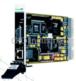


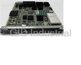
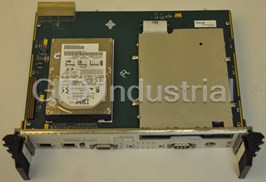
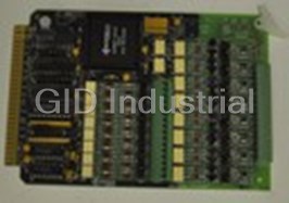


What they say about us
FANTASTIC RESOURCE
One of our top priorities is maintaining our business with precision, and we are constantly looking for affiliates that can help us achieve our goal. With the aid of GID Industrial, our obsolete product management has never been more efficient. They have been a great resource to our company, and have quickly become a go-to supplier on our list!
Bucher Emhart Glass
EXCELLENT SERVICE
With our strict fundamentals and high expectations, we were surprised when we came across GID Industrial and their competitive pricing. When we approached them with our issue, they were incredibly confident in being able to provide us with a seamless solution at the best price for us. GID Industrial quickly understood our needs and provided us with excellent service, as well as fully tested product to ensure what we received would be the right fit for our company.
Fuji
HARD TO FIND A BETTER PROVIDER
Our company provides services to aid in the manufacture of technological products, such as semiconductors and flat panel displays, and often searching for distributors of obsolete product we require can waste time and money. Finding GID Industrial proved to be a great asset to our company, with cost effective solutions and superior knowledge on all of their materials, it’d be hard to find a better provider of obsolete or hard to find products.
Applied Materials
CONSISTENTLY DELIVERS QUALITY SOLUTIONS
Over the years, the equipment used in our company becomes discontinued, but they’re still of great use to us and our customers. Once these products are no longer available through the manufacturer, finding a reliable, quick supplier is a necessity, and luckily for us, GID Industrial has provided the most trustworthy, quality solutions to our obsolete component needs.
Nidec Vamco
TERRIFIC RESOURCE
This company has been a terrific help to us (I work for Trican Well Service) in sourcing the Micron Ram Memory we needed for our Siemens computers. Great service! And great pricing! I know when the product is shipping and when it will arrive, all the way through the ordering process.
Trican Well Service
GO TO SOURCE
When I can't find an obsolete part, I first call GID and they'll come up with my parts every time. Great customer service and follow up as well. Scott emails me from time to time to touch base and see if we're having trouble finding something.....which is often with our 25 yr old equipment.
ConAgra Foods