

 Manufacturers
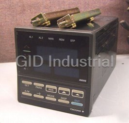
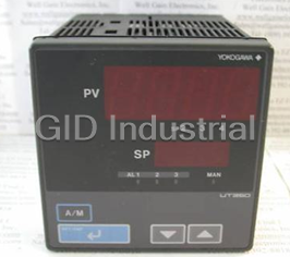
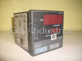
YOKOGAWA UT350L

Description
CONTROL
Part Number
UT350L
Price
Request Quote
Manufacturer
YOKOGAWA
Lead Time
Request Quote
Category
PRODUCTS - U
Datasheet

Extracted Text
Relay
Installation PositionCable Specifications and Recommended Cables Communication Function Power Supply Specifications
Communication protocol • Power supply: Rated voltage of 100 to 240 V AC (�10%), 50/60 Hz
Install the controller at an angle within 30° from horizontal
Front panel
Purpose Name and Manufacturer
• Personal computer link: Used for communication with a • Power consumption: Max. 20 VA (8.0 W max.)
with the front panel facing upward. Do not install it facing
Model UT350L
User’s of controller
Must not
2 personal computer, or UT link module of the FA-M3 • Internal fuse rating: 250V AC, 1.6A time-lug fuse
Power supply, grounding, relay contact outputs
600 V PVC insulated wires, JIS C 3307, 0.9 to 2.0 mm
downward. The position of right and left sides should be hori-
exceed 30�
controller (from Yokogawa Electric Corporation). • Data backup: Non-volatile memory (can be written to up to
Limit Controller User’s Manual
zontal. Thermocouple Shielded compensating lead wires, JIS C 1610, X- - -
Manual
• Ladder communication: Used for communication with a ladder 100,000 times)
(See Yokogawa Electric's GS 6B1U1-E.)
communication module of the FA-M3, or a programmable • Withstanding voltage
Rear of
RTD Shielded wires (three conductors), UL2482 (Hitachi Cable)
30� controller of other manufactures. - Between primary terminals* and secondary terminals**:
controllerCommunication Interface At least 1500 V AC for 1 minute
Installation
IM 05D01D21-01E Other signals Shielded wires
• Applicable standards: Complies with EIA RS-485 - Between primary terminals* and grounding terminal:
• Number of controllers that can be connected: Up to 31 At least 1500 V AC for 1 minute
Recommended Terminal Lugs
• Maximum communication distance: 1,200m - Between grounding terminal and secondary terminals**:
4th Edition: Apr. 1, 2005
• Communication method: Two-wire half-duplex, start-stop At least 1500 V AC for 1 minute
Applicable wire size Tightening torque
External Dimensions and Panel Cutout Dimensions
synchronization, non-procedural - Between secondary terminals**:
• Baud rate: 600, 1200, 2400, 4800, or 9600 bps At least 500 V AC for 1 minute
2
0.3 to 1.65 mm 0.8 N·m or less
* Primary terminals indicate power terminals and relay
UT350L Unit: mm
Display Specifications
output terminals
3.7mm� 3.7mm�
• PV display:
Large bracket ** Secondary terminals indicate analog I/O signal and
11 100
96
4-digit, 7-segment red LED display, character height of 20 mm
contact input terminals
This manual describes installation, wiring, and other tasks required to make the controller ready for operation.
• Setpoint display: 4-digit, 7-segment red LED display, character
• Insulation resistance: 20 M� or more at 500 V DC between
height of 9.3 mm
power terminals and grounding terminal
or
Contents • Status indicating lamps: LEDs
• Grounding: Class D grounding (grounding resistance of 100 �
or less)
Safety and EMC Standards
1. Safety Precautions
• Safety: Complies with IEC/EN61010-1 (CE), approved by Signal Isolations
2. Model and Suffix Codes
Terminal Covers (Optional parts) C22.2 No.61010-1, approved by UL508.
• PV input terminals: Isolated from other input/output terminals.
3. How to Install
Certified for FM-3810 and FM-3545.
Not isolated from the internal circuit.
4. How to Connect Wires Target Model Part Number Sales Unit
Installation category : CAT. II Pollution degree : 2 (IEC/
• 4-20 mA analog output terminals (for retransmission): Isolated
5. Hardware Specifications EN61010-1, C22.2 No.61010-1)
from other input/output terminals and internal circuit.
For UT350L T9115YD 1
Measurement category : I (CAT. I : IEC/EN61010-1)
6. Terminal Wiring Diagrams
• Relay contact control output terminals: Isolated between contact
Rated measurement input voltage : 10V DC max.(across
output terminals and from other input/output terminals and
terminals), 300V AC max.(across ground)
internal circuit.
Fold the cover in the direction
1. Before attaching the terminal cover, bend the side with
Rated transient overvoltage : 1500V (Note)
Small bracket
• Contact input terminals: Not isolated between contact input
of the arrow.
Introduction
the groove inward as shown in Fig. A. Be careful not to
Note : It is a value on the safety standard which is assumed
terminals and from communication terminals. Isolated from
1 to 10 mm (Panel thickness)
Figure A
Thank you for purchasing the UT350L limit controller.
bend it backwards. This not only marks it harder to by IEC/EN61010-1 in Measurement category I, and is not
other input/output terminals and internal circuit.
The controller is shipped from the factory with 3 hardcopy user’s manuals (A2 size). The 3 user’s manuals in hardcopy the value which guarantees an apparatus performance.
attach the cover but will also weaken its hold.
General installation Side-by-side close installation • Relay contact alarm output terminals: Not isolated between
format describe the operating procedures required for basic use. It is recommended that you refer to these user’s manuals to relay contact alarm outputs. Isolated from other input/
+0.8
117 min. [(N-1)�96+92] Fit the cover hold
0 CAUTION
understand [1] installation, [2] initial settings, [3] operating procedures, and [4] limit control function of the controller. 2. Fit the holes on the top and bottom (UT350L) of the output terminals and internal circuit.
over the protrusion
• RS-485 communication terminals: Not isolated from contact
on the mounting bracket.
terminal cover the projections on the brackets (Fig. B)
This equipment has Measurement category I, there- input terminals. Isolated from other input/output terminals
and lock in place. The figure right shows the attachment
and internal circuit.
fore do not use the equipment for measurementsHow to Use the Manuals of a terminal cover to UT350L.
• Power terminals: Isolated from other input/output terminals and
within Measurement categories II, III and IV.
internal circuit.
Purpose Manual Title Description Media
• Grounding terminals: Isolated from other input/output terminals
Setup Describes the tasks (installation, wiring, and others) required A2-size paper,
and internal circuit.
Installation Measurement category Description Remarks
(53)
145 min.
to make the controller ready for operations. front
"N" stands for the number of controllers to be CAT.1 For measurements performed
1
Figure B Environmental Conditions
on circuits not directly
Describes examples of setting PV input types, limit control type A2-size paper,
Basic operation installed.
5. Hardware Specifications connected to MAINS.
selection, and alarm types. • Normal operating conditions:
front
+0.8 However, the measured value applies if N � 5. CAT.2 For measurements performed Appliances, portable
Initial Settings 2
Retransmission Output
92
Making settings described herein allows you to carry out basic 0 on circuits directly connected equipments, etc. Ambient temperature: 0 to 50�C (40�C or less for side-by-side
PV Input Signals
Either PV, or target setpoint is output. to the low voltage installation.
control.
close installation)
CAT.3 For measurements performed
3 Distribution board,
• Number of inputs: 1 (terminals 11 - 12 - 13 ) • Number of outputs: 1 (terminals 16 - 17 )
The operating ambient temperature range is between 0�C.
in the building installation. circuit breaker, etc.
Operating
Describes key operation sequences. A2-size paper,
CAT.4 For measurements performed
+0.8 • Input type: Universal input system. The input type can be 4 Overhead wire, cable
• Output signal: 4-20 mA DC Temperature change rate: 10�C/h or less
procedures, 92 (25)
For operation control through external contact inputs, back
0 at the source of the low-voltage
systems, etc.
Operations
selected with the software. • Load resistance: 600 � or less
Ambient humidity: 20 to 90% RH (no condensation allowed)
troubleshooting, installation.
see User’s Manual. Installation
• Sampling period: 250 ms • Output accuracy: �0.3% of span under standard operating
Magnetic field: 400 A/m or less
and maintenance
• Burnout detection: Functions at TC, RTD, standard signal conditions (23 �2�C, 55 �10% RH, power frequency of
Continuous vibration at 5 to 14 Hz: Full amplitude of 1.2 mm or
Brief operation, Contains the parameter map used as a guideline for setting A2-size paper,
How to Install (0.4 to 2 V or 1 to 5 V) 50/60 Hz)
less
Internal Wiring
setpoint recording, parameters and lists of parameters for recording user settings. back and front
Parameters and 2
2
Upscale, downscale, and off can be specified.
3 T Continuous vibration at 14 to 150 Hz: 4.9 m/s or less
and Describes the limit control functions. Entrance4
Limit Control Output
1 2
For standard signal, burnout is determined to have occurred Cable
Short-period vibration: 14.7 m/s , 15 seconds or less
description of Functions
CAUTION Outlet
2
if it is 0.1 V or less. • Relay contact output (Standard type: terminals 1 - 2 - 3 )
Shock: 147 m/s or less, 11 ms
limit control function
• Input bias current: 0.05 �A (for TC or RTD b-terminal)
Installation height: Height above sea level of 2000 m or less
Number of outputs 1
• EMC standards: Complies with EN61326, EN61000-3-2,
Turn off the power to the controller before installing it on the panel because there is a possibility of electric shock. • Measurement current (RTD): About 0.13 mA
Warm-up time: 30 minutes or more after power on
EN61000-3-3 and EN55011 (CE).
• Input resistance: 1 M� or more for thermocouple or mV input
Output signal Three terminals (NC, NO, and common) Installation category based on IEC61010-1 : II (See Note)
Class A Group 1.
1. Safety Precautions About 1 M� for DC voltage input
Pollution degree based on IEC61010-1 : 2 (See Note)
Contact rating 250V AC or 30V DC, 3A (resistance load)
After opening the mounting hole on the
The instrument continues to operate at a measuring
• Allowable signal source resistance: 250 � or less for
Large bracket
The following symbol is indicated on the controller to ensure safe use.
panel, follow the procedures below to in- 10 ms
Resolution
accuracy of within �20% of the range during tests.
Panel (top mounting hardware) thermocouple or mV input
Note :
stall the controller:
Effects of signal source resistance: 0.1 �V/� or less
•The “Installation category” implies the regulation for
Construction, Installation, and Wiring
CAUTION
2 k� or less for DC voltage input
impulse withstand voltage. It is also called the
Contact Inputs
• Construction: Only the front panel is dust-proof and drip-proof
1. Insert the controller into the opening Effects of signal source resistance: About 0.01%/100 �
“Overvoltage category.” “II” applies to electrical
• Purpose: Confirmation of limit output.
(protection class IP55)
• Allowable wiring resistance: for RTD input
This symbol on the controller indicates that the operator must refer to an explanation in the user’s manual in order from the front of the panel so that the ter- equipment.
• Number of input: 1
For side-by-side close installation the controller loses its
Maximum 150 �/wire: Conductor resistance between three
• Input type: Non-voltage contact or transistor open collector input •“Pollution level” describes the degree to which a
to avoid the risk of injury or death of personnel or damage to the instrument. The manual describes how the operator minal board on the rear is at the far side.
dust-proof and drip-proof protection.
Terminal board
Direction to insert the wires should be equal
solid, liquid or gas which deteriorates dielectric
• Input contact rating: 12 V DC, 10 mA or more
should exercise special care to avoid electric shock or other dangers that may result in injury or loss of life.
• Material: ABS resin and polycarbonate
controller However, 10 �/wire for a maximum range of -150.0 to
• On/off determination: For non-voltage contact input, contact strength is adhering. “2” applies to a normal indoor
2. Set the brackets in place on the top and
• Case color: Black
Insert the controller 150.0�C. resistance of 1 k� or less is determined as “on” and contact
atmosphere.
• Weight: About 1 kg or less
bottom of the controller as shown in the
The following symbols are used in the hardcopy user’s manuals.
into the opening at Wire resistance effect: �0.1�C /10 �
resistance of 20 k� or more as “off.” • Transportation and storage conditions:
• Dimensions:
figure on the left, then tighten the screws
the front of the panel. For transistor open collector input, input voltage of 2 V or
• Allowable input voltage: �10 V DC for thermocouple, mV, or
Temperature: -25 to 70�C
96 (W) � 96 (H) � 100 (depth from panel face) mm
less is determined as “on” and leakage current must not
NOTE of the brackets. Take care not to over- RTD input
Temperature change rate: 20�C/h or less
• Installation: Panel-mounting type. With top and bottom
�20 V DC for DC voltage input exceed 100 �A when “off.”
tighten them. Humidity: 5 to 95% RH (no condensation allowed)
mounting hardware (1 each)
• Minimum status detection hold time: About 1 second.
• Noise rejection ratio: 40 dB (50/60 Hz) or more in normal mode
• Effects of changes in operating conditions
Indicates that operating the hardware or software in a particular manner may damage it or result in a system failure.
• Panel cutout dimensions:
• Devices connected to the UT350L must comply with IEC61010
120 dB (50/60 Hz) or more in common mode
- Effects from changes in ambient temperature:
+0.8 +0.8
Small bracket
92 (W) � 92 (H) mm
and 60950.
0 0
• Reference junction compensation error: �1.0�C (15 to 35�C)
- On voltage or thermocouple input, �1 �V/�C or �0.01%
(bottom mounting hardware)
• Installation position: Up to 30° upward facing
�1.5�C (0 to 15�C, 35 to 50�C)
of F.S./�C, whichever is larger
Contact Outputs
(not designed for facing downward)
IMPORTANT
• Applicable standards: JIS, IEC, DIN (ITS-90) for thermocouples
- On RTD input, �0.05�C /�C (ambient temperature) or less
• Purpose: Alarm output, FAIL output
• Wiring: M3.5 screw terminals (for signal wiring and power/
and RTD
- On analog output, �0.05% of F.S./�C or less
• Number of outputs: 2
ground wiring as well)
- Effects from power supply fluctuation (within rated voltage
Draws attention to information that is essential for understanding the operation and/or features of the controller.
• Relay contact rating: 240 V AC/1 A or 30 V DC/1 A (COM
4. How to Connect Wires
range)
terminal is common) ; 1a , FAIL output ; 1b
- On analog input, �1 �V/10 V or �0.01% of F.S./10 V,
• Devices connected to the UT350L must comply with IEC61010
CAUTION
equal to or less than whichever is larger
and 60950.
2. Model and Suffix Codes
- On analog output, �0.05% of F.S./ 10 V or less
6. Terminal Wiring Diagrams
Before using the controller, check that the model and suffix codes match your order.
1) Before carrying out wiring, turn off the power to the controller and check that the cables to be connected are not
NOTE
alive with a tester or the like because there is a possibility of electric shock.
Model Suffix Code Description
Do not use unassigned terminals as relay terminals.
2) For safety, be sure to install a circuit breaker switch (of 5A and 100V AC or 220V AC, and that conforms to
UT350L Limit controller
� Receiving 4-20 mA DC Current
Limit control output PV input
See Initial Settings User’s Manual ,
IEC60947) near the controller so as to be operated easily, and clearly indicate that the device is used to de-
Signals with the Controller
Type for more information.
-0
Standard type
Relay contact output RS-485 communication
* Wiring can only be carried out
energize the controller.
* When receiving 4-20 mA DC current signals,
TC input RTD input
0 None for controllers with
3) Wiring must be carried out by personnel who have basic electrical knowledge and practical experience.
set the PV input type to 1-5 V DC (setpoint “41”).
Optional functions NC
1
communication functions.
1 With communication
SDB(+)
23 11 A
Maximum baud rate: 9600 bps
NO +
2 12
12 +
Check that the following items are provided:
SDA(-)
24 12 b
NOTE
• Limit controller (of ordered model): .............................................................. 1
250 � 4-20mA
-
COM 3 13
• Brackets (mounting hardware): ...................................................................... 1 pair
RDB(+)
25 13
B 13 -
Contact rating: 250 V AC, 3 A
• Unit label: ....................................................................................................... 1
1) Provide power from a single-phase instrument power supply. If there is a lot of noise in the power line, insert an
30 V DC, 3 A (resistance load)
• User’s Manuals: .............................................................................................. 3 (A2 size)
RDA(-)
insulating transformer into the primary side of the line and use a line filter (recommended part: ZAC2205-00U 26 mV/V input
• User’s Manual (Model UT350L Communication Functions): ....................... 1 (A5 size)
Note: Connecting a 250 � resistor to the terminals is
from TDK) on the secondary side.
Supplied only for UT350L model with communication functions. optional.
SG
27
As a countermeasures against noise, do not place the primary and secondary power cables close to each other.
+ Model: X010-250-2 (resistor with M3.5 crimp-on terminal
12
2) For thermocouple input, use shielded compensating lead wires for wiring. For RTD input, use shielded wires lugs)
3. How to Install -
that have low conductor resistance and cause no significant differences in resistance between the three wires. 13
The cables to be used for wiring, terminal specifications, and recommended parts are as shown below.
1 21 11
NOTE 3) Control output relays may be replaced. However, because they have a life of 100,000 times that of the resis-
2 12
tance load, use auxiliary relays to turn on/off a load.
Alarm output
4) The use of inductance (L) loads such as auxiliary relays, motors and solenoid valves causes malfunction or
3 23 13
To install the controller, select a location where:
UT
Alarm-1 output
relay failure; always insert a CR filter for use with alternating current or a diode for use with direct current, as
(1) no one may accidentally touch the terminals,
6
AL1
4 24 14
a spark-removal surge suppression circuit, into the line in parallel with the load.
(2) mechanical vibrations are minimal,
5 25 15
5) When there is the possibility of being struck by external lightning surge, use the arrester to protect the instru- Alarm-2 output 5
Retransmission output * PV retransmission is configured at factory
(3) corrosive gas is minimal,
150mm AL2
ment.
before shipment.
(4) temperature can be maintained at about 23°C and the fluctuation is minimal,
6 26 16
7
Common COM
(5) no direct radiant heat is present,
16 +
7 27 17
4-20 mA DC
(6) no magnetic disturbances are caused,
Relay contact rating: 240 V AC, 1 A
150mm 150mm
For DC Relay WiringFor AC Relay Wiring
-
30 V DC, 1 A (resistance load) 17
(7) no wind blows against the terminal board (reference junction compensation 8 18
150mm
element),
Load resistance: 600 � or less
UT350L External AC power supply
9 19
(8) no water is splashed,
UT350L
External DC power supply
10 30 20
(9) no flammable materials are around,
R
Never place the controller directly on flammable items or equipment.
R
If the controller has to be installed close to flammable items or equipment, be sure to provide shielding panels all
Power supply
Confirmation of limit status
around the controller, at least 150mm away from every side; the panels should be made of either 1.43mm-thick Diode CAUTION
Power supply
UT’s contact
Relay
(Mount it directly Before carrying out wiring, turn off the power to External contact input
metal-plated steel plates or 1.6mm-thick uncoated steel plates.
CR filter
UT’s contact
Relay L
(Use one with a relay coil the controller and check that cables to be connected
to the relay coil
Contact
(Mount it directly 8 +5V Transistor contact
are not alive with a tester or the like because UT
(Use one with a relay coil rating
rating less than the UT’s
terminal (socket).)
to the relay coil DI
there is a possibility of electric shock.
less than the UT’s contact rating.) DI
contact rating.) N 19
19
RESET when DI=ON
9
terminal (socket).)
NOTE
(However, setup parameter
DIS=DI)
10
COM
Never touch the opening at the bottom of the case. It is to be used in the factory at shipping.
Allowable range: 100 to 240 V AC (�10%) 20 20
COM
Common
(free voltage)
50/60 Hz shared
Contact rating: 12 V DC, 10 mA or more
IM 05D01D21-01E (1)
Insert a screwdriver into the
brackets to tighten the screws.
96
+0.8
92
0
91.8
112
7 mm or less
7 mm or less
IM 05D01D21-01E (2)
The following operating procedure describes an example of setting the PV input terminal
Instrument Input Range Codes
4. Changing Alarm Type
12 13
controller to a K-type thermocouple (-199.9°F to 999.9°F) and the Thermocouple/mV/V input.............................. -
The following operating procedure describes an example of chang-
Select the unit from the UNIT parameter.
Alarm output terminals Factory-set defaults
11 12 13
measurement range of 0.0°F to 200.0°F. RTD input .................................................. - -
Model UT350L
User’s
ing alarm-1 (factory-set default:PV high limit alarm) to PV low limit
6 7
Alarm-1 (terminal numbers ).......PV input high limit alarm -
Instrument Input Instrument
SET/ENT
Input Type Measurement Accuracy
alarm. Alarm-2 (terminal numbers ).......PV input low limit alarm 5 - 7
Bring the operating display into view (display Press the key once to display the parameter
Range Code Input Range
Limit Controller User’s Manual 1. 10.
Manual
appears at power on). “UNIT” (PV input unit).
When you have changed alarm type, the alarm setpoint will be ini-
-200 to 1370�C
1
-300 to 2500�F tialized; set the alarm setpoint again.
Displays
-199.9 to 999.9�C
Displays K 2 SET/ENT
Bring the operating display into view (appears at Press the key once to display the
Initial Settings parameter 0 to 2300�F
6.
IM 05D01D21-02E 1.
PV.
“UNIT”. �0.1% of instrument range �1 digit for temperatures power-on). parameter “AL1” (alarm-1 type).
-199.9 to 500.0�C
3
equal to or higher than 0�C
-199.9 to 999.9�F
�0.2% of instrument range �1 digit for temperatures Displays
-199.9 to 999.9�C
4th Edition: Apr. 1, 2005 Displays target
Displays
J4
below 0�C parameter
-300 to 2300�F
setpoint.
PV.
-199.9 to 400.0�C “AL1”.
5
-300 to 750�F
T
SET/ENT SET/ENT
0.0 to 400.0�C Displays target
Press the key for more than 3 seconds to Press the key once to display the parameter
This manual describes examples of setting PV input types, limit control types, and alarm types. 2. 11. 6
-199.9 to 750.0�F setpoint.
call up the menu “OP.PA”. “RH” (maximum value of PV input range).
Carrying out settings described herein allows you to perform basic control.
�0.15% of instrument range �1 digit for temperatures
Refer to examples of various settings to understand how to set parameters required. Refer to “1. Basic Key Operation
Displays 0 to 1800�C equal to or higher than 400�C
Displays
B7
parameter 32 to 3300�F �5% of instrument range �1 digit for temperatures SET/ENT
Sequence and Parameter Map” in Parameters and Functions User’s Manual for an easy to understand explanation
menu “OP.PA”.
Press the key for more than 3 seconds to Press the or key to display the required
2. 7.
below 400�C
SET/ENT “RH”.
call up the menu “OP.PA”. setpoint. The figure below shows an example of
of setting various parameters. If you cannot remember how to carry out an operation during setting, press the key for
0 to 1700�C
S8 setting PV low limit alarm.
more than 3 seconds. This brings you to the display (operating display) that appears at power-on.
32 to 3100�F
�0.15% of instrument range �1 digit
0 to 1700�C
R9
32 to 3100�F Displays menu
Thermocouple
�0.1% of instrument range �1 digit “OP.PA”.
Contents
-200 to 1300�C
N10 �0.25% of instrument range �1 digit for temperatures
Press the key once to display the menu
Press the or key to display the required -300 to 2400�F
3. 12.
below 0�C
1. Names and Functions of Front Panel Parts “STUP”.
setpoint. The figure below shows an example of
Blinks during
-199.9 to 999.9�C
E11
2. Setting PV Input Type setting the maximum value of PV input range to
change.
-300 to 1800�F
200.0°F.
3. Changing Limit Control Type
-199.9 to 900.0�C �0.1% of instrument range �1 digit for temperatures
L(DIN) 12
4. Changing Alarm Type -300 to 1300�F equal to or higher than 0�C
Displays menu
SET/ENT
Press the key once to register the setpoint.
Press the key once to display the menu
-199.9 to 400.0�C �0.2% of instrument range �1 digit for temperatures 8.
3.
“STUP”.
13
“STUP”.
-300 to 750�F below 0�C
U(DIN)
You can take the same
0.0 to 400.0�C
14 Display menu
Blinks during
1. Names and Functions of Front Panel Parts
steps for alarm-2 type
-199.9 to 750.0�F
“STUP”.
change.
0 to 2300�C (AL2) that are displayed
W15 �0.2% of instrument range �1 digit
32 to 4200�F after this.
1. Measured value (PV) display
0 to 1390�C
Platinel 2 16 �0.1% of instrument range �1 digit
SET/ENT SET/ENT
Press the key once to display the parameter Press the key once to register the setpoint. 32 to 2500�F
13.
4.
�0.5% of instrument range �1 digit for temperatures
“PWD”.
0 to 1900�C
2. Setpoint display
PR20-40 17 equal to or higher than 800�C
3. EXCEEDED lamp
32 to 3400�F
SET/ENT SET/ENT
No guarantee of accuracy for temperatures below 800�C
Press the key once to display the Press the key for more than 3 seconds.
9.
4.
W97Re3-
0 to 2000�C parameter “PWD”. This returns you to the display shown at power-on
18 �0.2% of instrument range �1 digit
5. Alarm indicator lamps
W75Re25 32 to 3600�F
4. Output indicator lamp (figure below).
-199.9 to 500.0�C
30 �0.1% of instrument range �1 digit (Note1) (Note2)
8. and keys -199.9 to 999.9�F
Displays
6. RESET key JPt100
-150.0 to 150.0�C
PV.
31 �0.2% of instrument range �1 digit (Note1)
7. SET/ENT key -199.9 to 300.0�F
SET/ENT SET/ENT -199.9 to 850.0�C
RTD 35
Press the key once to display the menu Press the key once to display the parameter
5. 14.
-300 to 1180�F Displays target
“FUNC”. �0.1% of instrument range �1 digit (Note1) (Note2)
“RL” (minimum value of PV input range).
-199.9 to 500.0�C setpoint.
Pt100 36
Name of Part Function
-199.9 to 999.9�F
Displays
Displays PV.
Displays -150.0 to 150.0�C
Measured value (PV) 37 �0.2% of instrument range �1 digit (Note1)
parameter
Displays a parameter symbol when you set a parameter. SET/ENT
1. menu “FUNC”. -199.9 to 300.0�F
Press the key once to display the menu When setting an alarm setpoint, see “3. Setting
display “RL”. 5. 10.
Displays an error code (in red) if an error occurs. Standard 0.4 to 2 V 40 0.400 to 2.000 V
“FUNC”. Alarm Setpoints” in Operations User’s Manual .
signal 1 to 5 V 41 1.000 to 5.000 V
Displays the setpoint (SP) during operation.
�0.1% of instrument range �1 digit
2. Setpoint display
0 to 2 V 50 0.000 to 2.000 V Displays menu
Displays the set value of parameters on the parameter setting display.
The read-out range can be scaled between -1999 and
0 to 10 V 51 0.00 to 10.00 V “FUNC”.
DC voltage 9999.
Light (green) to indicate the exceeded status of PV.
-10 to 20 mV 55 -10.00 to 20.00 mV
EXCEEDED lamp
3.
Lights while PV exceeds SP.
0 to 100 mV 56 0.0 to 100.0 mV
Press the key once to display the menu “I/O”.
Press the or key to display the required
Light (green) to indicate the output status.
6. 15. * Performance in the standard operationg condition (at 23�2�C, 55�10%RH, and 50/60Hz power frequency)
4. Output indicator lamp
setpoint. The figure below shows an example of
Lights while the relay output is OFF. Note1: The accuracy is �0.3�C of instrument range �1 digit for a temperature range from 0�C to 100�C.
setting the minimum value of PV input range to
Note2: The accuracy is �0.5�C of instrument range �1 digit for a temperature range from -100�C to 200�C.
5. Alarm indicator lamps If any of alarms 1 and 2 occurs, the respective alarm indicator lamp (AL1 and AL2) is lit (in orange).
0.0°F.
* To receive a 4-20 mA DC signal, select a standard signal of 1 to 5 V DC and connect it to a 250� resistor. This resistor is optional.
Displays Model: X010-250-2 (resistor with M3.5 crimp-on terminal lugs)
6. RESET key Used to confirm and reset the limit output and related parameters. menu “I/O”.
List of Alarm Types
3. Changing Limit Control Type
SET/ENT Used to switch or register a parameter. Pressing the key for more than 3 seconds allows you to switch
7. Blinks during
key between the operating display and the menu for operating parameter setting display alternately. The table below shows the alarm types and alarm actions.
The following operating procedure describes an example of changing limit control type (factory-set default: high limit type)
change.
In the table, codes 1 to 10 are not provided with stand-by actions, while codes 11 to 20 are provided with stand-by actions.
Used to change numerical values. On setting displays for various parameters, you can change to low limit type.
and
target setpoints and parameters. Pressing the key decreases a numerical value,
8.
SET/ENT Alarm type code Alarm type code
keys Bring the operating display into view (display Press the key several times to display the
while pressing the key causes it to increase. You can hold down a key to gradually increase
1. 6. Alarm action Alarm action
SET/ENT SET/ENT
Press the key once to display the parameter Press the key once to register the setpoint.
7. 16. appears at power on). parameter “HI.LO” (limit control type selection). Contact Contact Contact Contact
the speed of change.
Alarm type Alarm type
closes opens closes opens
“IN” (PV input type).
“Open/close” shows status of relay contact, “Open/close” shows status of relay contact,
if alarm if alarm if alarm if alarm
and “lit” and “unlit” shows status of lamp and “lit” and “unlit” shows status of lamp
Displays
occurs occurs occurs occurs
Displays
Displays
parameter
No alarm OFF
Hysteresis
IMPORTANT PV.
parameter “IN”.
“HI.LO”.
Hysteresis
6
De-energized
Open (lit) Closed
1
on deviation low
(unlit)
The controller automatically returns to the display at the time of power-on (i.e., operating display) if no key is
Displays target
PV high limit Open (unlit) Closed (lit) limit alarm
Deviation
16
PV
setpoint
operated for at least one minute. setpoint.
11
PV Alarm setpoint Target SP
Hysteresis Hysteresis
Hysteresis
SET/ENT
SET/ENT
2 Closed Open Closed 7
Press the key for more than 3 seconds to
Press the key for more than 3 seconds. Press the or key to display the required
Press the or key to display the required 2. 7.
17.Setting of Main Parameters at the Factory before Shipment 8. Deviation high (lit) (unlit) (lit)
call up the menu “OP.PA”. PV low limit Closed (lit) Open (unlit)
setpoint. The figure below is an example of the
setpoint. The figure below is an example of the This returns you to the display shown at power-on and low limits
Deviation setpoint PV
12 17
(figure below). controller set to a low limit type.
controller set to a Pt100 resistance temperature
Alarm setpoint PV
Item Factory-set defaults
Target SP
detector (-199.9°F to 999.9°F). Displays
PV input type Thermocouple type K (-300 to 2500�F) (1)
menu “OP.PA”. Hysteresis
Hysteresis
Hysteresis
Closed
Displays
Hight limit (HI)
Limit control type (lit)
3 Open Open 8
PV. Deviation within
Time unit for duration time
Hour and minute (0) Blinks during Deviation high (unlit) (unlit)
Open (unlit) Closed (lit)
high and low
limit
Alarm output Alarm-1: PV high limit (1), Alarm-2: PV low limit (2) change.
Blinks during limits
PV
Deviation setpoint
Deviation setpoint 13 18
PV
Retransmission output PV retransmission (1) Displays target
change.
Target SP
Target SP
setpoint.
Hysteresis
Hysteresis
2. Setting PV Input Type
4 9
Closed (lit) Open (unlit)
SET/ENT Deviation low De-energized
SET/ENT Closed
Press the key once to register the setpoint.
Open (lit)
Press the key once to register the setpoint. * If the type of input is voltage, also configure Press the key once to display the menu 8.
limit on PV high limit (unlit)
9. 3.
Deviation setpoint
NOTE
the PV Input Decimal Point Position (SDP), “STUP”. 14 19
PV
PV Alarm setpoint
Target SP
Maximum Value of PV Input Scale (SH) and
Minimum Value of PV Input Scale (SL) that are
Hysteresis
The controller is configured to the initial value of each parameter at the factory before shipment. Displays menu
Hysteresis
displayed after parameter RL.
“STUP”. 5 10
First check the initial values shown in “2. Lists of Parameters,” in Parameters and Functions User’s Manual and De-energized on
Closed Open (lit) De-energized
Closed
deviation high
Open (lit)
(unlit)
change parameter values as necessary.
on PV low limit (unlit)
limit alarm Deviation
15 20
PV
setpoint
Alarm setpoint PV
Target SP
Example of Temperature Input Example of Voltage Input
The controller stops when in a FAIL state.
Fault diagnosis
FAIL output
The control output is set to “OFF”,
Fault diagnosis output 22
1V 2V 4V 5V (input signal) 21
-300°F 2500°F
output (Note 1) (Note 2)
alarm output is set to “OFF” and
Instrument SET/ENT
SET/ENT
Instrument NOTE retransmission output is set to 0%.
Press the key once to display the parameter
Press the key for more than 3 seconds.
input range 4. 9.
input range
“PWD”. This returns you to the display shown at power on
(figure below).
Set a range
RH The controller may automatically initialize the registered operating parameter setpoints if any change is made to the
RL PV input range
Stand-by Action
PV input range to be
data item PV Input Type (IN), Maximum Value of PV Input Range (RH), Minimum Value of PV Input Range (RL), Displays
Set a range to
controlled
0°F 800°F
be controlled
PV Input Decimal Point Position (SDP), Maximum Value of PV Input Scale (SH) or Minimum Value of PV Input PV.
PV input scale
Minimum value of Maximum value of
�C
3 3 Scale (SL). After a change has been made to any of these data items, be sure to verify the registered operating
Normal Abnormal
PV input range (RL) PV input range (RH)
0.0m /h 50.0m /h
Treated
parameter setpoints to ensure that they are correct. If any data item has been changed to its default, set it to a
Minimum value of Maximum value of Displays target
The alarm
as normal
PV input scale (SL) PV input scale (SH)
required value. setpoint.
output turns on.
Low limit of
Parameters to be set for temperature input Parameters to be set for voltage input
1. PV input type (IN): Set according to a sensor 1. PV input type (IN): Set according to an input signal alarm setpoint
2. Maximum value of PV input range (RH): Set the 2. Maximum value of PV input range (RH): Set the maximum value of an input signal.
SET/ENT
Press the key once to display the menu
maximum value of the range to be controlled. 3. Minimum value of PV input range (RL): Set the minimum value of an input signal.
5.
The alarm output does not
3. Minimum value of PV input range (RL): Set the 4. Position of PV input decimal point (SDP): Set the position of the decimal point for PV input display. “FUNC”.
turn on in this region even
minimum value of the range to be controlled. 5. Maximum value of PV input scale (SH): Set the maximum value of the scale to be controlled.
if the PV value is below the
6. Minimum value of PV input scale (SL): Set the minimum value of the scale to be controlled.
Displays low limit of the alarm setpoint.
menu “FUNC”.
Time
Power-on
Note 1: The fault diagnosis output turns on in case of input
burnout, A/D converter failure, or reference junc-
tion compensation (RJC) failure. In case of RJC
failure, the controller continues control under the
condition of “RJC=OFF”.
Note 2: The FAIL output is on during normal operation and
turn off in case of ROM failure, RAM failure, power
failure.
IM 05D01D21-02E (1)
When limit control type is
set as low limit.
3. Setting Alarm SetpointsErrors at Power On
5. Operation in Confirmation Display
The following operating procedure describes an example of setting Following parameters can be seen in the confirmation display. These parameters can be confirmed and reset by pressing the
The following table shows errors that may be detected by the fault diagnosis function when the power is turned on.
Alarm output terminals Factory-set defaults
Model UT350L
User’s
160.0 to alarm-1 setpoint. Check alarm type before setting the alarm
key at each parameter display.
6 7
Alarm-1 (terminal numbers )............PV high limit alarm -
Error indication
Description Control Alarm Retransmission Communi-
setpoint. To change the type of alarm, see “4. Changing Alarm Type”
Alarm-2 (terminal numbers )............PV low limit alarm 5 - 7
PV Remedy
Limit Controller User’s Manual
Duration time (TIME)
Manual (on PV display unit) of error output output output cation
in Initial Settings User’s Manual .
(E000) Faulty RAM
Maximum value of PV (HI) or Minimum value of PV (LO)
None 0% or less Stopped
0% or less
Bring the operating display into view (display Press the or key to display the required
4.
1. (E001) Faulty ROM OFF
Operations
IM 05D01D21-02E appears at power on). setpoint. or OFF
Faulty
Bring the operating display (PV/SP dispaly) into When the instrument is specified as high limit type, (E002)
System data error 0% 0%
1. Contact us
Displays PV.
view (display appears at power on). go to the step 4.
for repair.
PV decimal point blinks. Normal action Normal action Normal action Normal action
4th Edition: Apr. 1, 2005 When the instrument is specified as low limit type, go
Faulty calibration
Normal
(out of (out of (out of (out of
to the step 5.
value
Displays accuracy) accuracy) accuracy) accuracy) action
Blinks during
target setpoint.
Frequently asked questions
What makes Elite.Parts unique?

What kind of warranty will the UT350L have?
Which carriers does Elite.Parts work with?
Will Elite.Parts sell to me even though I live outside the USA?
I have a preferred payment method. Will Elite.Parts accept it?


What they say about us
FANTASTIC RESOURCE
One of our top priorities is maintaining our business with precision, and we are constantly looking for affiliates that can help us achieve our goal. With the aid of GID Industrial, our obsolete product management has never been more efficient. They have been a great resource to our company, and have quickly become a go-to supplier on our list!
Bucher Emhart Glass
EXCELLENT SERVICE
With our strict fundamentals and high expectations, we were surprised when we came across GID Industrial and their competitive pricing. When we approached them with our issue, they were incredibly confident in being able to provide us with a seamless solution at the best price for us. GID Industrial quickly understood our needs and provided us with excellent service, as well as fully tested product to ensure what we received would be the right fit for our company.
Fuji
HARD TO FIND A BETTER PROVIDER
Our company provides services to aid in the manufacture of technological products, such as semiconductors and flat panel displays, and often searching for distributors of obsolete product we require can waste time and money. Finding GID Industrial proved to be a great asset to our company, with cost effective solutions and superior knowledge on all of their materials, it’d be hard to find a better provider of obsolete or hard to find products.
Applied Materials
CONSISTENTLY DELIVERS QUALITY SOLUTIONS
Over the years, the equipment used in our company becomes discontinued, but they’re still of great use to us and our customers. Once these products are no longer available through the manufacturer, finding a reliable, quick supplier is a necessity, and luckily for us, GID Industrial has provided the most trustworthy, quality solutions to our obsolete component needs.
Nidec Vamco
TERRIFIC RESOURCE
This company has been a terrific help to us (I work for Trican Well Service) in sourcing the Micron Ram Memory we needed for our Siemens computers. Great service! And great pricing! I know when the product is shipping and when it will arrive, all the way through the ordering process.
Trican Well Service
GO TO SOURCE
When I can't find an obsolete part, I first call GID and they'll come up with my parts every time. Great customer service and follow up as well. Scott emails me from time to time to touch base and see if we're having trouble finding something.....which is often with our 25 yr old equipment.
ConAgra Foods