

 Manufacturers
YOKOGAWA RAMC
Description
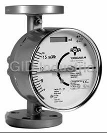
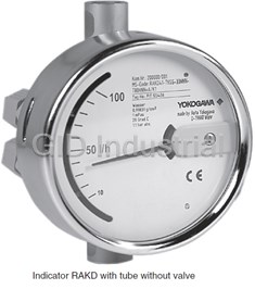
Yokogawa RAMC Metal Short-stroke Rotameter
Part Number
RAMC
Price
Request Quote
Manufacturer
YOKOGAWA
Lead Time
Request Quote
Category
PRODUCTS - R
Datasheet

Extracted Text
Model RAMC General Metal Short-stroke Rotameter Specifications GS 01R01B02-00E-E A float is guided concentrically to a special shaped conic metal tube. The position of this float is magnetically transmitted to the indicator. The short-tube Rotameter is used for measurement of flow rates of liquids and gases. Its special application is in troubled, opaque or aggressive mediums. The instrument is mounted in a vertical pipeline with flow direction upwards. The indicators are exchangeable without influence on the accuracy. FEATURES - Different process connections like flanges according EN and ASME - All wetted parts in stainless steel or PTFE - Maximum flow 0.025 - 130 m³/h water resp. 0.75 - 1400 m³/h air (20 °C / 1.013 bar abs) - Measuring accuracy acc. Directive VDI/VDE 3513 sheet 2 (q =50%) G - Float damping to avoid float bouncing with gas applications - Optional heat tracing (with steam or fluid heat carrier) - Indicator in stainless steel, aluminium, protection class IP66/67 - Local indicator without additional power supply - Microprocessor controlled transmitter with 24 V, 115 V or 230 V power supply RAMC with housing type 90 - Intrinsically safe version (Ex-i): ATEX, FM, CSA, SAA, NEPSI, CCOE - Flame proof version (Ex-d): ATEX, NEPSI, CCOE) - Dust explosion proof: ATEX, NEPSI, CCOE - Suitable for SIL application, FMEDA report available - Limit switches, also available as “Fail Safe” version Electronic transmitter as standard with local-controlling display with the following features : - Flow indication (totalize, actual, percent) - Indication of different volume- and mass flow units - Second (manual) calibration storing - Patented float blocking indication function - Signal output damping - Error message indication - Temperature measurement in the electronic transmitter - HART- communication - Profibus PA- communication Contents Features page 1 Standard Specifications page 2 Compliance with IEC 61508 page 4 Compliance with ISO 13849 page 4 Hazardous Area Specifications page 5 Installation page 8 Model Specifications page 11 RAMC with housing type 91 Options page 11 Process connection table for metal tubes page 13 Flow tables metal tubes page 14 Process connection and flow table for tubes page 15 with PTFE lining Temperature graphs page 16 Dimensions and weights page 17 GS 01R01B02-00E-E Rota Yokogawa GmbH & Co. KG Rheinstr. 8 © Copyright October 2004 (Rü) D-79664 Wehr 21st edition, July 2011 (Rü) Germany 2 Installation : STANDARD SPECIFICATIONS - Mounting direction : vertical - Flow direction : upwards MEASURING TUBE - Mounting length : see tables 10, 12, 13, 14 Materials of wetted parts : - Straight pipe inlet length - Stainless steel AISI 316L (1.4404) : DN 80/100 at least 5D, not - PTFE necessary for smaller sizes - Other materials on request Weight : Fluids to be measured : See table 15 suitable for a variety of liquids, gas and steam Measuring range : See table 11 and 12 Measuring range ratio : LOCAL INDICATOR 10:1 (Indicator/Transmitter Code -T) Process connections / Stainless steel : Principle : - Flanges : - acc. EN1092-1 The indication is made by magnetic coupling of a magnet DN100 – DN150 PN16 enclosed in the float and a magnet in the indication unit, DN15 – DN100 PN40 which follows the movements of the float, with a pointer. DN50 – DN80 PN63 Indicator housing : DN15 – DN50 PN100 - Materials : - Stainless steel (1.4301 / 304) - acc. ASME B 16.5 (housing type 90) ½” – 6“ Class 150 raised face - painted aluminium casting ½” – 6“ Class 300 raised face (housing type 91) ½” – 3“ Class 600 raised face each with safety-glass window Roughness of sealing - Degree of protection : Form B1 : RA 3.2 - 6.3 - IP66/67 Form B2 : RA 0.8 - 3.2 Scales : ASME : RA 3.2 - 6.3 - Standard : removable aluminium plate with scale -Threaded connection : (double scale as option) - male acc. DIN 11851 - Marking : direct readable units or percentage of Qmax. - NPT- female Transportation- and Storage condition : - G- female -40°C to +110°C - Clamp acc. DN25 / 1“ – DN100 / 4“ Process pressure : Depends on process connection, see table 10 to 12 higher pressure (up to 700 bar) on request Process temperature : - medium wetted parts made of stainless steel : -200 …+370 °C - medium wetted parts made of PTFE : -80 … +130 °C See fig. 7a to 7c Measuring accuracy : Table 1 Material of Size Measuring accuracy wetted parts acc. Directive VDI/ VDE 3513 sheet 2 (q =50%) G SS DN 15 - 100 1.6% SS DN 125 - 150 2.5% PTFE DN 15 -100 2.5% Heat tracing Pressure Equipment Directive (PED) Directive 97/23/EG : Tubes : - Modul : H - Fluid Group : 1 (dangerous fluids) - Produced acc. to category : III - Classification : Table 6 (piping) Heating (options /T1 to /T6) : - Art. 3 section 3 : (Volume < 1L) - Fluid Group : 2 (non-dangerous fluids) - Classification : Table 2 (vessels) CANADIAN REGISTRATION NUMBERS (CRN ) available upon request All Rights Reserved. Copyright © 2004, Rota Yokogawa GS 01R01B02-00E-E 21st edition, July 20, 2011-00 3 ELECTRONIC TRANSMITTER Electromagnetic compatibility (EMC) : (Indicator/Transmitter Code -E, -H, -G) - Acc. EN 61326-1: 2006, Class A, Table 2 and Standard type (Code -E) : EN 61326-2-3 : 2006 : Power supply : Criterion A, restriction: HF- immunity between 500 MHz - 4- wire units with galvanic isolation : and 750 MHz : criterion B - 230 V AC +10 %/-15 %, 50/60 Hz, RAMC with Profibus PA : fuse 0.063 A, time lag, (5x20) mm Criterion A: Burst, Surge, HF- Immunity - 115 V AC +10%/-15 %, 50/60 Hz, Criterion B: ESD fuse 0.125 A, time lag, (5x20) mm In case of single sided grounding of the cable shield it - 2/3- wire units : - U = 13.5 V... 30 V DC is possible that for all tests criterion B is reached. Output signal : Unit safety acc. DIN EN 61010-1: 2001 : - 4- wire units : - 0 - 20 mA, 4 – 20 mA - Over voltage category : II (acc. VDE 0110 or IEC 664) - pulse output (option /CP) - Pollution degree : I max. frequency 4 Hz see fig. 3 - Safety class : I (with 115 / 230V AC power supply) - 3- wire units : 0 - 20 mA, 4 - 20 mA III (with 24V DC power supply and - 2- wire units : 4 - 20 mA Fieldbus type) The 20 mA point is selectable between 60% and 100% of Qnom. Load resistance : POWER SUPPLY FOR ELECTRONIC TRANSMITTER - 4- wire units : ≤ 500 Ω (Option /UT) - 2/3- wire unit : ≤ (U-13.5 V)/20 mA Type : HART- communication type (Code -H) : Power supply with galvanically separated input and output Power supply : - RN221N-B1, HART- compatible - 2-wire units : U = 13.5 V... 30 V DC Supply voltage : Output signal : 20 ... 250 V DC / AC 50/60 Hz - 2- wire units : 4 – 20 mA Maximum load : Load resistance : 700 Ω - HART-version : 250 … 500 Ω Output signal : Profibus PA - communication type (Code -G) : - 2- wire bus connection not polarity sensitive : 9 ... 32 V DC 4 - 20 mA acc. to IEC 61568-2 and FISCO model - Basic current : 14 mA - Failure current (FDE) : 10mA additional to basic current CABLE GLAND (for transmitter –E, -H and –G) : - Transmission rate : 31.25 kBaud Size : - AI block for volume flow or mass flow - M16x1.5 (standard) - Configurable with PDM DD - Thread M20x1.5 (option /A13; standard for option /KF1) - Supports I&M- functions - Thread ½” NPT (option /A5) Digital display : Cable diameter : 8- digits 7- segment-LC-display character height 6 mm 6 – 9 mm Process-/ Ambient temperature : Maximum cross section of core : The dependency of the process temperature from the Ø 1.5 mm² ambient temperature is shown in fig. 7a to fig. 7c. The internal temperature of the electronic transmitter can be indicated on the display or checked via HART LIMIT SWITCHES IN STANDARD VERSION communication. (option /K1 to /K3) Measurement of the internal transmitter temperature : Type : - Range : -25 °C to +70 °C Inductive proximity switch SC3.5-N0 acc. DIN EN 60947-5-6 - Accuracy : ± 5 °C Nominal voltage : Transportation- and Storage condition : 8 V DC -40 °C to +70 °C Output signal : 1) Linearity : ≤ 1 mA or ≥ 3 mA ± 0.2 % f.s. 1) Hysteresis : ± 0.1 % f.s. 1) LIMIT SWITCHES IN FAIL SAFE VERSION Repeatability : (option /K6 to /K10) ± 0.1 % f.s. 1) Type : Influence of power supply : Inductive proximity switch SJ3.5-SN; SJ3.5-S1N ± 0.1 % f.s. 1) acc. DIN EN 60947-5-6 (NAMUR) Temperature coefficient of the output signal : Nominal voltage : ± 0.5 % /10 K f.s. 1) 8 V DC AC-part of output signal : Output signal : ± 0.15 % f.s. 1) Long-time stability : ≤ 1 mA or ≥ 3 mA ± 0.2 % /year Max. output signal : 21.5 mA HYSTERESIS OF LIMIT SWITCHES Output signal in case of failure : Min-contact / Max-contact : ≤ 3.6 mA (acc. NE 43) - pointer movement ≈ 0.8 mm Response time (99%) : - float movement ≈ 0.8 mm About 1.5 s (damping 1s) Minimum distance between 2 contacts : ≈ 2 mm 1) referenced to 20°C ambient temperature All Rights Reserved. Copyright © 2004, Rota Yokogawa GS 01R01B02-00E-E 21st edition, July 20 , 2011-00 4 Table 4 Limit switch as Min-Min-contact in fail-safe version CABLE GLAND (option /K1 to /K10) Size : Option /K9 - M16x1.5 (standard) Signal - Thread M20x1.5 (option /A13; standard for option /KF1) Function Pointer - Thread ½” NPT (option /A5) SJ3,5-S1N Cable diameter : above LV 3 mA 6 – 9 mm MIN below LV 1 mA Maximum cross section of core : Fail Safe 1 mA Ø 1.5 mm² Signal Function Pointer SJ3,5-SN above LV 3 mA POWER SUPPLY FOR LIMIT SWITCHES (Option /W__) MIN below LV 1 mA Type : Fail Safe 1 mA acc. DIN EN 50227 (NAMUR) Note: LV = Limit value - KFA5-SR2-Ex*-W (115 V AC), * = 1 or 2 - KFA6-SR2-Ex*-W (230 V AC), * = 1 or 2 Table 5 Limit switch as Max-Max-contact in fail-safe version - KFD2-SR2-Ex*-W (24 V DC), * = 1 or 2 - KHA6-SH-Ex1 (115/230 V AC), Fail Safe, 1 channel Option /K10 - KFD2-SH-Ex1 (24 V DC), Fail Safe, 1 channel Signal Power supply : Function Pointer SJ3,5-SN - 230 V AC ± 10%, 45-65Hz - 115 V AC ± 10%, 45-65Hz above LV 1 mA - 24 V DC ± 25% MAX below LV 3 mA Fail Safe 1 mA Relay output : 1 or 2 potential-free changeover contact(s) Switching capacity : Signal Function Pointer max. 250 V AC, max. 2 A SJ3,5-S1N above LV 1 mA Note : MAX below LV 3 mA If Fail-Safe limit switch option /K6 or /K7 is ordered, for power Fail Safe 1 mA supply option /W2E or /W4E must be selected. Note: LV = Limit value If Fail-Safe limit switch option /K8, /K9 or /K10 is ordered, for power supply option /W2F or /W4F must be selected. SWITCHING LEVELS FOR LIMIT SWITCHES COMPLIANCE WITH IEC 61508 Table 2 Min, Max and Min-Max-contact in standard version Option /K1 Option /K2 Option /K3 RAMC with local indicator and fail safe limit switches (-T[][]NNN /K6 ... /K10): Signal Signal Signal Function Pointer Suitable for application in safety functions up to and including SC3,5-N0 SC3,5-N0 SC3,5-N0 SIL2. above LV ---- 1 mA 1 mA RAMC with local indicator and standard limit switches MAX below LV ---- 3 mA 3 mA (-T[][]NNN /K1 ... /K3): Suitable for application in safety functions up to and including SIL2. Signal Signal Signal Function Pointer RAMC with 4-20mA output (-E[][]424 and -H[][]424): SC3,5-N0 SC3,5-N0 SC3,5-N0 Suitable for application in safety functions up to and including above LV 3 mA ---- 3 mA SIL1, but only with activated Float Blocking Indication. MIN below LV 1 mA ---- 1 mA Note: LV = Limit value Reliability data available on request in FMEDA report. Table 3 Min, Max and Min-Max-contact in fail-safe version COMPLIANCE WITH ISO 13849 Option /K6 Option /K7 Option /K8 Signal Signal Signal For Safety Metrics acc. to ISO 13849-2 please refer to the Function Pointer SJ3,5-SN SJ3,5-SN SJ3,5-SN FMEDA report. above LV ---- 1 mA 1 mA MAX below LV ---- 3 mA 3 mA Fail Safe ---- 1 mA 1 mA Signal Signal Signal Function Pointer SJ3,5-SN SJ3,5-SN SJ3,5-SN above LV 3 mA ---- 3 mA MIN below LV 1 mA ---- 1 mA Fail Safe 1 mA ---- 1 mA Note: LV = Limit value All Rights Reserved. Copyright © 2004, Rota Yokogawa GS 01R01B02-00E-E 21st edition, July 20, 2011-00 5 Intrinsically safe / non incendive electronic HAZARDOUS AREA SPECIFICATIONS transmitter with FM - certification (USA + Canada) (USA: option /FS1; Canada: option /CS1) : INTRINSIC SAFETY Certificate : Attention : No. : 3027471 The maximum ambient temperature of the transmitter or of the Output signal : limit switches according to the temperature class may not be 4–20 mA (2-wire unit) exceeded because of heat transmission from the medium. Explosion proof : Table 6 Entity parameters of electronic transmitter Intrinsic safe Cl. I, Div. 1, GP. A, B, C, D T6 Intrinsic safe Cl. 1, Zone 0, AEx ia IIC T6 Ui[V] Ii[mA] Pi[W] Ci[nF] Li[mH] Tamax Non incendive Cl. I, Div. 2, GP. A, B, C, D T6 [°C] Entity parameter of electronic transmitter : KS1/2 30 101 1.4 4.16 0.15 70 see table 6 KN1 30 152 1.4 4.16 0.15 70 Intrinsically safe electronic transmitter with FS1/CS1 30 100 1.4 40 0.15 70 CCOE- certification (India) SS1 30 186 1.4 60 0.15 65 *) Option /KS1 must be selected. CCOE- certificate is available NS1 30 101 1.4 4.16 0.15 70 at your Yokogawa Sales Office. *) with limit switches : 40°C Intrinsically safe RAMC with NEPSI- certification (China) (option /NS1) : Intrinsically safe electronic transmitter 4 - 20mA Certificate : (with/without HART-communication) with ATEX- GYJ05152 certification (option /KS1) : Output signal : Certificate : 4–20 mA (2- wire unit, 3- wire unit) ; 0-20mA (3- wire unit) PTB 96 ATEX 2160X Explosion proof : Output signal : Ex ia IIC T6 4–20 mA (2- wire unit, 3- wire unit) ; 0-20mA (3- wire unit) Max. Tamb. : Explosion proof : 70°C Ex ia IIC T6; group II ; category 2G Entity parameter of electronic transmitter : Entity parameter : see table 6 see table 6 Limit switches : option /K1 to /K10 Intrinsically safe electronic transmitter Profibus PA - Entity parameter of limit switches : communication with ATEX- certification (option /KS1) : see certificate NEPSI GYJ06542X Certificate: PTB 96 ATEX 2160X Output signal : Intrinsically safe RAMC with SAA- certification Profibus PA (Australia) (option /SS1) : Explosion proof : Certificate : Ex ia IIB/IIC T4; group II ; category 2G AUS Ex3777X Table 7 Entity parameters Output signal : 4–20 mA (2- wire unit) IIC IIB FISCO IIB/IIC Explosion proof : Ui 24V 17,5V acc. IEC 60079-27 Ex ia IIC T5 Ii 250mA 280mA Max. Tamb. : 65°C (with limit switches 40°C) negligible small negligible small Li Degree of protection : negligible small negligible small Ci IP54 Entity parameter of electronic transmitter : see table 6 Electronic transmitter 4 - 20mA (with/without Limit switches : HART-communication) type “n” (non incendive) option /K6 to /K10 Entity parameter of limit switches : acc. EN 60079-15 for category 3 (option /KN1) : see certificate AUS Ex 02.3839X Output signal : 4–20 mA (2- wire unit, 3- wire unit) ; 0-20mA (3- wire unit) Explosion proof : Ex nL IIC T6 protection „nL”; group II ; category 3G Dust proof : Ex II 3D; group II ; category 3D Max. surface temperature : 80°C Entity parameter : see table 6 All Rights Reserved. Copyright © 2004, Rota Yokogawa GS 01R01B02-00E-E 21st edition, July 20 , 2011-00 6 Power Supply for the intrinsically safe electronic Intrinsically safe limit switches with NEPSI- transmitter (option /UT) certification (China) (option /K1 .. /K10 with /NS1): Type : Certificate : Power supply with galvanically separated input and output GYJ06542X Explosion proof : - RN221N-B1, HART- compatible Ex ia IIC T1 ... T6 Certificate : Entity parameter : PTB 00 ATEX 2018 Supply voltage : see certificate 20 ... 250 V DC / AC 50/60 Hz Maximum load impedance : 700 Ω Power supply for intrinsically safe limit switches Output signal : (option W__): 4 - 20 mA Type : Control circuit : acc. DIN EN 50227 (NAMUR) Intrinsically safe [Ex ia] IIC; group II ; category (1)GD - KFA5-SR2-Ex*-W (115 V AC) Entity parameters : - KFA6-SR2-Ex*-W (230 V AC) - KFD2-SR2-Ex*-W (24 V DC) see fig. 4 - KHA6-SH-Ex1 (115/230 V AC), Fail Safe, 1 channel - KFD2-SH-Ex1 (24 V DC), Fail Safe, 1 channel Intrinsically safe and dust proof limit switches with Certificates : ATEX-certification (option /K1 ... /K10 with /KS1) : - KFA5-SR2-Ex*-W: ATEX : PTB 00 ATEX 2081 Certificate: CSA : 1029981 (LR 36087-19) - PTB 99 ATEX 2219X ( SC3.5-NO) FM : ID 3011578 - PTB 00 ATEX 2049X (SJ 3.5-S.N) NEPSI : GYJ071110 - ZELM 03 ATEX 0128X (for dust proof) - KFA6-SR2-Ex*-W: ATEX : PTB 00 ATEX 2081 Explosion proof : CSA : 1029981 (LR 36087-19) Ex ia IIC T6, group II category 2G FM : ID 3011578 Dust proof (only indicator “T”) : NEPSI : GYJ071110 Ex iaD 20 T 108 °C, group I I category 1D - KHA6-SH-Ex1: ATEX : PTB 00 ATEX 2043 Max. surface temperature : T108°C - KFD2-SR2-Ex*-W: ATEX : PTB 00 ATEX 2080 Entity parameter : CSA : 1029981 (LR 36087-19) see certificate of conformity FM : ID 3011578 NEPSI : GYJ071116 Limit switches for category 3 (option /K1 ... /K10 - KFD2-SH-Ex1: ATEX : PTB 00 ATEX 2042 with /KN1): NEPSI : GYJ091350 Explosion proof : Control circuit (ATEX) : EEx nL IIC T6 X protection „nL”; group II ; category 3G [Ex ia] IIC; group II ; category (1)GD Dust proof : Entity parameter : Ex II 3D; group II ; category 3D see fig. 4 (ATEX) and certificate Max. surface temperature : T112°C Entity parameter : see specification of SC3,5-N0 Blue (P&F)* (/K1 ... /K3) Intrinsically safe electronic transmitter 4 - 20mA, see specification of SJ3,5-SN (P&F)* (/K6 ... /K10) with/without limit switches with ATEX- certification see specification of SJ3,5-S1N (P&F)* (/K6 ... /K10) gas- and dust proof (option /KS2): * P&F = Pepperl & Fuchs Certificate : PTB 96 ATEX 2160X (Intrinsic safe electronic transmitter) Intrinsically safe / non incendive limit switches PTB 99 ATEX 2219X (Intrinsic safe limit switch SC3.5-N0) with FM- certification (USA) (option /K1 ... /K10 PTB 00 ATEX 2049X (Intrinsic safe limit switch SJ 3.5-S.N) with /FS1) : IBExU 05 ATEX 1086 (Dust proof) Explosion proof : Output signal electronic transmitter: IS : Cl. I, Div. 1, Gp. ABCD, T6, Ta = 60°C, 4–20 mA (2-wire unit, 3-wire unit) ; 0-20mA (3-wire unit) Nl : Cl. I, Div. 2, Gp. ABCD, T5, Ta = 50°C Explosion proof : Cl. II, Div. 1, Gp. EFG Ex ia IIC T6; group II ; category 2G Cl. III, Div. 1 Dust proof : Entity parameter : Group II ; category 1D see FM-control drawing 116-0165 for IS Max. surface temperature TX : corresponding process see FM-control drawing 116-0155 for Nl temperature Entity parameter : Intrinsically safe limit switches with CSA- certifi- see table 6 for electronic transmitter cation (Canada) (option /K1 ... /K3 with /CS1) : see certificates for limit switches Explosion proof : Housing : Cl. I, II, III, Div. 1, Gp. ABCDEFG Painted aluminium casting, type 91 Entity parameter : Ambient temperature : see drawing 116-0047 -20 °C to 60 °C (category 2G / 2D) Only in combination with option /WxA or /WxB. -20 °C to 55 °C (category 1D) Minimum process temperature : -20°C Threads for cable glands : - M20x1.5 (standard) - ½” NPT (option /A5) All Rights Reserved. Copyright © 2004, Rota Yokogawa GS 01R01B02-00E-E 21st edition, July 20, 2011-00 7 FLAME PROOF AND DUST PROOF RAMC Flame proof and dust proof RAMC with NEPSI- certificate (China) (option /NF1) : Flame proof and dust proof RAMC with ATEX- Certificate : certificate (option /KF1): GYJ071430 Certificate : Flame proof : IBExU 05 ATEX 1086 Ex d IIC T6 Flame proof : Dust proof : Ex d IIC T1 ... T6 ; group II ; category 2G DIP A20 TA T1 - T6 IP67 Dust proof : Max. surface temperature TA: corresponding process Ex tD A20 IP6X TX; group II ; category 1D/2D temperature Max. surface temperature TX :corresp. process temperature Housing : Housing : Painted aluminium casting type 91 Painted aluminium casting, type 91 Output signal (with electronic transmitter -E or -H) : Output signal (with electronic transmitter -E or -H) : 4–20 mA (2- wire unit, 3- wire unit) ; 0-20 mA (3- wire unit) 4–20 mA (2- wire unit, 3- wire unit) ; 0-20 mA (3- wire unit) Power supply (with electronic transmitter -E or -H) : Power supply (with electronic transmitter -E or -H) : 2- or 3- wire unit 2- or 3- wire unit Limit switches : Limit switches : Options /K1 to /K10 possible Options /K1 to /K10 possible Ambient temperature : Ambient temperature : -20 °C to 60 °C -20 °C to 60 °C (category 2G / 2D) -20 °C to 55 °C (for use in zone 20) -20 °C to 55 °C (category 1D) Minimum process temperature : Minimum process temperature : -20°C -20°C Threads for cable glands : Threads for cable glands : - M16x1.5 (standard) - M20x1.5 (standard) - ½” NPT (option /A5) - ½” NPT (option /A5) Temperature classification : Temperature classification : Table 9 Table 8 Temp. Max. Process temperature Temp. Max. Process temperature class No extension On Extension On extension class No extension On Extension On extension with insulation with insulation T6 85°C 85°C 85°C T6 85°C 85°C 85°C T5 100°C 100°C 100°C T5 100°C 100°C 100°C T4 120°C 135°C 135°C T4 120°C 135°C 135°C T3 120°C 200°C 200°C T3 120°C 200°C 200°C T2 120°C 300°C 300°C T2 120°C 300°C 300°C T1 120°C 370°C 375°C T1 120°C 370°C 350°C Flame proof and dust proof RAMC with CCOE- certificate (India) : Option /KF1 must be selected. CCOE- certificate is available at your Yokogawa Sales Office. Overview hazardous area certified instruments: Unit Electronic transmitter Limit switches RAMC complete indicator Location Europe USA Canada India Europe USA Canada Europe China India Australia Certification ATEX FM FM CCOE ATEX FM CSA ATEX NEPSI NEPSI CCOE SAA Type of protection IS Nl IS/D IS/Nl IS/Nl IS IS/D Nl/D IS/D IS/Nl IS/Nl d/D IS d d IS Option /KS1 /KN1 /KS2 /FS1 /CS1 /KS1 /KS1 /KN1 /KS2 /FS1 /CS1 /KF1 /NS1 /NF1 /KF1 /SS1 Comments *1) *7) *2) *2) *3) *4) *4) *1) *7) *5) *6) *7) *7) *3) *7) Notation IS = intrinsic safe; Nl = non incendive; d = flame proof; D =dust proof Comment *1) Dust proof by RAMC housing Comment *2) Same certification for USA and Canada Comment *3) CCOE certificate available from Yokogawa Sales Office Comment *4) Dust proof only for limit switch Comment *5) Only for USA; power supply free selectable Comment *6) For USA and Canada; power supply must be option /WxA or /WxB (x=1 or 2 or 4) Comment *7) Only with housing type 91 All Rights Reserved. Copyright © 2004, Rota Yokogawa GS 01R01B02-00E-E 21st edition, July 20 , 2011-00 8 INSTALLATION Rotameter RAMC G + + Power supply U A 4-20mA RL - - F 4-20mA Power supply U / V RL / W Option / Kn Limit switches 12 + 13.5V ... 30V < (U-13.5V) / 20mA Max 11 - EN 60947-5-6 (Namur) 10 Min + 9 - Mains 230V AC 14 15 Transmitter Relay ~ ~ Option: /W2B One channel connection like limit MAX U 9 1 + 8 3 Limit MAX - 7 12 4 + 11 Limit MIN 6 - 10 F1.EPS KFA6-SR2-Ex2.W fig. 1 RAMC 2- wire unit with inductive limit switches and transmitter relay Rotameter RAMC G + + 0/4 - 20mA RL A Power supply U - - F Power supply U / V RL / W Option / Kn Limit switches 12 + 13.5V ... 30V < (U-13.5V) / 20mA Max 11 - EN 60947-5-6 (Namur) 10 + Min 9 - Mains 230V AC 14 15 Transmitter Relay ~ ~ Option: /W2B One channel connection like limit MAX U 9 1 + 8 Limit MAX 3 - 7 12 4 + 11 Limit MIN 6 - 10 F2.EPS KFA6-SR2-Ex2.W fig. 2 RAMC 3- wire unit with inductive limit switches and transmitter relay Rotameter RAMC 7 + Pulse output Umax = 30V ; Imax = 100mA 6 - G 5 + + Output 0/4-20mA 4 - - R < 500 Ω F - - PE L Power supply 230 / 115 V AC F3.EPS fig. 3 RAMC 4-wire unit with pulse output All Rights Reserved. Copyright © 2004, Rota Yokogawa GS 01R01B02-00E-E 21st edition, July 20, 2011-00 9 Hazardous Area Safe Area WT - MAG RN221N-B1 Ex ia IIC T6 [Ex ia] IIC U = 30V U = 27 o .3V i I = i 101mA I = 87.6mA o Transmitter power supply P = 1.4W P = 0.597W i o C = 4.16nF C = 86nF i o Option: /UT Rotameter L = 0.1 i 5mH L = 5.2mH o RN221N-B1 Tamax = 50°C RAMC Tamax = 70°C PTB 96 ATEX 2160 X PTB 00ATEX 2018 G Tamax = Temperature in indication unit + I + Output HART O+H A 4-20mA O+ I - Output 4-20mA - O - F N/- L/+ Option / Kn Limit switches 12 + Max 11 - EN 60947-5-6 (Namur) 10 + Min 9 Supply 230V AC - KFA6-SR2-Ex2.W U = 10.6V o I = 1 o 9.1mA P = 51mW o 14 15 [Ex ia / ib] IIC SC 3.5-NO Temperature ~ ~ C = 2320nF o Ex ia IIC T6 class L = 97mH o U = i 16V T6 Tamax = 65°C U i T5 Tamax = 80°C PTB 00ATEX 2081 I = 25mA 9 T4 Tamax = 100°C P = 64mW 1 + i T3 Tamax = 100°C 8 Limit MAX C = 150nF 3 i T2 Tamax = 100°C - 7 T1 Tamax = 100°C L = 150µH i 12 4 + PTB 99 ATEX 2219 X 11 Limit MIN 6 - 10 KFA6-SR2-Ex2.W Transmitter Relay Option: /W2B two channels: KFA6-SR2-Ex2.W Option: /W2A one channel: KFA6-SR2-Ex1.W One channel connection like limit MAX F5.EPS fig. 4 Intrinsic safe version according ATEX (option /KS1 or /KS2) : RAMC 2- wire unit with power supply, inductive limit switches and transmitter relay Power supply U/V RL/Ω with HART-Communication 13.5V+(RL*20mA) ...30V 250 ... 500 Ω Rotameter RAMC without HART-Communication 13.5V ... 30V < (U-13.5V) / 20mA G + + A 4-20mA RL Power supply U - - F 4-20mA Option / Kn Limit switches 12 + HART-Communication Max 11 - EN 60947-5-6 (Namur) 10 + Min 9 - Mains 230V AC 14 15 ~ ~ U 9 1 + 8 Limit MAX 3 - 7 12 4 + 11 Limit MIN 6 - 10 KFA6-SR2-Ex2.W Transmitter Relay Option: /W2B One channel connection like limit MAX F4.EPS fig. 5 RAMC 2- wire unit with HART-communication, inductive limit switches and transmitter relay All Rights Reserved. Copyright © 2004, Rota Yokogawa GS 01R01B02-00E-E 21st edition, July 20 , 2011-00 10 + Field Instrument – + – Field Instrument RAMCxx-xxxx-xxxx-Gxx429 /KS1 2) 3) Grounding: 1) Metering tube 1) 2) Cable shield on bus side 3) Cable shield on transmitter side is recommended; if not done, restrictions of EMC immunity is Hazardous Area possible (see specification). Safe Area Terminator Safety Barrier Segment coupler F91.EPS fig. 6 RAMC Profibus PA - communication Planning and Installation Hints - The user is responsible for the use of our flow meters regarding suitability and use as agreed. - The actual operation pressure must be lower as the specified pressure limits of the Rotameter. - Make sure that the wetted parts are resistant against the process medium. - Ambient- and process temperature must be lower than the specified maximum values. - If dirt accumulation is to be expected, we recommend to install a bypass pipe - To avoid float bouncing in case of gas application notice the recommendations of VDI/VDE 3513 Sheet 3. - To avoid mutual magnetic influence in case of parallel design of several Rotameters take care that the distance between the tube middle axes is not less than 300 mm. The distance to other ferric materials should not be less than 250 mm. - Avoid static magnetic fields next to the Rotameter. All Rights Reserved. Copyright © 2004, Rota Yokogawa GS 01R01B02-00E-E 21st edition, July 20, 2011-00 Profibus DP Profibus PA 11 MODEL SPECIFICATIONS Model Suffix code Description Restrictions RAMC01 Size DN 15 (½ inch) for D4, D6, A1, A2, A3, T4, R4, T6, G6 RAMC23 Size DN 20 (¾ inch) for D4, D6, A1, A2, A3, T4, R4, T6, G6 RAMC02 Size DN 25 (1 inch) for D4, D6, A1, A2, A3, S2, S4, S5, T4, R4, T6, G6 RAMC03 Size DN 32 (1¼ inch) for D4, D6, A1, A2, A3, S4, T6, G6 RAMC04 Size DN 40 (1½ inch) for D4, D6, A1, A2, A3, S4, S5, T6, G6 RAMC05 Size DN 50 (2 inch) for D4, D5, D6, A1, A2, A3, S2, S4,T4, R4 RAMC06 Size DN 65 (2½ inch) for D4, D5, A1, A2, A3, S2, S4, T4, R4, T6, G6 RAMC08 Size DN 80 (3 inch) for D4, D5, A1, A2, A3, S2, S4 RAMC09 3½ inch for A1, A2 RAMC10 Size DN 100 (4 inch) for D2, D4, A1, A2, S4, S4 RAMC12 Size DN 125 (5 inch) for D2, A1, A2, S2 RAMC15 Size DN 150 (6 inch) for D2, A1, A2 RAMCNN Without measuring tube Process -D2 EN flange PN 16, process connection dimension + connection facing acc. EN 1092-2 Form B1 -D4 EN flange PN 40, process connection dimension + facing acc. EN 1092-2 Form B1 -D5 EN flange PN 63, process connection dimension + facing acc. EN 1092-2 Form B1 -D6 EN flange PN 100, process connection dimension + facing acc. EN 1092-2 Form B1 -A1 ASME flange class 150, process connection dimension + facing acc. ASME B 16.5 -A2 ASME flange class 300, process connection dimension + facing acc. ASME B 16.5 -A3 ASME flange class 600, process connection dimension + facing acc. ASME B 16.5 -T6 NPT PN 40 female thread -G6 G PN 40 female thread -R4 Rp removable female thread -S2 Thread acc. DIN 11851 -S4 Tri- clamp PN 10, PN16 acc. DIN 32676 -T4 NPT removable female thread -S5 Flange Rosita PN 10 -NN Without process connection Material of wetted SS Stainless steel parts PF Teflon lining NN Without wetted parts Only with RAMCNN Cone / Float -nnnn See tables 10 ... 12 -NNNN Without measuring tube / without float Only with RAMCNN Indicator / Transmitter -T Indicator local -E Indicator electronic -G Indicator electronic with Profibus PA Only with output 429 -H Indicator electronic with HART Only with output 424 -N Without indicator Only with housing NN Housing / Type 90 Housing round blanc; SS 91 Housing round yellow; Al NN Without housing Only with indicator N Power supply / Output 240 230 V AC ; 4- wire; 0-20 mA Only with indicator E; not with limit switches 244 230 V AC ; 4- wire; 4-20 mA Only with indicator E; not with limit switches 140 115 V AC ; 4- wire; 0-20 mA Only with indicator E; not with limit switches 144 115 V AC ; 4- wire; 4-20 mA Only with indicator E; not with limit switches 430 24 V DC; 3- wire; 0-20 mA Only with indicator E 434 24 V DC; 3- wire; 4-20 mA Only with indicator E 424 24 V DC; 2- wire; 4-20 mA Only with indicator E or H 429 Profibus PA; 9 ... 32 V DC Only with indicator G; not with limit switches NNN Without power supply Only with indicator T or N OPTIONS Options Option Description Restriction code Indicator /A5 Thread for cable gland ASME ½´´ NPT female Not with /A13 /A12 US- engineering units Only for indicator E + H /A13 Thread for cable gland ISO M20 x 1,5 female Not with /A5, /KF1,/NF1, /KS2 /A14 Housing color green Only for housing 91 /A16 Indicator on 95 mm extension Only for housing 90 + 91 /A17 Housing color green Only for housing 90 /A18 Housing color yellow Only for housing 90 /A20 Scale for type T66 Not with hazardous approval type; not with indicator /A21 Scale and EEPROM for type E66, H66, G66 Not with hazardous approval type not with indicator /A22 Scale for type T90, T91 Not with hazardous approval type; not with indicator /A23 Scale and EEPROM for type E90, H90, G90, E91, H91, G91 Not with hazardous approval type; not with indicator /A25 Pressure balance element Not with /KS2, /KF1, /NF1 and housing 91 with /A5 or /A13 /A26 Indicator for -40°C ambient temperature Not with /K1, /K2, /K3, /K9, /K10, /KF1, /NF1, /KS2, /FS1, /CS1, /NS1, /SS1, power supply 14n + 24n. All Rights Reserved. Copyright © 2004, Rota Yokogawa GS 01R01B02-00E-E 21st edition, July 20 , 2011-00 12 Options Option Description Restriction code Marking /B0 Tag plate (SS) on flange and marking on scale Plate 9 x 40 mm; max. 45 digits /B1 Tag plate (SS) fixed by wire and marking on scale Plate 9 x 40 mm; max. 45 digits /BT1 Software tag HART 8 digits for tag; 22 digits for long tag; only indicator H /BT2 Software tag, bus address for Profibus PA 32 digits for tag; 4 digits bus address; only indicator G /B4 Neutral version Not with hazardous approval type /B8 Customer provided marking on label /B10 Percent scale /BG Customer specific notes on scale Max. 45 digits /BD Dual scale Adjustment only for the first mentioned fluid Limit switches /K1 MIN- contact Not for power supply 14n + 24n /K2 MAX- contact Not for power supply 14n + 24n /K3 MIN-MAX- contact, MIN-MIN- contact, MAX-MAX- contact Not for power supply 14n + 24n /K6 MIN- contact “Fail safe” version Not for power supply 14n + 24n /K7 MAX- contact “Fail safe” version Not for power supply 14n + 24n /K8 MIN-MAX- contact “Fail safe” version Not for power supply 14n + 24n /K9 MIN-MIN- contact “Fail safe” version Not for power supply 14n + 24n /K10 MAX-MAX- contact “Fail safe” version Not for power supply 14n + 24n Pulse output /CP Pulse output isolated Only for power supply 14n + 24n Flange Facing /D10 EN raised face B2 : Ra 0.8 - 3.2 Only for EN- flanges (D2, D4) /D11 EN groove Form D Only for EN- flanges (D2, D4) Hazardous area /KS1 ATEX intrinsically safe “ia” Only for power supply 424, 430, 434, 429; for indicator T only with limit approvals switches /KS2 ATEX intrinsically safe “ia” + dust proof Only for power supply 424, 430, 434; for indicator T only with limit switches; only for housing 91 /KF1 ATEX flame proof “d” / dust proof Only for power supply 424, 430, 434; for indicator T only with limit switches; only for housing 91 /KN1 ATEX category 3G “nL” / 3D Only for power supply 424, 430, 434; for indicator T only with limit switches /FS1 FM intrinsically safe / non incendive electronic transmitter (USA ), Only for power supply 424 (electronic transmitter); for indicator T only FM intrinsically safe / non incendive limit switches (USA) with limit switches /CS1 FM intrinsically safe / non incendive electronic transmitter (Canada ), Only for power supply 424 (electronic transmitter); for indicator T only CSA intrinsically safe limit switches (Canada) with limit switches; limit switches only /K1, /K2, /K3, only in combination with power supply /WxA or /WxB /SS1 SAA intrinsically safe approval (Australia) Only for power supply 424; for indicator T only with limit switches /K6 ... /K10; only housing 90 /NS1 NEPSI intrinsically safe approval (China) Only for power supply 424, 430, 434; for indicator T only with limit switches; only housing 90 /NF1 NEPSI flame proof “d” / dust proof approval (China) Not for power supply 14n, 24n, 429; for indicator T only with limit switches; only for housing 91 Test and certificates /H1 Oil + fat free for wetted surfaces acc. ASTM G93-03 level C /H3 Certificate pure water application /P2 Certificate of compliance with the order acc. EN 10204: 2004 -2.1 /P3 As /P2 + Test report acc. EN 10204: 2004 -2.2 /P6 Material certificate acc. EN 10204: 2004 -3.1 Only for metallic pressurized parts /PM3 PAMI test (3 points: Process connection inlet, measuring tube, process Only for SS material of wetted parts connection outlet) /PP Pressure test report measuring system /PT Flow table for conversion /P9 Dye penetration test of flange welding acc. to EN 571 Not for connection RAMC01-T6SS-[][]S0-…, RAMC01-G6SS-[][]S0-…; not for /Tx /WP WPS acc. DIN EN ISO 15609-1 (Welding Procedure Specification) Not for connection RAMC01-T6SS-[][]S0-…, RAMC01-G6SS-[][]S0-…; WPQR acc. DIN EN ISO 15614-1 (Welder Performance Qualification not for /Tx Record) WQC acc. DIN EN 1418 (Welder Qualification Certificate), robot welding WQC acc. DIN EN 287-1 (Welder Qualification Certificate), manual welding (SS) WQC acc. DIN EN ISO 6906-4 (Welder Qualification Certificate), manual welding (nickel alloy) Gost approval /QR1 GOST certificate for Russia /QR2 GOST certificate for Kazakhstan /QR3 GOST certificate for Uzbekistan Damping /SD Float damping system Only for SS; not for cone 81 + 82; only for gas application Heat tracing /T1 Heat tracing, process connection G ¼`` PN 40 female thread Only for SS material of wetted parts /T2 Heat tracing, process connection DN 15 PN 40 Only for SS material of wetted parts /T3 Heat tracing, process connection DN 25 PN 40 Only for SS material of wetted parts /T4 Heat tracing, process connection ASME ½´´ 150# Only for SS material of wetted parts /T5 Heat tracing, process connection ASME 1´´ 150# Only for SS material of wetted parts /T6 Heat tracing, process connection ¼´´ PN 40 NPT female thread Only for SS material of wetted parts Power supply for /UT RN221N-B1, 20 ... 250V DC/AC, Ex i, Hart compatible Only for indicator E + H electronic transmitter Power supply for limit /W1A KFA5-SR2-Ex1.W / 115 V AC, 1 channel Only for limit switches /K1, /K2, /K3 switches (transmitter /W1B KFA5-SR2-Ex2.W / 115 V AC, 2 channel Only for limit switches /K1, /K2, /K3 relay) /W2A KFA6-SR2-Ex1.W / 230 V AC, 1 channel Only for limit switches /K1, /K2, /K3 /W2B KFA6-SR2-Ex2.W / 230 V AC, 2 channel Only for limit switches /K1, /K2, /K3 /W2E KHA6-SH-Ex1 / 115/230 V AC, 1 channel, Fail Safe Only for limit switches /K6 to /K7 /W2F 2x KHA6-SH-Ex1 / 115/230 V AC, 1 channel, Fail Safe Only for limit switches /K8 to /K10 /W4A KFD2-SR2-Ex1.W / 24 V DC, 1 channel Only for limit switches /K1, /K2, /K3 /W4B KFD2-SR2-Ex2.W / 24 V DC, 2 channel Only for limit switches /K1, /K2, /K3 /W4E KFD2-SH-Ex1 / 24 V DC, 1 channel, Fail Safe Only for limit switches /K6 to /K7 /W4F 2x KFD2-SH-Ex1 / 24 V DC, 1 channel, Fail Safe Only for limit switches /K8 to /K10 Flange protection /QK Flange covers (EN flange) Only for EN- flanges (D2, D4) Delivery to Korea /KC With KC-mark in Korea Instruction manuals /IEn Quantity of instruction manuals in English n = 1 to 9 selectable *) /IDn Quantity of instruction manuals in German n = 1 to 9 selectable *) /IFn Quantity of instruction manuals in French n = 1 to 9 selectable *) Special order /Z Special design must be specified separately *) if no instruction manual is selected, only a CD with instruction manuals is shipped with the flowmeter Specify the following when ordering : 1) Model, suffix code and option code 2) Fluid name ; Process temperature ; Process density ; Process pressure ; Process viscosity 3) For gases : Condition of the scale (st. or actual) 4) Options : Tag No. ; Customer specific notes All Rights Reserved. Copyright © 2004, Rota Yokogawa GS 01R01B02-00E-E 21st edition, July 20, 2011-00 13 PROCESS CONNECTION TABLE FOR METAL TUBES Table 10 (1) L = face to face length (2) Accuracy 2.5% instead of 1.6% (q = 50%) G All Rights Reserved. Copyright © 2004, Rota Yokogawa GS 01R01B02-00E-E 21st edition, July 20 , 2011-00 Process connection: EN-Flange ASME-Flange Male thread Clamp Female thread Female thread Flange Cone with groove (Opt.: Rosista Form B1 Form B2 Form B2 (Opt.: D10) DIN11851 Clamp PN10-PN25 PN40 Float D11) PN10 150lbs 300lbs 600lbs PN16/PN25/ Pos PN16 PN40 PN63 PN100 PN16 PN40 PN16 PN40 PN10/PN16 NPT Rp NPT G Combination PN40 (1) (1) (1) (1) (1) (1) (1) (1) (1) (1) (1) (1) (1) Code Code L Code L Code L Code Code L Code Code L Code L Code L Code L Code L Code L Code Code L Code Code L Code L Code D2 D4 mm D5 mm D6 mm D2 D4 mm D2 D4 mm A1 mm A2 mm A3 mm S2 mm S4 mm T4 R4 mm T6 G6 mm S5 mm DN15 DN15 DN15 DN15 1/2“ 1/2“ 1/2“ 250 250 DN25 DN20 DN20 DN20 DN20 3/4“ 3/4“ 3/4“ / 1“ 1/2“ 43 S0 DN32 3/4“ DN25 DN25 260 DN25 DN25 1“ 1“ 1“ 260 DN25 1/2“ DN25 44 S0 1 - 250 - - - 250 - 250 250 250 275 DN40 / 1 250 295 295 250 PN40 PN40 PN10 47 S0 DN32 DN32 DN32 1/2“ PN25 51 S0 DN40 DN40 DN40 PN16 DN50 DN50 DN50 DN15 DN15 250 DN15 DN15 1/2“ 1/2“ 1/2“ 260 53 L1 ; 53 M1 DN25 DN20 DN20 DN20 DN20 3/4“ 3/4“ 3/4“ 53 S1 ; 54 L1 / 1“ 260 1/2“ 3/4“ 54 M1 ; 54 S1 DN32 DN25 DN25 DN25 DN25 1“ 1“ 1“ DN25 3/4“ 1“ DN25 57 L1 ; 57 M1 2 - 250 - - - 250 - 250 250 250 270 275 DN40 / 1 250 295 295 250 PN40 PN10 57 S1 ; 61 L1 DN32 DN32 DN32 1 1/4“ 1 1/4“ 1 1/4“ 1/2“ PN25 PN40 61 M1 ; 61 S1 62 L1 ; 62 M1 DN40 DN40 DN40 1 1/2“ 1 1/2“ 1 1/2“ 280 PN16 62 V1 DN50 DN50 DN50 2“ 2“ DN25 DN25 DN25 DN25 1“ 1“ 1“ 63 L2 ; 64 L2 270 DN50 1 1/4“ 1“ DN25 63 M2 ; 64 DN32 DN32 270 DN32 DN32 1 1/4“ 1 1/4“ 1 1/4“ DN50 / 2“ 1 1/2“ 3 - 250 DN50 270 - 250 - 250 250 250 275 250 310 310 DN40 250 M2 PN25 DN40 DN40 DN40 DN40 1 1/2“ 1 1/2“ 1 1/2“ PN16 PN10 63 S2 ; 64 S2 PN16 PN40 280 64 V2 DN50 DN50 280 DN50 DN50 2“ 2“ 2“ DN50 DN50 DN50 DN100 DN50 2“ 2“ 250 67 L5 ; 67 M5 260 _ _ DN65 DN65 2“ 67 S5 ; 71 L5 DN65 DN65 DN65 DN65 2 1/2“ 2 1/2“ 2 1/2“ 280 DN80 / 3“ 2 1/2“ 2 1/2“ 4 DN100 250 DN100 250 250 250 260 275 300 325 325 - - 71 M5 ; 71 S5 PN40 DN80 DN80 270 _ _ DN80 DN80 3“ 3“ 3“ 290 72 L5 ; 72 M5 PN25 PN10 PN10 72 S5 ; 72V5 DN100 DN100 DN100 DN100 DN80 DN100 DN80 DN100 DN80 3“ 3“ 260 (2) (2) (2) DN125 DN100 DN125 DN100 DN125 DN100 3 1/2“ 3 1/2“ DN100 73 L8 ; 73 V8 250 270 DN100 / 4“ (2) (2) (2) 5 DN150 250 DN80 270 _ _ DN150 250 DN150 250 4“ 4“ _ _ 300 250 - - - - - - 74 L8 ; 74 V8 PN25 77 L8 ; 77 V8 (2) (2) PN10 5“ 5“ 280 (2) (2) 6“ 260 6“ DN100 DN100 DN100 DN100 4“ 4“ 270 250 DN125 81 11 (2) (2) (2) (2) (2) DN125 DN125 DN125 5“ 5“ _ _ 6 DN100 250 - - - - 250 DN100 250 300 - - - - - - - - PN16 82 11 280 (2) (2) (2) (2) DN150 DN150 DN150 6“ 260 6“ 14 FLOW TABLES FOR METAL TUBES Table 11 a) Pressure loss at the float with water or air. b) For higher viscosity the specified precision is no more guaranteed. c) Flow is referred to 20°C and 1 bar abs . d) Flow in US Gallons per minute at 70°F . e) Flow referred to 0°C and 1.013 bar abs at operation conditions of 20°C and 1,013 bar abs. f) Flow in Standard cubic feet per minute referred to 60°F and 14,7 PSI at operation conditions of 70°F und 14,7 PSI abs. For your special application please use the Rota Yokogawa Sizing-Program. All Rights Reserved. Copyright © 2004, Rota Yokogawa GS 01R01B02-00E-E 21st edition, July 20, 2011-00 Measuring range for water and liquids Measuring range for air and gases Alternative Recommended combination Alternative combination Recommended combination combination Pos. Cone- Pressure Cone- Pressure Cone- Pressure Cone- Pressure Max. flow Max. flow Float- Viscosity Float- Float- Float- a) a) b) a) a) loss loss Viscosity loss loss b) combin. combin. combin. combin. 3 c) d) 3 c) 3 e) f) m /h gpm Code mbar mPa*s Code mbar mPa*s m /h m /h i.N. scfm Code mbar Code mbar 0.025 0.11 43 S0 40 10 - - - 0.75 0 0.44 43 S0 45 - - 0.04 0.18 44 S0 40 80 - - - 1.2 1.1 0.7 44 S0 45 - - 1 0.063 0.28 47 S0 40 80 - - - 1.8 1.7 1.05 47 S0 45 - - 0.1 0.44 51 S0 40 80 - - - 3 2.8 1.75 51 S0 45 - - 0.13 0.57 53 L1 12 50 - - - 4 3.6 2.3 53 L1 13 - - 0.16 0.7 - - - 53 M1 15 100 5.5 5 3.2 - - 53 M1 21 0.22 1.0 54 L1 12 50 - - - - - - - - - 0.25 1.1 53 S1 40 100 54 M1 15 50 6.5 6 3.8 54L1 13 - - 0.32 1.4 - - - 57 L1 12 50 9 8.5 5 - - 54 M1 21 0.4 1.8 54 S1 40 50 57 M1 15 50 10 9 5.7 57 L1 13 - v 2 0.5 2.2 - - - 61 L1 12 50 14 13 8 - - 57 M1 21 0.63 2.8 57 S1 40 50 61 M1 15 100 16 15 9 61 L1 13 - - 0.8 3.5 - - - 62 L1 12 50 22 20 12 - - 61 M1 21 1.0 4.4 61 S1 40 100 62 M1 15 100 25 23 14 62 L1 13 - - 1.6 7.0 62 S1 40 100 - - - 34 32 20 - - 62 M1 21 2.2 10.1 - - - 62 V1 45 50 50 45 28 - - 62 S1 45 1.3 5.7 63 L2 17 50 - - - 40 36 23 63 L2 19 - - 2.1 9.2 - - - 64 L2 17 50 50 47 29 - - 63 M2 23 3 2.5 11.0 63 S2 42 30 64 M2 17 10 60 55 35 64 L2 19 - - 4 17.6 64 S2 42 10 - - - 85 80 50 - - 64 M2 23 6 26.4 - - - 64 V2 43 50 120 110 70 - - 64 S2 47 3.2 14 67 L5 13 50 - - - 100 90 57 67 L5 16 - - 5.0 22 - - - 71 L5 13 50 130 120 75 - - 67 M5 25 6.3 28 67 S5 47 30 - - - 160 150 90 71 L5 16 - - 4 8.5 37 - - - 72 L5 13 50 200 180 115 - - 71 M5 25 10 44 71 S5 47 5 72 M5 19 5 250 230 140 72 L5 16 - - 16 70 72 S5 47 5 - - - 340 320 200 - - 72 m5 25 25 110 - - - 72 V5 63 5 500 470 290 - - 72 S5 54 25 110 73 V8 60 10 - - - 550 500 320 73 L8 30 - - 5 40 176 74 V8 60 10 - - - 850 800 500 74 L8 30 - - 63 277 77 V8 60 10 - - - 1400 1300 800 77 L8 30 - - 100 440 81 11 70 10 - - - - - - - - - - 6 130 572 82 11 70 10 - - - - - - - - - - 15 PROCESS CONNECTION- AND FLOW-TABLE FOR TUBES WITH PTFE LINING Table 12 (1) L = Mounting length a) Pressure loss at the float with water or air. b) As from this viscosity the specified precision is no more guaranteed. c) Flow is referred to 20°C and 1 bar abs. d) Flow in US Gallons per minute at 70°F. e) Flow referred to 0°C and 1.013 bar abs at operation conditions of 20°C and 1,013 bar abs. f) Flow in Standard cubic feet per minute referred to 60°F and 14,7 PSI at operation conditions of 70°F und 14,7 PSI abs. For your special application please use the Rota Yokogawa Sizing-Program. All Rights Reserved. Copyright © 2004, Rota Yokogawa GS 01R01B02-00E-E 21st edition, July 20 , 2011-00 Process connection Measuring range for water and liquids Measuring range for air and gases Cone- Pressure Cone- Pressure EN-Flange ASME-Flange a) a) Max. Flow Max. Flow Pos. Float- loss Visco Float- loss PN 16 PN40 150 lbs 300 lbs (1) L (1) (1) b) Code Code Code L Code L combination sity combination 3 c) d) 3 c) 3 e) f) D2 D4 mm A1 mm A2 mm m /h gpm Code mbar mPa*s m /h m /h i.N. scfm Code mbar 0.1 0.45 51 A1 16 50 3.5 3.3 2 51 A1 20 0.16 0.7 52 A1 16 50 5 4.7 2.9 52 A1 20 DN15 ¾“ 0.25 1.12 53 A1 16 50 8.5 8 5 53 A1 20 ¾“ 2 - 250 250 250 1“ DN25 1“ 0.4 1.8 54 A1 16 50 13 12 7.5 54 A1 20 0.63 2.8 57 A1 16 50 20 18 11 57 A1 20 1 4.5 61 V1 18 50 34 32 20 61 V1 22 DN25 1.6 7 62 A2 20 30 50 47 29 62 A2 25 1¼“ 1¼“ 3 - 250 250 250 DN40 2.5 11.2 63 A2 20 10 85 80 50 63 A2 25 1½“ 1½“ DN50 4 18 63 V2 22 50 - - - - - 4 18 64 A5 20 30 130 120 75 64 A5 25 DN50 6.3 28 67 A5 20 30 200 180 115 67 A5 25 2½“ 2½“ 4 - DN65 250 260 270 3“ 3“ DN80 10 45 71 A5 20 5 350 330 200 71 A5 25 16 70 71 V5 22 10 - - - - - 16 70 72 V8 25 10 500 470 290 72 V8 27 3½“ 3½“ 5 DN100 250 270 270 DN80 25 110 73 V8 25 10 850 800 500 73 V8 27 4“ 4“ 40 180 74 V8 25 10 - - - - - 6 250 270 270 DN100 DN100 4“ 4“ 63 280 77 10 30 10 - - - - - 16 TEMPERATURE GRAPHS FOR RAMC METAL DESIGN, STANDARD AND INTRINSIC SAFE 400 400 350 350 300 300 250 250 200 200 150 150 100 100 50 50 0 0 20 30 40 50 60 70 20 30 40 50 60 70 80 90 Ambient temperature [°C] Ambient temperature [°C] without option /A16 without option /A16 with option /A16 and insulation with option /A16 and insulation with option /A16, no insulation with option /A16, no insulation fig. 7a RAMC : - type 90 / 91 fig. 7b RAMC : - type 90 / 91 - only with indicator - with limit switches - with electronic transmitter Low temperature curve with option /A16 and insulation 0 -50 -100 -150 -200 -40 -30 -20 -10 0 Ambient temperature [°C] fig. 7c RAMC : - type 90 / 91 - with or without limit switches T10.EPS - with or without electronic transmitter The temperature graphs are reference values for size DN100. They may be influenced negative by trapped heat, external heat sources or radiated heat and influenced positive for smaller sizes. Insulation means rock wool between tube and indicator. Units with electronic transmitter can show the temperature of the internal transmitter on the display or HART- type can show and supervise the internal temperature by HART-communication. Units with PTFE lining are usable up to 130°C. For units with explosion proof certification the temperature limits according the certificate of conformity must be regarded (see also page 4 to 6). All Rights Reserved. Copyright © 2004, Rota Yokogawa GS 01R01B02-00E-E 21st edition, July 20, 2011-00 max process temperature [°C] min process temperature [°C] max process temperature [°C] 17 Minimum ambient temperatures: Flow meter Model code Minimum ambient temperature RAMC with local indicator RAMCxx-xxxx-xxxx-TxxNNN -25°C; -40°C with option /A26 RAMC with standard limit switches RAMCxx-xxxx-xxxx-xxxxxx /K1.../K3 -25°C RAMC with fail safe limit switches /K6.../K8 RAMCxx-xxxx-xxxx-xxxxxx /K6.../K8 -25°C; -40°C with option /A26 RAMC with fail safe limit switches /K9.../K10 RAMCxx-xxxx-xxxx-xxxxxx /K9.../K10 -25°C RAMCxx-xxxx-xxxx-Exx1xx -25°C RAMCxx-xxxx-xxxx-Hxx1xx -25°C RAMCxx-xxxx-xxxx-Exx2xx -25°C RAMC with electronic transmitter RAMCxx-xxxx-xxxx-Hxx2xx -25°C RAMCxx-xxxx-xxxx-Exx4xx -25°C; -40°C with option /A26 *) RAMCxx-xxxx-xxxx-Hxx4xx -25°C; -40°C with option /A26 *) RAMC with electronic transmitter PA RAMCxx-xxxx-xxxx-Gxx429 -25°C RAMCxx-xxxx-xxxx-xxxxxx /KS1 -25°C; -40°C with option /A26 *) RAMCxx-xxxx-xxxx-xxxxxx /KS1 /K1.../K3 -25°C RAMCxx-xxxx-xxxx-xxxxxx /KS1 /K6.../K8 -25°C; -40°C with option /A26 *) RAMCxx-xxxx-xxxx-xxxxxx /KS1 /K9.../K10 -25°C RAMCxx-xxxx-xxxx-xxxxxx /KN1 -25°C; -40°C with option /A26 *) RAMCxx-xxxx-xxxx-xxxxxx /KN1 /K1.../K3 -25°C RAMC intrinsic safe type RAMCxx-xxxx-xxxx-xxxxxx /KN1 /K6.../K8 -25°C; -40°C with option /A26 *) RAMCxx-xxxx-xxxx-xxxxxx /KN1 /K9.../K10 -25°C RAMCxx-xxxx-xxxx-xxxxxx /FS1 /.... -25°C RAMCxx-xxxx-xxxx-xxxxxx /CS1 /.... -25°C RAMCxx-xxxx-xxxx-xxxxxx /NS1 /.... -25°C RAMCxx-xxxx-xxxx-xxxxxx /SS1 /.... -25°C RAMCxx-xxxx-xxxx-xxxxxx /KF1 /.... RAMC flame proof or dust proof type RAMCxx-xxxx-xxxx-xxxxxx /NF1 /.... -20°C RAMCxx-xxxx-xxxx-xxxxxx /KS2 /.... *) Below -25°C the LC-display and HART- communication will not work. Also the push buttons should not be used below -25°C ! DIMENSIONS AND WEIGHTS T12.EPS fig. 8a Front view housing type 90 fig. 8b Front view housing type 91 All Rights Reserved. Copyright © 2004, Rota Yokogawa GS 01R01B02-00E-E 21st edition, July 20 , 2011-00 18 a a T15.EPS T14.EPS fig. 9 Metal version fig. 10 Metal version with lining a b mm mm Housing type 90 104 161 Housing type 91 standard 110 165 Housing type 91 flame proof , option /KF1 118 165 Table 13 Inner diameter of stainless steel flanges Inner diameter of flanges with PTFE- lining EN-flange without groove ASME-flange Rosita- EN- flange ASME- flange flage *) *) Pos. Pos. Du Do Du Do Du=Do Du = Do Size Size Size Size mm mm mm mm mm mm 1 DN15-DN50 20.7 20.7 ½´´ - 1´´ 20.7 20.7 20.7 ---- ---- ---- ---- 2 ½´´ 20.7 20.7 DN15-DN50 29.5 29.5 29.5 2 DN15-DN25 ¾´´ - 1´´ 23.5 ¾´´ - 2´´ 29.5 29.5 3 1´´ 32.2 32.2 DN25-DN50 45.2 45.2 45.2 3 DN25-DN50 1¼´´ - 1½ 36.0 1¼´ - 2´´ 45.2 45.2 4 2´´ 62.0 65.5 DN50-DN100 62.0 76.0 ----- 4 DN50-DN80 2½´´ - 3´´ 66.0 2½´´ - 3´´ 62.0 76.0 5 DN80-DN150 94.0 94.0 3´´ - 6´´ 94.0 94.0 ----- 5 DN80-DN100 3½´´ - 4´´ 82.0 6 DN100-DN150 116.0 116.0 4´´ - 6´´ 116.0 116.0 ----- 6 DN100 4´´ 110.0 *) see table 10, 11, 12 All Rights Reserved. Copyright © 2004, Rota Yokogawa GS 01R01B02-00E-E 21st edition, July 20, 2011-00 b b 19 T26.EPS T25.EPS fig. 11 RAMC type 91 and Option /A16 and T2 fig. 12 RAMC with connection R4/ T4 T19.EPS T18.EPS fig. 13 RAMC with connection T6/ G6 fig. 14 RAMC with connection S2 All Rights Reserved. Copyright © 2004, Rota Yokogawa GS 01R01B02-00E-E 21st edition, July 20 , 2011-00 20 Table 14 Diameter for connection sizes S4 Position Size [mm] di [mm] da [mm] *) DN25 / 1´´ 36 50.5 1 DN32 36 50.5 DN40 / 1 ½ ´´ 36 50.5 DN25 / 1´´ 36 50.5 2 DN32 36 50.5 DN40 / 1 ½ ´´ 36 50.5 3 DN50 / 2´´ 47.8 64 4 DN65 / 3´´ 72.1 91 5 DN100 / 4´´ 97.6 119 *) see table 10, 11, 12 Table 15 Weights Position *) Weight [kg] 1 3 - 5 2 3 - 5 3 6.5 - 8 4 8.6 - 11 5 13 - 16 6 17 - 20 *) see table 10, 11, 12 T20.EPS Indicator on distance (option /A16) additional 1kg fig. 15 RAMC with connection S4 YOKOGAWA ELECTRIC CORPORATION YOKOGAWA ELECTRIC ASIA Pte. LTD. Yokogawa has an extensive sales and World Headquarters 5 Bedok South Road distribution network. 9-32, Nakacho 2-chome, Musashino-shi Singapore 469270 Singapore Tokyo 180-8750 Please refer to the European website Japan www.yokogawa.com/sg www.yokogawa.com (www.yokogawa.com/eu) to contact your nearest representative. YOKOGAWA CORPORATION OF AMERICA YOKOGAWA CHINA CO. LTD. 2 Dart Road 3F Tower D Cartelo Crocodile Building Newnan GA 30265 No.568 West Tianshan Road Changing District USA Shanghai, China www.yokogawa.com/us www.yokogawa.com/cn YOKOGAWA MIDDLE EAST B.S.C.(c) Euroweg 2 P.O. Box 10070, Manama 3825 HD AMERSFOORT Building 577, Road 2516, Busaiteen 225 Muharraq, Bahrain The Netherlands www.yokogawa.com/eu www.yokogawa.com/bh TM TM Rotameter is a trademark of Rota Yokogawa GmbH & Co. KG, a subsidiary of Yokogawa Electric Corporation, Japan. In the United Kingdom Rotameter is a trademark of Emerson Electric Co. All Rights Reserved. Copyright © 2004, Rota Yokogawa GS 01R01B02-00E-E 21st edition, July 20, 2011-00 Subject to change without notice
Frequently asked questions
What makes Elite.Parts unique?

What kind of warranty will the RAMC have?
Which carriers does Elite.Parts work with?
Will Elite.Parts sell to me even though I live outside the USA?
I have a preferred payment method. Will Elite.Parts accept it?


What they say about us
FANTASTIC RESOURCE
One of our top priorities is maintaining our business with precision, and we are constantly looking for affiliates that can help us achieve our goal. With the aid of GID Industrial, our obsolete product management has never been more efficient. They have been a great resource to our company, and have quickly become a go-to supplier on our list!
Bucher Emhart Glass
EXCELLENT SERVICE
With our strict fundamentals and high expectations, we were surprised when we came across GID Industrial and their competitive pricing. When we approached them with our issue, they were incredibly confident in being able to provide us with a seamless solution at the best price for us. GID Industrial quickly understood our needs and provided us with excellent service, as well as fully tested product to ensure what we received would be the right fit for our company.
Fuji
HARD TO FIND A BETTER PROVIDER
Our company provides services to aid in the manufacture of technological products, such as semiconductors and flat panel displays, and often searching for distributors of obsolete product we require can waste time and money. Finding GID Industrial proved to be a great asset to our company, with cost effective solutions and superior knowledge on all of their materials, it’d be hard to find a better provider of obsolete or hard to find products.
Applied Materials
CONSISTENTLY DELIVERS QUALITY SOLUTIONS
Over the years, the equipment used in our company becomes discontinued, but they’re still of great use to us and our customers. Once these products are no longer available through the manufacturer, finding a reliable, quick supplier is a necessity, and luckily for us, GID Industrial has provided the most trustworthy, quality solutions to our obsolete component needs.
Nidec Vamco
TERRIFIC RESOURCE
This company has been a terrific help to us (I work for Trican Well Service) in sourcing the Micron Ram Memory we needed for our Siemens computers. Great service! And great pricing! I know when the product is shipping and when it will arrive, all the way through the ordering process.
Trican Well Service
GO TO SOURCE
When I can't find an obsolete part, I first call GID and they'll come up with my parts every time. Great customer service and follow up as well. Scott emails me from time to time to touch base and see if we're having trouble finding something.....which is often with our 25 yr old equipment.
ConAgra Foods