

 Manufacturers
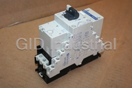
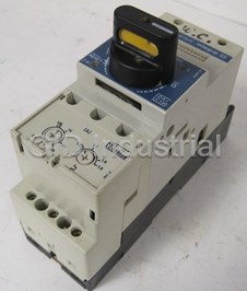
TELEMECANIQUE SX2DV200


Description
Telemecanique SX2DV200 Speed Control Relay Underspeed and Overspeed Control, PNP Sensor or Hard Contact Type Input, 3.2 to 8000 Threshold Range (pulses per minute), 110/220 Vac
Part Number
SX2DV200
Price
Request Quote
Manufacturer
TELEMECANIQUE
Lead Time
Request Quote
Category
COMPONENTS
Specifications
AC power supply
110 Vac (-15%, +10%). 220 Vac (-15%, +10%).
Consumption
2 VA
DC power supply
24 Vdc (19.2 to 27.6 Vdc)
Frequency
50/60 Hz
Housing protection
NEMA 1 (IP20)
Maximum line resistance
200
Maximum pulses per minute
13,000
Minimum duration of the signal
2.3 ms
Minimum input resistance
2.2 k
Minimum input voltage (off)
4 V
Minimum input voltage (on)
11 V
Minimum interval between signals
2.3 ms
Operation
-4 to 122 F (-20 to +50C)
Power Consumption
2 W
Related relay thermal current
5 A
Repeat accuracy (constant voltage)
± 1%
Sensor supply
24 Vdc±15%
Storage
-40 to +185 F (-40 to +85C)
Thermal drift (constant voltage)
± 0.14% per C
Typical input current
10 mA
Voltage drift (constant temperature
± 0.5%
Datasheet

Extracted Text
Speed Control Relays SX2 File 8501 CONTENTS Description . . . . . . . . . . . . . . . . . . . . . . . . . . . . . . . . . . . . . . . . . . . . . . . . . . . . .Page General Information . . . . . . . . . . . . . . . . . . . . . . . . . . . . . . . . . . . . . . . . . . . . . . . . 2-3 SX2DV1 General Information . . . . . . . . . . . . . . . . . . . . . . . . . . . . . . . . . . . . . . . . . . . 4 SX2DV2 General Information . . . . . . . . . . . . . . . . . . . . . . . . . . . . . . . . . . . . . . . . . . . 5 Wiring Diagrams, Approximate Dimensions and Weights. . . . . . . . . . . . . . . . . . . . . . 6 Ordering Information and SpeciŢcations. . . . . . . . . . . . . . . . . . . . . . . . . . . . . . . . . . . 7 Speed Control Relays General Information Properly applied, motion detection devices can: • Decrease downtime • Reduce maintenance • Minimize product damage As production speeds increase and more sophisticated assembly lines or conveyors are used to move products, there is a greater need to monitor and control the speed. This is particularly true since there are more motors, transmissions and belts that can fail, causing downtime. This motion detection can be done in a number of ways, including: • A switch or sensor and an off-delay timer (See 9050 JCK Timers, Catalog 9050CT9601) • A self-contained motion detector (See Sensors, Catalog 9006CT9701, page 102) • A switch or sensor and a speed control relay (described in this catalog) Underspeed Control Underspeed control is used to sense when a shaft or conveyor is going slower than the set speed. When the speed exceeds the set speed, the output contacts change state. They remain energized until an underspeed (slow speed) is detected, or voltage is lost to the relay, then the output contacts change state, returning to their deenergized state. An underspeed relay can be used to detect slippage or breakage of a belt, chain, coupling, or archimedian screw. It can be used to signal the overloading of a grinder or mixer. It can also be used as part of a system to keep doors or gates from opening until moving parts on a machine or robot have stopped moving. Overspeed Control Overspeed control is used when a shaft or conveyor is going faster than the set speed. When the speed exceeds the set speed, the output contacts change state, and they can be used to sound an alarm or shut the machine down. They will remain energized until the speed drops below the low speed setting, then changing state. An overspeed relay can be used to detect breakage of a belt or chain. It can also be used to sequentially start several conveyors. When the Ţrst conveyor reaches a preset speed, then the second conveyor is started, etc. 2 © 1998 Square D All Rights Reserved 1/98 r= 80 Speed Control Relays SX2DV1 General Information Standard Target For Rotating Shafts Target Sensing face of detector A standard target covers a wide speed range and is suitable for use with most sensors. It is a rectangular piece of steel symmetrically mounted across the end of the motor shaft. The dimensions of the standard 0 target are 7.9 in. x 3.5 in. x 0.08 in. (200 mm x 90 mm x 2 mm). To determine the maximum and minimum shaft speed which can be detected using the SX2DV100 or d 96 SX2DV103 and this standard target, use this formula: N = shaft speed Nm = ⁄n == 90 m = number of pulses per minute I n = number of targets (the standard target acts as two targets) The range of the SX2DV100 and SX2DV103 is from 2.2 to 6000 pulses per minute. n = 2 if the standard target is used. N = 6000 / 2 = 3000 rpm Max N = 2.2 / 2 = 1.1 rpm Min Calculating Pulse Duration l = length of target 60·() l + d T = --------------------------- - d = diameter of sensor 2p·Nr· N = shaft speed r = radius from center of shaft to sensor Using the standard target, a 18 mm sensor (for example, XS1M18PA370) and a shaft speed of 1725 rpm: 60·() 90 + 18 6480 T = ---------------------------------------------------- - = 7.5 ms = ---------------------- - = 0.0075 s 2·3.14·1725·80 866, 640 The pulse durations must be: • greater than the SX2DV limit of 2.3 ms • greater than the sensor’s ON and OFF delays Calculating the Interval Between Pulses l = length of target 60·()p·() 2 rn ⁄ –() ld + T = ------------------------------------------------------------------ - d = diameter of sensor 2p·r·N N = shaft speed r = radius from center of shaft to sensor n = number of targets 60()··() 2 3.14 80 ⁄ 2–() 90 + 18 8592 ˙˙ T = --------------------------------------------------------------------------------------------- - = -------------------- - = 9.9 ms = 0.0099 s 2·3.14·80·1725 866,640 Setting and Adjustment To facilitate setup, a selection switch and two potentiometers are on the front of the relay. 1. Select the proper speed range for the SX2DV100 or SX2DV103 relay: • 1 = 2.2 to 60 pulses per minute • 10 = 22 to 600 pulses per minute • 100 = 220 to 6000 pulses per minute 2. Adjust the Speed Threshold Potentiometer to the desired setting. 3. Adjust the Start-up Time Delay Potentiometer to the desired time delay. 3 © 1998 Square D All Rights Reserved 1/98 200 = = · Speed Control Relays SX2DV1 General Information Description of Operation N-Pulses / Minute The SX2DV100 and SX2DV103 relays are used to compare the number of Setting pulses per minute that are being detected to the pulses per minute setting on the relay (using the speed threshold potentiometer and the speed range selector 0 switch). The pulses can be detected from a rotating shaft or from items moving Ti Ti Closed Timed down a conveyor line. Contact Open As soon as power is applied to the relay power supply terminals, the timed Output Energized contacts and output relay contacts close and the LED indicator comes on. Contact De-energized On LED To allow time for the system to attain the preset speed, a timed contact (internal Indicator Off T or external) is used to keep the circuit energized for a preset time period (Ti). If the system is not up to speed by Ti, the relay will shut down the system or motor. If the preset speed is attained by the end of Ti, the output contact will remain closed. If the speed falls below the relay setting at any time after the Ti period is complete, the output contacts open, shutting down the system or motor. The LED indicator is illuminated while the output contact is closed. Pulse Detection 1 2 3 1- Impulse input 2 - 24 VDC power supply The pulses can come from a number or sources. The most common are: inputs and proximity sensor connection • 24 Vdc, 2-wire sensors 0 +24V Ov Ov man auto 3 - Start-up interlocks SX2 DV 100 4 - Speed threshold • 24 Vdc, 3-wire, PNP (sourcing) sensors 4 potentiometer 100 • Hard contacts (limit switches, photoelectric switches, etc.) 5 - Speed range selector 10 5 1 switch 6 6 - "Output relay energized" 7 indicator 14 Volts a.c. 11 7 - Start-up delay 12 110 220 OV 11 12 14 127 240 potentiometer 24 Vdc 2-Wire Sensor 24 Vdc 3-Wire PNP 8 - 110-220 VAC power (Sourcing) Sensor supply inputs Hard Contacts 9 - Relay outputs 8 9 - + + e - e +24V 0V 0V manu auto e +24V 0V 0V manu auto e +24V 0V 0V manu auto Timed Contact Source The Ti timed contact source is either internal or external. The internal source Scale for Start-Up Delay Potentiometer (7) uses the potentiometer on top of the relay to set Ti. The external source uses a normally closed contact of an on-delay timer. Seconds 15 NCTO External Source 10 Jumper Internal Source 5 e +24V 0V 0V manu auto e +24V 0V manu auto 0V 1 A B C D E F G H JKLM 4 © 1998 Square D All Rights Reserved 1/98 Speed Control Relays SX2DV2 General Information Description of Operation Setting and adjustment The SX2DV200 and SX2DV203 relays compare the number of pulses per minute 1- Impulse input 1 2 4 3 5 2 - 24 Vdc power supply detected to the pulses per minute setting on the relay (set with the high speed inputs and proximity sensor connection threshold potentiometer, the speed range selector switch, and the low speed 3 - External interlocking input 0 +24V Ov Ov arm inv 4 - External interlocking input threshold potentiometer). The detected pulses can be from a rotating shaft or SX2 DV 200 (between terminals 3 & 4) 6 items moving down a conveyor line. 5 - Output relay inverting input 100 (between terminals 3 & 5) 10 7 1 6 - High speed threshold 8 Without inv setting potentiometer 9 7 - Speed range selector switch 14 Volts a.c. 11 8 - Output relay energized indicator 12 110 220 Without inv is the most common mode of operation. There is no jumper between OV 11 12 14 127 240 9 - Low speed threshold setting potentiometer the +24 terminal and the inv terminal. When power is applied to the relay 10 - 110-220 Vac power supply inputs between the 0v terminal and either the 110/127 terminal or the 220/240 terminal, 11 - Relay outputs 10 11 the output contact does not change state. When the detected speed reaches the high speed threshold setting, the output relay changes state (energizes). The output will remain energized until the detected speed drops below the low speed threshold setting. The low speed threshold is a percentage (100 to 30%) of the 100 90 high speed threshold. the LED on top of the relay will illuminate whenever the 80 relay is energized. 70 60 With inv 50 40 There is a jumper between the +24v terminal and the inv terminal. When power A B C D E F G H I J K L M is applied to the relay between the 0v terminal and either the 110/127 terminal or the 220/240 terminal, the output contact changes state. When the speed being sensed reaches the high speed threshold setting, the output relay changes state (deenergizes). The output will remain deenergized until the detected speed Jumper drops below the low speed threshold setting. The low speed threshold is a percentage (100 to 30%) of the high speed threshold. The LED on top of the relay will illuminate whenever the relay is energized. Pulse Detection e +24V 0V 0V arm inv The pulses can come from a number or sources. The most common are: • 24 Vdc, 2-wire sensors • 24 Vdc, 3-wire, PNP (sourcing) sensors • Hard contacts (limit switches, photoelectric switches, etc.) N-Pulses / Minute 24 Vdc 2-Wire Sensor 24 Vdc 3-Wire PNP (Sourcing) Sensor Hard Contacts Setting 0 - + e + - Energized De-energized e +24V 0V 0V arm inv e +24V 0V 0V arm inv e +24V 0V 0V arm inv Energized De-energized T If a normally closed timed open contact is wired between arm and 0v as shown below, the output contact will energize immediately, not waiting for the speed to reach the high speed threshold. This can be used to keep the relay energized until the system is up to speed. N-Pulses / Minute Setting NCTO 0 Closed Open Energized De-energized e +24V 0V 0V arm inv 5 © 1998 Square D All Rights Reserved 1/98 RELAY OUTPUT Output "ARM" Relay Contact With Without without Normally INV INV "INV" Closed Timed Contact Time Speed Control Relays Wiring Diagrams and Approximate Dimensions SX2DV100 amd SX2DV103 Wiring Diagrams Using Internal Timed Contact Source Using External Timed Contact Source 14 14 11 11 12 12 Volts, AC Volts, AC 110 220 110 220 0V 11 12 14 11 14 0V 12 127 240 127 240 L1 L2 L1 L2 Start Start Stop OL Stop OL M1 M1 M M SX2DV200 and SX2DV203 Wiring Diagram 14 11 12 Volts, AC 110 220 11 14 0V 12 127 240 L1 L2 Start Stop OL M1 M Approximate Dimensions 2.63 (67) 1.73 4.37 (44) (111) Dimensions are in inches (millimeters). Weight: 11.3 oz (0.32 kg) 6 © 1998 Square D All Rights Reserved 1/98 Speed Control Relays Ordering Information and Application Data Type of Threshold Range Catalog Description Type of Input Supply Voltage Action (pulses per minute) Number 24 Vdc SX2DV103 PNP sensor or hard Underspeed Stopping 2.2 to 6000 contact 110/220 Vac SX2DV100 Underspeed and Stopping 24 Vdc SX2DV203 PNP sensor or hard Overspeed 3.2 to 8000 contact Enabling 110/220 Vac SX2DV200 Control SpeciŢcations 110 Vac (-15%, +10%) AC power supply 220 Vac (-15%, +10%) Frequency 50/60 Hz Consumption 2 VA DC power supply 24 Vdc (19.2 to 27.6 Vdc) Power consumption 2 W Related relay thermal current 5 A Ambient temperature Operation -4 to 122 °F (-20 to +50 °C) Storage -40 to +185 °F (-40 to +85 °C) Housing protection NEMA 1 (IP20) Repeat accuracy (constant voltage)– 1% Thermal drift (constant voltage)– 0.14% per °C Voltage drift (constant temperature– 0.5% Input speciŢcations Sensor supply 24 Vdc –15% Minimum input resistance 2.2 kW Minimum input voltage (on) 11 V Minimum input voltage (off) 4 V Minimum duration of the signal 2.3 ms Minimum interval between signals 2.3 ms Maximum line resistance 200 W Typical input current 10 mA Maximum pulses per minute 13,000 Controllable speed range SX2DV 100/103 2.2 to 6000 pulses per minute SX2DV 200/203 3.2 to 8000 pulses per minute Output relay speciŢcations Voltage 48 Vac 110 Vac 220 Vac 24 Vdc 48 Vdc 1 A 0.5 A Maximum current (IEC) 4 A 2 A 1 A L/R < 5 ms L/R < 5 ms Maximum power 200 VA NEMA rating B150 LED Illuminated when relay is energized 7 © 1998 Square D All Rights Reserved 1/98 Square D Company Square D and are registered trademarks of Square D Company. 8001 Hwy 64 East Knightdale, NC 27545 Catalog No. 8501CT9703 January 1998 © 1998 Square D All Rights Reserved. (919) 266-3671 Replaces 8501CT9601 dated 12/96.
Frequently asked questions
What makes Elite.Parts unique?

What kind of warranty will the SX2DV200 have?
Which carriers does Elite.Parts work with?
Will Elite.Parts sell to me even though I live outside the USA?
I have a preferred payment method. Will Elite.Parts accept it?
Why buy from GID?

Quality
We are industry veterans who take pride in our work

Protection
Avoid the dangers of risky trading in the gray market

Access
Our network of suppliers is ready and at your disposal

Savings
Maintain legacy systems to prevent costly downtime

Speed
Time is of the essence, and we are respectful of yours
Related Products

Telemechanique LC1 D12008 Contactors - IEC Non-Reversing 12A Contactor

Telemecanique LD1 LD030 FC Motor Controller - LD1 LD030 FC
Telemecanique LD1LB030 Starter 575VAC 18AMP 120VAC Coil
Telemecanique LD4 LD030 FC Integral Self-Protected Starter; Open and Enclosed Device
Telemecanique LD4LC130M Integral 32 Non-Reversing Self-Protected Combination Motor Starter

Telemecanique LD5 LB130 Starter -Reversing starter LD5-LB130 120V COIL3 660V 18A with LA1-LB019
Request a Quote

The quote request has been received
Close

Facing challenges or have inquiries? Feel free to contact us!
Call Us +1-469-283-2440
What they say about us
FANTASTIC RESOURCE
One of our top priorities is maintaining our business with precision, and we are constantly looking for affiliates that can help us achieve our goal. With the aid of GID Industrial, our obsolete product management has never been more efficient. They have been a great resource to our company, and have quickly become a go-to supplier on our list!
Bucher Emhart Glass
EXCELLENT SERVICE
With our strict fundamentals and high expectations, we were surprised when we came across GID Industrial and their competitive pricing. When we approached them with our issue, they were incredibly confident in being able to provide us with a seamless solution at the best price for us. GID Industrial quickly understood our needs and provided us with excellent service, as well as fully tested product to ensure what we received would be the right fit for our company.
Fuji
HARD TO FIND A BETTER PROVIDER
Our company provides services to aid in the manufacture of technological products, such as semiconductors and flat panel displays, and often searching for distributors of obsolete product we require can waste time and money. Finding GID Industrial proved to be a great asset to our company, with cost effective solutions and superior knowledge on all of their materials, it’d be hard to find a better provider of obsolete or hard to find products.
Applied Materials
CONSISTENTLY DELIVERS QUALITY SOLUTIONS
Over the years, the equipment used in our company becomes discontinued, but they’re still of great use to us and our customers. Once these products are no longer available through the manufacturer, finding a reliable, quick supplier is a necessity, and luckily for us, GID Industrial has provided the most trustworthy, quality solutions to our obsolete component needs.
Nidec Vamco
TERRIFIC RESOURCE
This company has been a terrific help to us (I work for Trican Well Service) in sourcing the Micron Ram Memory we needed for our Siemens computers. Great service! And great pricing! I know when the product is shipping and when it will arrive, all the way through the ordering process.
Trican Well Service
GO TO SOURCE
When I can't find an obsolete part, I first call GID and they'll come up with my parts every time. Great customer service and follow up as well. Scott emails me from time to time to touch base and see if we're having trouble finding something.....which is often with our 25 yr old equipment.
ConAgra Foods