

 Manufacturers
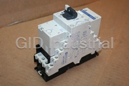
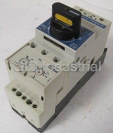
TELEMECANIQUE LD1LB030
Description
Telemecanique LD1LB030 Starter 575VAC 18AMP 120VAC Coil
Part Number
LD1LB030
Price
Request Quote
Manufacturer
TELEMECANIQUE
Lead Time
Request Quote
Category
COMPONENTS
Specifications
Approvals
ASTA, BS, CSA, DEMKO, IEC, NEMKO, SEMKO, UL, VDE
Magnetic Protection
Fixed, 15 times maximum thermal current
Number of Poles
3
Rated Breaking Capacity
42 KA at 480 Vac
Rated Operational Current for AC-3 Duty
18 A
Features
- 18, 32, or 63 ampere ratings.
- Control direct from PLC or PC with optional interface modules.
- Current-limiting short-circuit protection provides 42 kA interrupt rating.
- Meets “Total Coordination” requirements of IEC 947-6 — no damage to contactor or overload relay, and no welding of contacts after interruption of short-circuit faults.
- Minimum 1.5 million operation life expectancy.
- NEMA Type 1 and 12 enclosed combination motor controllers and open style combination motor controllers both available.
- Non-reversing and reversing combination motor controllers available in
- Padlockable isolation knob.
- Proven reliability — even after exposure to multiple short-circuit faults!
- UL listed as a Type E combination motor controller.
- UL veri?ed to meet “Type 2” coordination protection per IEC 947-4.
Datasheet

Extracted Text
INTEGRAL™ Self-Protected Combination Motor Controllers Class 8539 CONTENTS Description Page Product Descriptions. . . . . . . . . . . . . . . . . . . . . . . . . . . . . . . . . . . . . . . . . . . . . . . . 3-5 Selection . . . . . . . . . . . . . . . . . . . . . . . . . . . . . . . . . . . . . . . . . . . . . . . . . . . . . . . . 6-20 Application and General Information. . . . . . . . . . . . . . . . . . . . . . . . . . . . . . . . . . 21-27 SpeciŢcations . . . . . . . . . . . . . . . . . . . . . . . . . . . . . . . . . . . . . . . . . . . . . . . . . . . 28-41 Wiring Diagrams . . . . . . . . . . . . . . . . . . . . . . . . . . . . . . . . . . . . . . . . . . . . . . . . . 42-46 Schneider Electric Brands Dimensions . . . . . . . . . . . . . . . . . . . . . . . . . . . . . . . . . . . . . . . . . . . . . . . . . . . . . 47-51 INTEGRAL™ Self-Protected Combination Motor Controllers 2 © 2000 Schneider Electric All Rights Reserved 01/00 INTEGRAL™ Self-Protected Combination Motor Controllers Product Description COMBINATION MOTOR CONTROL IN ONE COMPACT PACKAGE! The INTEGRAL™ Self-Protected Combination Motor Controller (CMC) combines all the functions of a disconnect, circuit breaker, contactor, and overload relay in a coordinated motor controller. A wide variety of easy-to- install auxiliary blocks and interface modules provides powerful communication and control capabilities. As much as 60% less panel space is required by the INTEGRAL CMC as compared to traditional combination motor control circuit installations. In addition, installation and wiring time is dramatically reduced — simply snap the INTEGRAL onto a 35 mm DIN rail and connect load and line side wires. The entire family of INTEGRAL CMCs have proven their reliability and effectiveness in thousands of applications worldwide. By installing the Integral 18 INTEGRAL Self-Protected CMC, you are implementing the latest in motor control and protection technology, and assuring the lowest installed cost of any motor control scheme. Features • Non-reversing and reversing combination motor controllers available in 18, 32, or 63 ampere ratings. • NEMA Type 1 and 12 enclosed combination motor controllers and open style combination motor controllers both available. • Current-limiting short-circuit protection provides 42 kA interrupt rating. • UL listed as a Type E combination motor controller. • UL veriŢed to meet “Type 2” coordination protection per IEC 947-4. • Meets “Total Coordination” requirements of IEC 947-6 — no damage to contactor or overload relay, and no welding of contacts after interruption of short-circuit faults. • Padlockable isolation knob. Integral 32 • Minimum 1.5 million operation life expectancy. • Proven reliability — even after exposure to multiple short-circuit faults! • Control direct from PLC or PC with optional interface modules. Integral 63 3 © 2000 Schneider Electric All Rights Reserved 01/00 INTEGRAL™ Self-Protected Combination Motor Controllers Product Description INTEGRAL 18 INTEGRAL 32 LD1LB030• LD5LB030• LD1LC030• LD4LC030• LD5LC130• + + + + + LB1LB03P•• LB1LB03P••LB1LC03M•• LB1LC03M•• LB1LC03M•• Rated Operational Current 18 A 32 A for AC-3 Duty Rated Breaking Capacity 42 KA at 480 Vac 42 KA at 480 Vac Approvals ASTA, BS, CSA, DEMKO, IEC, NEMKO, SEMKO, UL, VDE ASTA, BS, CSA, DEMKO, IEC, NEMKO, SEMKO, UL, VDE Number of Poles33 Protection Module LB1LB03P•• LB1LC03M•• Magnetic Protection Fixed, 15 times maximum thermal current Adjustable, 6 to 12 times maximum thermal current Overload Protection 0.1 to 0.16 A: P01 0.16 to 0.25 A P02 0.25 to 0.4 A P03 0.25 to 0.4 A M03 0.4 to 0.63 A P04 0.4 to 0.63 A M04 0.63 to 1.0 A P05 0.63 to 1.0 A M05 1.0 to 1.6 A P06 1.0 to 1.6 A M06 1.6 to 2.5 A P07 1.6 to 2.5 A M07 2.5 to 4.0 A P08 2.5 to 4.0 A M08 4.0 to 6.0 A P10 4.0 to 6.3 A M10 6.0 to 10.0 A P13 6.3 to 10.0 A M13 10.0 to 16.0 A P17 10.0 to 16.0 A P17 12.0 to 18.0 A P21 – – 16.0 to 25.0 A M22 – 23.0 to 32.0 A M23 4 © 2000 Schneider Electric All Rights Reserved 01/00 INTEGRAL™ Self-Protected Combination Motor Controllers Product Description INTEGRAL 63 LD1LC030• LD4LC030• LD5LC130• + + + LB1LC03M•• LB1LC03M•• LB1LC03M•• Rated Operational Current 63 A for AC-3 Duty Rated Breaking Capacity 42 KA at 480 Vac Approvals ASTA, BS, CSA, DEMKO, IEC, NEMKO, SEMKO, UL, VDE Number of Poles 3 Protection Module LB1LD03M•• Magnetic Protection Adjustable, 6 to 12 times maximum thermal current Overload Protection 10.0 to 13.0 A M16 13.0 to 18.0 A M21 18.0 to 25.0 A M22 23.0 to 32.0 A M53 28.0 to 40.0 A M55 35.0 to 50.0 A M57 45.0 to 63.0 A M61 5 © 2000 Schneider Electric All Rights Reserved 01/00 INTEGRAL™ Self-Protected Combination Motor Controllers Selection To order an INTEGRAL CMC, complete these four steps: 1. Select the correct combination motor controller from Table 1A (open) or Table 1B (enclosed). 2. Complete the catalog number by adding the coil voltage code from Table 2. 3. Choose the appropriate protection module from Table 3. 4. For enclosed combination motor controllers only, select any desired INSTA-KITS™ or factory modiŢcations from Table on page 20. For factory modiŢcation, add the “form” number to the end of the catalog number. Table 1A: Open Style INTEGRAL CMC Base Unit Selection Table Continuous Maximum 3-Phase HP Rating With Isolator Without Isolator LD1LB030¥ Current Rating Amperes 230 V 460 V 575 V Catalog Number Catalog Number Non-Reversing 18 5 10 15 LD1LB030* N/A 32 10 20 30 LD4LC030* LD1LC030 l 63 20 40 60 LD4LD030* LD1LD030 l Reversing 18 5 10 15 LD5LB130* N/A 32 10 20 30 LD5LC030* N/A 63 20 40 60 LD5LD030* N/A Table 1B: Enclosed INTEGRAL CMC Selection Table LD5LB130¥ Continuous Maximum 3-Phase HP Rating Type 1 Enclosure Type 12 Enclosure Current Rating Amperes 230 V 460 V 575 V Catalog Number Catalog Number Non-Reversing 18 5 10 15 LE1UI1846 lLE1UI1847 l 32 10 20 20 LE1UI3246 lLE1UI3247 l 63 20 40 60 LE1UI6346 l LE1UI6347 l Reversing 18 5 10 15 LE2UI1846 lLE2UI1847 l LD4LC030• 32 10 20 20 LE2UI3246 lLE2UI3247 l 63 20 40 60 LE2UI6346 lLE2UI6347 l lComplete the catalog number by adding the voltage code from Table 2 Table 2: Coil Voltage Codes Control Voltage Frequency INTEGRAL 24 48 110 120 220 240 380 415 480 600 Hz 50 B E F - M UQN - - I18 60 BC D K FC LC MC - - N S DC n BD --------- LD5LC030¥ 50 B E F - M UQN - - I32 60 BC D FC FC MC MC - - Q S DC n BD ED FD ------- 50 B E F - M UQN - - I63 60 BC CE K FC LC MC - - Q S DC n BD ED FD ------- n INTEGRAL Base Units ordered with DC voltage code (BD, ED or FD) are shipped with LA1L*080*D Voltage Converter Module already installed. Open Product Enclosed Product Open INTEGRAL CMC Dimensions. . . . . . . . . . page 48 File E164871 File E163364 Enclosed INTEGRAL CMC Dimensions. . . . . . . page 51 CCN NKJH CCN NKJH NKJH7 NKJH7 LD4LD030¥ File LR 43364 File LR 105062 Class 3211 08 Class 3211 08 6 © 2000 Schneider Electric All Rights Reserved 01/00 90° 30° INTEGRAL™ Self-Protected Combination Motor Controllers Selection Table 3: Overload Protection Modules (Class 10, Ambient Compensated) Standard Module with Thermal Setting Magnetic Setting Magnetic only Thermal & Magnetic Trip Range, Amperes c Range, Amperes Module Catalog No. For 18 Ampere models 0.1 - 0.16 – LB1LB03P01 N/A 0.16 - 0.25 – LB1LB03P02 N/A 0.25 - 0.4 – LB1LB03P03 N/A 0.4 - 0.63 – LB1LB03P04 N/A 0.63 - 1 – LB1LB03P05 N/A 1 - 1.6 – LB1LB03P06 N/A 1.6 - 2.5 – LB1LB03P07 N/A 2.5 - 4 – LB1LB03P08 N/A 4 - 6 – LB1LB03P10 N/A 6 - 10 – LB1LB03P13 N/A LB1LB03P05 10 - 16 – LB1LB03P17 N/A 12 - 18 – LB1LB03P21 N/A For 32 Ampere models 0.25 - 0.40 2.4 - 4.8 LB1LC03M03 LB6LC03M03 0.40 - 0.63 3.8 - 7.6 LB1LC03M04 LB6LC03M04 0.63 - 1.0 6.0 - 12 LB1LC03M05 LB6LC03M05 1.0 - 1.6 9.5 - 19 LB1LC03M06 LB6LC03M06 1.6 - 2.5 15 - 30 LB1LC03M07 LB6LC03M07 2.5 - 4.0 24 - 48 LB1LC03M08 LB6LC03M08 4.0 - 6.3 38 - 76 LB1LC03M10 LB6LC03M10 6.3 - 10 60 - 120 LB1LC03M13 LB6LC03M13 10 - 16 95 - 190 LB1LC03M17 LB6LC03M17 LB1LC03M22 16 - 25 150 - 300 LB1LC03M22 LB6LC03M22 23 - 32 190 - 380 LB1LC03M53 LB6LC03M53 For 63 Ampere models 18 - 25 150 - 300 LB1LD03M22 LB6LD03M22 23 - 32 190 - 380 LB1LD03M53 LB6LD03M53 28 - 40 240 - 480 LB1LD03M55 LB6LD03M55 35 - 50 300 - 600 LB1LD03M57 LB6LD03M57 45 - 63 380 - 760 LB1LD03M61 LB6LD03M61 c Thermal settings are based on motors with a service factor (S.F.) of 1.0. SpeciŢcations LB1LD03M57 Operating Positions: UL Listed and CSA certiŢed Conforms to IEC standards Shock resistance - 8 g (Duration of impulse: 11 ms) Vibration resistance - 3 g (5 to 150 Hz) AC control circuit temperature limits: Storage -40 to +176 °F/-40 to +80 °C Rated voltage - 600 Vac Operation -13 to +104 °F/-25 to +70 °C Rated thermal current - 18 A (INTEGRAL 18), 32 A (INTEGRAL 32), 63 A (INTEGRAL 63) Interrupting current at 480 Vac: 42 kA ms Fixed magnetic trip is set at approximately 15 times full load current (FLC) Mechanical life: Operating current of magnetic trip is approximately INTEGRAL 18 20 million operations 15 times maximum thermal trip (non-adjustable setting) INTEGRAL 32 10 million operations INTEGRAL 63 5 million operations File E164871 File LR 43364 CCN NKJH Class 3211 08 NKJH7 7 © 2000 Schneider Electric All Rights Reserved 01/00 30° 90° INTEGRAL™ Self-Protected Combination Motor Controllers INTEGRAL 18 Accessories LA1LB019 LA1LB001 LD5LB LA1LB017 LA1LB001 LA1LB021 LA1LB0311 LA1LB015 LD1LB LA1LB0211 LA1LB034 LA1LB031 LA1LB0341 8 © 2000 Schneider Electric All Rights Reserved 01/00 AUTO O AUTO O AUTO O TRIP. + TRIP. + TRIP. + INTEGRAL™ Self-Protected Combination Motor Controllers INTEGRAL 18 Accessories Auxiliary Contact Blocks for the INTEGRAL 18 CMC For Use On Mounting Location Type and Number of Contacts per Block Contact Type Catalog Number Block of 5 instantaneous contacts 2 N/O + 1 N/C Right Side 3 signal “contactor state” LA1LB015 1 N/O + 1 N/C 2 signal “tripped” status Block of 3 instantaneous contacts 1 N/O + 1 N/C Right Side 2 signal “contactor state” LA1LB017 1 N/O 1 signal “tripped” status LD1 or LD5 Block of 3 instantaneous contacts 1 N/O + 1 N/C Right Side 2 signal “contactor state” LA1LB019 1 N/C 1 signal “tripped” status Complementary auxiliary block Left or Right Side 1 N/C LA1LB001a 1 signal “contactor state” Left Side 2 signal operating handle not in “Auto” position 2 N/O LA1LB031 Left Side 2 signal operating handle not in “Auto” position 1 N/O + 1 N/C LA1LB0311 Block of 3 instantaneous contacts 2 N/O Left Side 2 signal operating handle not in “Auto” position LA1LB034 LD1 1 N/O + 1 N/C LD1LB03FC + LB1LB03P01 2 signals “tripped on short circuit” status Block of 3 instantaneous contacts 1 N/O + 1 N/C Left Side 2 signal operating handle not in “Auto” position LA1LB0341 1 N/O + 1 N/C 2 signals “tripped on short circuit” status Block of 5 instantaneous contacts 2 N/O + 1 N/C Left Side 3 signal “contactor state” LA1LB021 2 N/O 2 signal operating handle not in “Auto” position LD5 Block of 5 instantaneous contacts 2 N/O + 1 N/C Left Side 3 signal “contactor state” LA1LB0211 1 N/O + 1 N/C 2 signal operating handle not in “Auto” position a Use of auxiliary contact LA1LB001 requires combination with contact block LA1LB015, LA1LB021, LA1LB017, or LA1LB019. File E164871 CCN NKJH NKJH7 File LR 43364 Class 3211 08 9 © 2000 Schneider Electric All Rights Reserved 01/00 INTEGRAL™ Self-Protected Combination Motor Controllers INTEGRAL 32/63 Accessories LA1LC020 LA1LC021 LA1LC031 LA1LC07 l l LD5LC,LD LA1LC001 LA1LC012 LA1LC052 l LA1LC030 (LD4) LA1LC001 LA1LC030 (LD4) LD1LC,LD LD4LC,LD LA1LC010 LA1LC025 10 © 2000 Schneider Electric All Rights Reserved 01/00 AUTO O AUTO RESET AUTO O TRIP. + TRIP. + TRIP. + INTEGRAL™ Self-Protected Combination Motor Controllers INTEGRAL 32/63 Accessories Auxiliary Contact Blocks for the INTEGRAL 32/63 CMC For Mounting Type and Number of Contact Type Catalog Number Use On Location Contacts per Block 2 N/O + 1 N/C Block of 6 instantaneous contacts 1 N/O-N/C 3 signal “contactor state” (form C contact) Right Side 1 signal “tripped on short circuit” 1 N/O-N/C LA1LC010 1 signal “tripped” (form C contact) 1 signal “not in Auto position” 1 N/O-N/C (form C contact) Block of 5 instantaneous contacts 3 signal “contactor state” 2 N/O + 1 N/C Right Side LA1LC012 1 signal “tripped on short circuit” 1 N/O 1 N/O 1 signal “tripped” LD1, LD4 or LD5 Block of 4 instantaneous contacts 2 N/O + 1 N/C LA1LC030 Right Side 3 signal “contactor state” 1 N/O or 1 N/C, LA1LC025 1 signal “tripped” User Selectable Block of 3 instantaneous contacts Right Side 2 N/O + 1 N/C LA1LC020 3 signal “contactor state” Complementary auxiliary block Left or Right Side 1 N/C LA1LC001q 1 signal “contactor state” LD4 Left Side Block of 1 “control circuit isolation” contact 1 N/O LA1LC030 Block of 3 instantaneous contacts Left Side 2 N/O + 1 N/C LA1LC021 3 signal “contactor state” LD5 Left Side Block of 2 “control circuit isolation” contact 2 N/O LA1LC031q q See table below. Complementary blocks LA1LC001 and LA1LC031, as well as LA1LC052** reset modules LA1LC012 and LA1LC07** trip modules on page 12 must be used with an additional auxiliary block. This following table shows all allowable combinations. Possible Combinations of Auxiliary Contact Blocks for the INTEGRAL 32/63 CMC LA1LC001 LA1LC07** LA1LC052* LA1LC031 LA1LC010 Block of 6 auxiliary contacts Right Side √ √ LA1LC012 Block of 5 auxiliary contacts Right Side √ f √ √ f LA1LC025 Block of 4 auxiliary contacts Right Side ˆ LC4LC030+ LB1LC03M22+ LA1LC030+ LA1LC021 Block of 3 auxiliary contacts Left Side ˆ t √t LA1LC010+ LA1LC070F f Only one attachment may be added -- either LA1LC001 or LA1LC052 t Only one attachment may be added -- either LA1LC001 or LA1LC031 File E164871 CCN NKJH ® NKJH7 File LR 43364 Class 3211 08 3211 04 11 © 2000 Schneider Electric All Rights Reserved 01/00 INTEGRAL™ Self-Protected Combination Motor Controllers INTEGRAL 32/63 Accessories LA1LC020 LA1LC021 LA1LC031 LA1LC07 l l LD5LC,LD LA1LC001 LA1LC012 LA1LC052 l LA1LC030 (LD4) LA1LC030 LA1LC001 (LD4) LD1LC,LD LD4LC,LD LA1LC010 LA1LC025 12 © 2000 Schneider Electric All Rights Reserved 01/00 AUTO O AUTO RESET AUTO O TRIP. + TRIP. + TRIP. + INTEGRAL™ Self-Protected Combination Motor Controllers INTEGRAL 32/63 Accessories The shunt and undervoltage trip modules are for use with any 32 A or 63 A INTEGRAL CMC Ţtted with either an LA1LC010 or LA1LC012 add-on block. Shunt and Undervoltage Trip Modules Description Trip SpeciŢcations Catalog Number Time Delay (0.2 seconds) LA1LC070k Undervoltage Trip Module LA1LC070F Instantaneous LA1LC072k Shunt Trip Module Instantaneous LA1LC071k k Complete the catalog number with the letter shown below for the required coil voltage Volts 24 48 110 120 220 240 380 415 440 50 Hz B E F - M UQN N 60 Hz BE F F M M Q - N The remote reset modules are for use with any 32 A or 63 A INTEGRAL CMC Ţtted with either an LA1LC010 or LA1LC012 add-on block. Remote Reset Modules Description Control Voltage Catalog Number 24 V 50/60 Hz LA1LC052B 42 V 50 Hz LA1LC052F LA1LC052E 48 V 50/60 Hz Remote Reset Module n 100/127 V 50/60 Hz LA1LC052F 200/240 V 50/60 Hz LA1LC052M nWhen adding a remote reset module to a LE•UI••• enclosed device (page 6), an oversized enclosure is required. File E164871 CCN NKJH ® NKJH7 File LR 43364 Class 3211 08 13 © 2000 Schneider Electric All Rights Reserved 01/00 INTEGRAL™ Self-Protected Combination Motor Controllers INTEGRAL 18/32/63 Accessories LA4DA2 l LA4DE2 l LA9D09982 LA4DR l U LA4DM l LA4DL l LA4DT l U LA1LB080BD LA4DWB LA4DF l LD5LB LD1LB LA9D09982 LA1L l 080 l D LA1L l 180BD LA1L l 580 l D LD5LC,LD LD1LC,LD LD4LC,LD 14 © 2000 Schneider Electric All Rights Reserved 01/00 TRIP. TRIP. + TRIP. + AUTO + O AUTO O AUTO O AUTO TRIP. + TRIP. + RESET AUTO TRIP. + O INTEGRAL™ Self-Protected Combination Motor Controllers INTEGRAL 18/32/63 Accessories The top-mounted, add-on voltage converter modules are required to allow operation of an INTEGRAL CMC with DC control voltage. The converters may only be used with the coils shown in the table below. NOTE: When INTEGRAL CMCs are factory ordered with a DC coil code (from Table 1A / 1B and Table 2, Page 6), these converter modules need not be ordered separately. Voltage Converter Modules c a Description Nominal Voltage For Use With Coils Catalog Number INTEGRAL 18 Converter Module 24 Vdc LX1LB024 LA1LB080BD 24 Vdc LX1LC0249 LA1LC080BD INTEGRAL 32 Converter Module 48 Vdc LX1LC0489 LA1LC080ED 110 Vdc LX1LC1109 LA1LC080FD 24 Vdc LX1LD0249 LA1LD080BD INTEGRAL 63 Converter Module 48 Vdc LX1LD0489 LA1LD080ED LA1LC180BD 110 Vdc LX1LD1109 LA1LD080FD c When using a rectiŢed AC supply, ripple must not exceed 14%. a Reversing INTEGRAL CMCs require use of two converter modules. The interface modules allow INTEGRAL CMCs to be energized from low voltage and low current signals. Solid state and mechanical relay versions are both available. The “relay plus manual override” version includes a slide switch for manually energizing the contactor. Interface Modules Operational Description q Type Input Voltage Catalog Number Voltage INTEGRAL 18 Interface Module Solid State Relay 5 to 24 Vdc 24 to 250 Vac LA4DWB 24 Vdc 24 to 250 Vac LA4DFB Mechanical Relay File E164871 48 Vdc 24 to 250 Vac LA4DFE CCN NKJH ® NKJH7 24 Vdc 24 to 250 Vac LA4DLB Mechanical Relay plus manual override 48 Vdc 24 to 250 Vac LA4DLE File LR 43364 Class 3211 08 Solid State Relay 5 to 24 Vdc 24 to 240 Vac LA1LC180BD INTEGRAL 32 Interface Module 24 Vdc 24 to 240 Vac LA1LC580BD Mechanical Relay 48 Vdc 24 to 240 Vac LA1LC580ED Solid State Relay 5 to 24 Vdc 24 to 240 Vac LA1LD180BD INTEGRAL 63 Interface Module 24 Vdc 24 to 240 Vac LA1LD580BD Mechanical Relay 48 Vdc 24 to 240 Vac LA1LD580ED q Reversing INTEGRAL CMCs require use of two interface modules. 15 © 2000 Schneider Electric All Rights Reserved 01/00 INTEGRAL™ Self-Protected Combination Motor Controllers INTEGRAL 18/32/63 Accessories LA4DA2 l LA4DE2 l LA9D09982 LA4DR l U LA4DM l LA4DL l LA4DT l U LA1LB080BD LA4DWB LA4DF l LD5LB LD1LB LA9D09982 LA1L l 080 l D LA1L l 180BD LA1L l 580 l D LD5LC,LD LD1LC,LD LD4LC,LD 16 © 2000 Schneider Electric All Rights Reserved 01/00 TRIP. TRIP. + TRIP. + AUTO + O AUTO O AUTO O AUTO TRIP. + TRIP. + RESET AUTO TRIP. + O INTEGRAL™ Self-Protected Combination Motor Controllers Accessories The control modules allow local or remote operation of the 18 A INTEGRAL CMC. The module includes a slide switch to change from automatic (remote) operation to manual (local) operation. When in manual mode, a separate dial allows the user to locally energize and de-energize the combination motor controller. “Automatic - Manual - Stop” Control Module (for INTEGRAL 18 only) Description Control Voltage Catalog Number 24 - 100 Vac LA4DMK Auto- Manual-Stop Module 100 - 250 Vac LA4DMU LA4DMU These electronic timer modules delay the energization or de-energization of the 18 ampere INTEGRAL CMC. Electronic Timer Module (for INTEGRAL 18 only) Description Time DelayOperational Voltage c 50/60 Hz AC Catalog Number 0.1 to 2 sec. 24 to 240 Vac LA4DT0U On-Delay Timer Module 1.5 to 30 sec. 24 to 240 Vac LA4DT2U 25 to 500 sec. 24 to 240 Vac LA4DT4U 0.1 to 2 sec. 24 to 240 Vac LA4DR0U LA4DROU Off-Delay Timer Module 1.5 to 30 sec. 24 to 240 Vac LA4DR2U 25 to 500 sec. 24 to 240 Vac LA4DR4U c For 24 Vac operation, INTEGRAL CMCs requires a 21 volt coil, see coil table page 19. The coil suppressor modules reduce electrical noise generated by operation of the INTEGRAL CMC. Coil Suppressor Modules Description For Use With Operational Voltage 50/60 Hz AC Catalog Number LA4DA2U 24 to 48 Vac LA4DA2E RC Circuit 18A INTEGRAL 50 to 127 Vac LA4DA2G 110 to 250 Vac LA4DA2U 24 to 48 Vac LA4DE2E Varistor 18A INTEGRAL 50 to 127 Vac LA4DE2G 110 to 250 Vac LA4DE2E RC Circuit 18A, 32A, 63A INTEGRAL 24 to 250 Vac LA9D09982 File E164353 CCN NKJH ® File LR 43364 Class 3211 03 17 © 2000 Schneider Electric All Rights Reserved 01/00 INTEGRAL™ Self-Protected Combination Motor Controllers INTEGRAL 18/32/63 Accessories Other Accessories Description Usage Catalog Number Attaches to front face of INTEGRAL 18 to allow attachment Control Knob Padlocking Kit LA9LB390 of up to 3 padlocks Control Circuit Test Device Used on INTEGRAL 18 only LA9LB398 To mount I18 or I32 on two 32 mm Omega rails LA9LC010 LA9LB930 Mounting Plate To mount I32 on one 75mm or two 32mm Omega rails LA9LC012 To mount I63 on one 75mm Omega rail LA9LD010 DIN Rail, 35 mm AM1DE200 DIN Rail, 75 mm AM1DL201 . Connection Accessories (INTEGRAL 18 Units Only) Description Catalog Number Set of 63 A 3-pole busbars to supply an additional INTEGRAL LA9LB930 (2) Terminal to supply one or more LA9LB930 busbar sets; cables connected to top GV1G09 (1) GV1G09 Terminal to supply one or more LA9LB930 busbar sets; cables connected to bottom LA9LB960 (2) Through the Door Operators (IP54) Description For Use With Knob Color Catalog Number Red LA9LB330 I18 (LD1 or LD5) Black LA9LB331 Red LA9LC330 Adjustable Depth Operator t I32, I63 (LD1) (from 0 to 185mm depth) Black LA9LC331 Red LA9LC530 I32, I63 (LD4 or LD5) Black LA9LC531 LA9LB960 Red LA9LB320 I18 (LD1 or LD5) Black LA9LB321 Red LA9LC320 Fixed Depth Operator t I32, I63 (LD1) Black LA9LC321 Red LA9LC520 I32, I63 (LD4 or LD5) Black LA9LC521 t See page 49 for mounting dimensions. LA9LC701 Protection Accessories Description For use with Sold in Lots of Catalog Number INTEGRAL 32 5 LA9LC701 Finger Protection Cover for power terminals (L1, L2, L3) INTEGRAL 63 5 LA9LD701 Anti-tamper cover for: INTEGRAL 18 1 LA1LB090 protection module LB n protection module LC or LD INTEGRAL 32 or 63 1 LA1LC090 nFor use with trip modules manufactured after January 1, 1998. LA9Lk090 (1) (2) File E164871 File E164864 CCN NKJH CCN NLRV ® ® NKJH7 File LR 81630 File LR 43364 Class 3211 05 Class 3211 08 18 © 2000 Schneider Electric All Rights Reserved 01/00 INTEGRAL™ Self-Protected Combination Motor Controllers INTEGRAL 18/32/63 Accessories AC Coils DC Coils c Nominal 60 Hz Coil 50 Hz Coil Nominal Converter DC Coil Voltage Cat. No. Cat. No. Voltage Cat. No. Cat. No. 18 A Models 18 A model 21 LX1LB019 LX1LB021 24 LA1LB080BD LX1LB024 24 LX1LB021 LX1LB024 32 A models 36 LX1LB032 – 24 LA1LC080BD LX1LC0249 LX1LBkkk 42 – LX1LB042 48 LA1LC080ED LX1LC0489 48 LX1LB042 LX1LB048 110 LA1LC080FD LX1LC1109 110 LX1LB100 LX1LB110 63 A models 115/120 LX1LB105 – 24 LA1LD080BD LX1LD0249 127 – LX1LB127 48 LA1LD080ED LX1LD0489 220 LX1LB200 LX1LB220 110 LA1LD080FD LX1LD1109 c INTEGRAL CMCs can operate on D.C. control 230/240 LX1LB210 – LX1LCkkk voltage when Ţtted with a coil and converter from the table above. 240 – LX1LB240 380 – LX1LB380 415 – LX1LB415 440 LX1LB380 LX1LB440 460/480 LX1LB415 – 500 – LX1LB500 575/600 LX1 LB500 – 660 – LX1LB660 32 A models 24 LX1LC020 LX1LC024 LX1LDkkk 110 - LX1LC110 120 LX1LC100 - 220 LX1LC190 LX1LC220 240 LX1LC190 LX1LC240 480 LX1LC380 - 63 A models 24 LX1LD020 LX1LD024 110 LX1LD090 LX1LD110 120 LX1LD100 - 220 LX1LD180 LX1LD220 240 LX1LD190 LX1LD240 480 LX1LD380 - 19 © 2000 Schneider Electric All Rights Reserved 01/00 INTEGRAL™ Self-Protected Combination Motor Controllers Accessories Pilot devices and control transformers for enclosed INTEGRAL CMCs can be ordered in one of two convenient ways. Telemecanique INSTA-KITS™ may be installed at our factory by attaching the form number sufŢx from the table below to the end of the catalog number selected in Table 1B on page 6. Alternatively, the INSTA-KIT may be ordered separately by choosing the appropriate catalog number from the right-most column below. INSTA-KITS are easily installed in the Ţeld by removing the existing cover plate on the enclosure, installing the INSTA-KIT plate, and plugging the pre-terminated wires into its mating connector. Table 4: INSTA-KITS™ Selection. Factory-Installed INSTA-KIT Description Form Numbera Catalog Number On/Off Selector Switch C6 LA9C6 Hand-Off-Auto Selector Switch C LA9C Green Pilot Light P2 q LA9P12 q Red Pilot Light P1 q LA9P12 q Green Transformer Pilot Light P52 q LA9P5152* c q Red Transformer Pilot Light P51 q LA9P5152* c q Start/Stop Pushbutton A LA9A Start/Stop (Mushroom Head) Pushbuttons A22 LA9A2 LA9C6P12 I/O (Start/Stop) Pushbutton A6 — On/Off Selector Switch with Green Pilot Light C6P2 LA9C6P12 On/Off Selector Switch with Red Pilot Light C6P1 LA9C6P12 Hand-Off-Auto Selector Switch with Green Pilot Light CP2 LA9CP12 Hand-Off-Auto Selector Switch with Red Pilot Light CP1 LA9CP12 H-O-A Selector Switch with Green Transformer Pilot Light CP52 LA9CP5152t c H-O-A Selector Switch with Red Transformer Pilot Light CP51 LA9CP5152t c Forward-Reverse-Stop Pushbuttons A1 LA9A1 Start/Stop Pushbutton with Green Pilot Light AP2 LA9AP12 Start/Stop Pushbutton with Red Pilot Light AP1 LA9AP12 Start/Stop Pushbutton with Green Transformer Pilot Light AP52 LA9AP5152t c Start/Stop Pushbutton with Red Transformer Pilot Light AP51 LA9AP5152t c Standard Control Transformer with Top Mounted Fuse Block: 50 VA Transformer (Standard size for INTEGRAL 18 and 32) FF4TKF50f LA9FF4TKF50f 100 VA Transformer (Extra capacity for I18 or I32; Std. capacity for I63) FF4TKF100f LA9FF4TKF100f 150 VA Transformer (Extra capacity for INTEGRAL 63) FF4TKF150f LA9FF4TKF150f Local/Remote Adapter - Three Wire q — LA93W Local/Remote Adapter - Four Wire q — LA94W Local/Remote Adapter - Five Wire q — LA95W Local/Remote Adapter - Seven Wire q — LA97W All except Transformers Fuse Kit for Remote e — LA9FK File E14839 f Complete the form number or catalog number with one of the following voltage codes: CCN NKCR NKCR7 ® Voltage D1 D2 D3 D14 D33 Primary 480/240 480/240 208 208 380/400/415 Secondary 120 24 120 24 115/230 File LR 105062 c Replace t with the sufŢx letter corresponding to the pilot light voltage. Class 3211 02 Voltage 24 V 120 V 208/240 V 480 V SufŢx LetterBKPW Transformers a For factory modiŢcation, add form number to the end of the catalog number. File E 61239 qkLA93W required when START/STOP pushbutton remote station is used in conjunction with START/STOP CCN XPTQ local control OR if local pilot light only is used. XPTQ7 ® kLA94W required when FOR/REV/STOP is required for both local and remote control. kLA95W required when START/STOP pushbutton with pilot light remote station OR pilot light only remote is used with START/STOP pushbutton local control. kLA97W required for remote control only applications. e Required when local/remote adapters are used. 20 © 2000 Schneider Electric All Rights Reserved 01/00 INTEGRAL™ Self-Protected Combination Motor Controllers INTEGRAL 18/32/63 Technical Data Mechanical and Electrical Life Curves Based on Utilization Category and Number of Switching Cycles Alternating Current Utilization Category AC-3 Operating voltage 200 V 230 V 460 V 575 V Operating current at q £ 104 °F (40 °C) INTEGRAL 18 18 A 18 A 18 A 18 A INTEGRAL 32 32 A 32 A 32 A 32 A INTEGRAL 63 63 A 63 A 63 A 63 A Rated horsepower at q £ 104 °F (40 °C) INTEGRAL 18 5 hp 5 hp 10 hp 15 hp INTEGRAL 32 10 hp 10 hp 20 hp 30 hp INTEGRAL 63 20 hp 20 hp 40 hp 60 hp Electrical life Motor control and protection in utilization categories AC-2, AC-3, AC-4, at Ue £ 400 volts Current Breaking Limit INTEGRAL 18 INTEGRAL 32 and 63 Millions of operating cycles Millions of operating cycles 20 20 4 3 2 1 3 2 1 (32A) 10 10 4 8 8 (63A) 6 6 1 5 5 4 4 2 2 1.5 1.5 1 1 0.8 0.8 0.6 0.6 0.4 0.4 0.2 0.2 0.1 0.1 0.08 0.08 0.06 0.06 0.04 0.04 0.02 0.02 0.01 0.01 1 1.523 45678 10 20 40 60 100 150 300 1 1.523 4567 9 20 40 60 80 150 200 300 8 10 9 18 80 108 200 32 63 100 192 360 Current broken in amperes Current broken in amperes ‹Not having previously broken a short circuit current `Having broken a short circuit current 10 times at 30 In a ´Having broken a short circuit current 20 times at 30 In a ˆHaving broken a short circuit current 10 times at 100 In a Most common value of short circuit current 21 © 2000 Schneider Electric All Rights Reserved 01/00 INTEGRAL™ Self-Protected Combination Motor Controllers INTEGRAL 18/32/63 Technical Data Mechanical and Electrical Life Curves Based on Utilization Category and Number of Switching Cycles Electrical life curves CMC size 18 32 63 Wire size (AWG) 12-10 12-8 8-3 Maximum rate of operating cycles per hour Operating duty 85% 600 1200 1200 - operation at maximum current 1200 2400 2400 - operation at 50% of maximum current Operating duty 25% 900 1800 1800 - operation at maximum current Operating current (according to ambient temperature) q £ 104 °F (40 °C) 18 A 32 A 63 A q £ 131 °F (55 °C) 16 A 28 A 55 A q £ 158 °F (70 °C) 14 A 25 A 50 A Electrical Life Utilization category AC-1, Ue £ 400 Volts Millions of operating cycles 20 (18 A) (32 A) 10 8 6 (63 A) 5 4 2 1.5 1 0.8 0.6 0.4 0.2 0.1 0.08 0.06 0.04 0.02 0.01 34 56 78 910 20 40 60 80 100 18 32 63 Current broken in amperes 22 © 2000 Schneider Electric All Rights Reserved 01/00 INTEGRAL™ Self-Protected Combination Motor Controllers INTEGRAL 18 Technical Data PROTECTON MODULE TRIPPING SPECIFICATIONS Motor Protection By thermal magnetic modules LB1LB03P 300 mn 0.16 0.4 1 2.5 6 12 18 0.25 4 0.1 0.63 1.6 10 16 100 P01 mn P02 P03 P04 P05 P06 P07 P08 P10 10 P13 mn P17 P21 1mn The average operating times shown are for ambient temperature of 68 °F (20 °C), without prior current ţow (cold state). The average operating time after prolonged 10s current ţow (hot state) can be calculated by applying a coefŢcient of 0.5. 1s 150240 3.75 9.45 24 60 6 180270 2.4 15 37.5 90 0.1s 0.01s 0.1 0.2 0.4 0.6 1 2 4 6 10 20 4060 100 200 4006001000 Current in amperes CURRENT LIMITATION AND THERMAL LIMIT ON SHORT CIRCUIT 3-Phase 380/415 V, 50 Hz Current limit on short circuit 2 2 Max. I peak in KA Thermal limit I t in kA s in short circuit protection zone 100 100 12-18 A 80 60 10-16 A 80 40 6-10 A 60 40 20 4-6 A 10 12-18 A 8 10-16 A 20 6 6-10 A 4 4-6 A 2.5-4 A 10 2.5-4 A 8 2 6 1 1.6-2.5 A 4 0.8 0.6 1.6-2.5 A 0.4 1-1.6 A 2 1-1.6 A 0.2 0.63-1 A 1 0.1 12 46810 20 100 200 0.1 0.2 0.4 0.6 1 2 4 6 8 10 20 50 100 200 50 Prospective Isc in kA rms Prospective Isc in kA rms 23 © 2000 Schneider Electric All Rights Reserved 01/00 =0.25 =0.3 =0.5 cos ϕ =0.7 INTEGRAL™ Self-Protected Combination Motor Controllers INTEGRAL 32 Technical Data Motor Protection Motor Protection (frequent starting) By thermal magnetic modules LB1LC03M By magnetic modules LB6LC03M 300 300 min min 0.25 0.40 0.63 1 1.6 2.5 4 6.3 10 16 23 25 32 irth 100 100 min min M03 M04 M05 M06 10 10 min min M07 M08 M10 M13 1 min 1 min M17 M22 M53 10 s 10 s M06 M08 M13 M22 M07 M10 M17 M53 1 s 1 s 2.4 4.8 7.6 12 19 30 48 76 120 190 380 9.5 15 24 38 60 95 150190 3.8 6 9.5 15 24 38 60 95 150 300 19 30 48 76 120 190300380 0.1 s 0.1 s 0.01 s 0.01 s 0.1 0.2 0.4 0.6 1 2 4 6 10 20 40 60 100 200 400 600 0.8 1 2 4 6 10 20 40 60 100 200 400 600 1000 The average operating times shown are for ambient temperature of 68 °F (20 °C), without prior current ţow (cold state). The average operating time after prolonged current ţow (hot state) can be calculated by applying a coefŢcient of 0.5. Tripping Curve on Short Circuit Breaking time in ms 90 70 60 50 40 30 20 415V 10 8 6 5 4 3 2 1 12 3456810 20304050 Prospective Isc in kA rms 24 © 2000 Schneider Electric All Rights Reserved 01/00 INTEGRAL™ Self-Protected Combination Motor Controllers INTEGRAL 32 Technical Data CURRENT LIMITATION AND THERMAL LIMIT ON SHORT-CIRCUIT 3-Phase 400/415 V, 50 Hz Current limitation on short-circuit Maximum thermal limit on short-circuit 2 2 Max. I peak in KA Thermal limit I t in kA s in short circuit protection zone 100 8a 80 7 100 60 6 80 40 5 60 40 20 8 4 7 a 10 6 8 20 5 6 3 4 4 10 3 8 2 6 2 2 1 4 0.8 0.6 1 0.4 2 0.2 1 0.1 1 2 4 6 8 10 15 20 50 100 200 0.1 0.2 0.4 0.6 1 2 4 6 8 10 15 20 50 100 200 Prospective rms short-circuit current in kA Prospective rms short-circuit current in kA 3-Phase 400/415 V, 50 Hz Current limitation on short-circuit Maximum thermal limit on short-circuit 2 2 Max. I peak in KA Thermal limit I t in kA s in short circuit protection zone 8 a 100 7 100 80 6 60 80 5 40 60 40 20 4 8 a 10 7 8 6 20 6 5 4 4 3 3 10 3 2 8 6 2 1 0.8 2 4 1 0.6 0.4 2 0.2 0.1 1 0.1 0.2 0.4 0.6 1 2 4 6 8 10 15 20 50 100 200 12 46810 20 50 100 200 Prospective rms short-circuit current in kA Prospective rms short-circuit current in kA 3 2 a Associated thermal protection rating. For 1-1.6 A ratings, the thermal limit is less than 1x10 A s 1-1.6 A 6.3-10 A 1 5 The breaking capacity is unlimited on contactor breakers Ţtted with modules: 1.6-2.5 A 10-16 A 2 6 - up to a rating of 10-16 A at 220/380/415 V. 2.5-4 A 16-25 A 3 7 - up to a rating of 6.3-10 A at 440/500 V. 4-6.3 A 23-32 A 4 8 25 © 2000 Schneider Electric All Rights Reserved 01/00 =0.25 =0.3 =0.5 cosϕ=0.7 =0.3 =0.5 cosϕ=0.7 INTEGRAL™ Self-Protected Combination Motor Controllers INTEGRAL 63 Technical Data PROTECTION MODULE TRIPPING SPECIFICATIONS Motor Protection (normal starting duty) By thermal magnetic modules LB1LD03M 300 mn 23 28 35 45 63 10 1318 25 32 40 50 irth 100 mn M16 M21 M22 M53 M55 10 M57 mn M61 1mn 10 s 1s 480 780 80 110 190 300 150 240 380 600 0.1s 0.01s 6 10 15 20 40 60 80 100 110 200 400 600 1000 2000 Current in amperes The average operating times shown are for ambient temperature of 68 °F (20 °C), without prior current ţow (cold state). The average operating time after prolonged current ţow (hot state) can be calculated by applying a coefŢcient of 0.5. Tripping Curve on Short Circuit Breaking time in ms 50 40 30 20 415V 10 8 6 5 4 3 2 1 1 23 456 8 10 20 30 40 50 Prospective short-circuit current in kA rms 26 © 2000 Schneider Electric All Rights Reserved 01/00
Frequently asked questions
What makes Elite.Parts unique?

What kind of warranty will the LD1LB030 have?
Which carriers does Elite.Parts work with?
Will Elite.Parts sell to me even though I live outside the USA?
I have a preferred payment method. Will Elite.Parts accept it?
Why buy from GID?

Quality
We are industry veterans who take pride in our work

Protection
Avoid the dangers of risky trading in the gray market

Access
Our network of suppliers is ready and at your disposal

Savings
Maintain legacy systems to prevent costly downtime

Speed
Time is of the essence, and we are respectful of yours
Related Products

Telemechanique LC1 D12008 Contactors - IEC Non-Reversing 12A Contactor

Telemecanique LD1 LD030 FC Motor Controller - LD1 LD030 FC
Telemecanique LD4 LD030 FC Integral Self-Protected Starter; Open and Enclosed Device
Telemecanique LD4LC130M Integral 32 Non-Reversing Self-Protected Combination Motor Starter

Telemecanique LD5 LB130 Starter -Reversing starter LD5-LB130 120V COIL3 660V 18A with LA1-LB019

TELEMECANIQUE LP2D-1201-BD Motor Controller - 12 AMP, 3 Pole, 24 VDC
Request a Quote

The quote request has been received
Close

Facing challenges or have inquiries? Feel free to contact us!
Call Us +1-469-283-2440
What they say about us
FANTASTIC RESOURCE
One of our top priorities is maintaining our business with precision, and we are constantly looking for affiliates that can help us achieve our goal. With the aid of GID Industrial, our obsolete product management has never been more efficient. They have been a great resource to our company, and have quickly become a go-to supplier on our list!
Bucher Emhart Glass
EXCELLENT SERVICE
With our strict fundamentals and high expectations, we were surprised when we came across GID Industrial and their competitive pricing. When we approached them with our issue, they were incredibly confident in being able to provide us with a seamless solution at the best price for us. GID Industrial quickly understood our needs and provided us with excellent service, as well as fully tested product to ensure what we received would be the right fit for our company.
Fuji
HARD TO FIND A BETTER PROVIDER
Our company provides services to aid in the manufacture of technological products, such as semiconductors and flat panel displays, and often searching for distributors of obsolete product we require can waste time and money. Finding GID Industrial proved to be a great asset to our company, with cost effective solutions and superior knowledge on all of their materials, it’d be hard to find a better provider of obsolete or hard to find products.
Applied Materials
CONSISTENTLY DELIVERS QUALITY SOLUTIONS
Over the years, the equipment used in our company becomes discontinued, but they’re still of great use to us and our customers. Once these products are no longer available through the manufacturer, finding a reliable, quick supplier is a necessity, and luckily for us, GID Industrial has provided the most trustworthy, quality solutions to our obsolete component needs.
Nidec Vamco
TERRIFIC RESOURCE
This company has been a terrific help to us (I work for Trican Well Service) in sourcing the Micron Ram Memory we needed for our Siemens computers. Great service! And great pricing! I know when the product is shipping and when it will arrive, all the way through the ordering process.
Trican Well Service
GO TO SOURCE
When I can't find an obsolete part, I first call GID and they'll come up with my parts every time. Great customer service and follow up as well. Scott emails me from time to time to touch base and see if we're having trouble finding something.....which is often with our 25 yr old equipment.
ConAgra Foods