

 Manufacturers
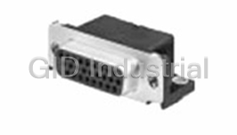
TE CONNECTIVITY 171822-4

Description
TE Connectivity 171822-4 Connector. EI Series Economy Interconnection Connectors | 4 Position | 2.5MM HOUSING
Part Number
171822-4
Price
Request Quote
Manufacturer
TE CONNECTIVITY
Lead Time
Request Quote
Category
PRODUCTS - 1
Specifications
Body Orientation
Straight
Gender
RCP
Number of Contacts
4
Number of Rows
1
Pitch
2.5 mm
Type
Housing
Features
- 2.50 mm Centerline
- 4 Positions
- Connector Style - Receptacle
Datasheet

Extracted Text
Product Specification 108-5118 製品規格 02JUL08 Rev. K AMP E.I. シリーズ・コネクタ (AMP “EI” Series, Connector) 1. 概要 1. General Descriptions: 本コネクタは一列の配列で極間は 2.5mm ピッチで構成さ This connector has been designed in single line れている。タイプは電線対基板の垂直型と水平型及び電 contact disposition in 2.5mm center line spacing. The 線対電線のパネル取付型とフリーハンギング型がある。 connectors of vertical and horizontal types for wire-to-board termination, and panel mounting and free hanging types for wire-to-wire termination, are available. 2. 適用範囲 2. Scope: 本規格は、マスターミネーションタイプを除くE.I.シリーズ・コ The products of “EI” series connectors, excepting ネクタの全ての製品について適用する。 mass termination type are governed under this specification. 3. 材料及び表面処理 3. Material and Finish: 3.1 コンタクト圧着タイプ 3.1 Contact, Crimp Type: (1) 錫めっき製品 (1) Tin-Plated Products: 材質: 黄銅及び燐青銅 Materials: Brass and Phosphor Bronze 表面処理: 錫めっき済 0.8μm以上 Finish: Pretinned, 0.8μm minimum thick (2) 金めっき製品 (2) Gold-Plated Products: 材質: 燐青銅 Materials: Phosphor Bronze 表面処理: ニッケル下地めっき 1~2μmの上に接触 Finish: 0.38 μ m minimum thick gold-plated for 部のみ金めっき 0.38μm以上 contact area only, over 1.0 ~ 2.0μm minimum thick nickel underplate 3.2 ポスト 3.2 Post: (1) 錫めっき製品(垂直タイプ及び水平タイプ) (1) Tin-Plated Products: (Vertical and Horizontal Types) 材質: 黄銅線 Materials: Brass Wire 表面処理: 銅下地めっき 0.5μm 以上の上に錫めっき 0.8μm 以上 Finish: 0.8 μm minimum thick tin-plated over 0.5 μm minimum thick copper underplate (2) 金めっき製品(垂直タイプ) (2) Gold-Plated Products: (Vertical Type) 材質: 黄銅線 Materials: Brass Wire 表面処理: ニッケル下地めっき 1~2μmの上に 金めっき 0.38μm以上 Finish: 0.38μm minimum thick gold-plated over 1.0 ~ 2.0μm thick nickel underplate タイコ エレクトロニクス アンプ株式会社 (〒213-8535 川崎市高津区久本 3-5-8) 1 of 16 Tyco Electronics AMP K.K. (3-5-8 Hisamoto Takatsu-ku Kawasaki, 213-8535) © Copyright 2007 Tyco Electronics AMP K.K. All international rights reserved. * : 商標 Trademark Product Specification 108-5118 3.3 ハウジング 3.3 Housing: (1) 材質: 6 6 ナイロン (1) Material: 6/6 NYLON (2) 難燃性: UL94V-0 (2) Flame Retardancy: UL94V-0 4. 性能 4. Performance: 4.1 定格 4.1 Rating: (1) 電圧: AC250V及びDC350V (1) Voltage: 250V AC and 350V DC (2) 電流: 2A(図1参照) (2) Current: 2A (Refer to Fig.1) (3) 周囲温度: 図1参照 (3) Temperature: Refer to Fig. 1 4.2 一般性能 4.2 Performance Requirements: 表1に示す一般性能に全て合格しなければならない。 When tested in accordance with the applicable test method, all the products shall show performance capability to be acceptable to the following requirements. Rev. K 2 of 16 Product Specification 108-5118 試験方法 項番 試験項目 規 格 値 項番 Test Method Paragraph Test Items Specified Requirements Para. No. 4.2.1 6.1 ローレベル抵抗 10mΩ以下 Termination Resistance Low level termination resistance shall be 10 mΩ Max. 4.2.2 6.2 絶縁抵抗 500MΩ以上(DC500V において) Insulation Resistance Insulation Resistance shall be 500M Ω Min. when measured at 500V DC. 4.2.3 6.3 耐電圧 AC750V、1 分間で異常なきこと。 Dielectric Strength Connector shall show no abnormalities after applying test potential of 750V AC for 1 minute. 4.2.4 6.4 温度上昇 30℃以下(注・図1参照) Temperature Rising Temperature rising of connector shall be 30 deg. Max. (Refer to Fig. 1) 4.2.5 6.5 コンタクト保持力 黄銅コンタクト りん青銅コンタクト 19.6N(2kgf)以上/1極 24.5N(2.5kgf)以上/1極 Contact Retention Force Brass Contact Phosphor Bronze Contact 19.6N (2kgf) Min. 24.5N (2.5kgf) Min. (4.41 lbs.) (5.51 lbs.) per position per position 4.2.6 6.6 低周波振動 振動中 1μ秒を超える不連続導通を生じないこと。 ローレベル抵抗: 錫めっき製品 20mΩ以下 金めっき製品 18mΩ以下 Vibration(Low Frequency) No electrical discontinuity greater than 1 microsecond shall occur during the test. Termination Tin-Plated Products 20mΩ Max. Resistance: (Low level) Gold-Plated Products 18mΩ Max. 表1 (続く) Table 1 (Cont.) Rev. K 3 of 16 Product Specification 108-5118 試験方法 項番 試験項目 規 格 値 項番 Test Method Paragraph Test Items Specified Requirements Para. No. 4.2.7 耐湿性(定常状態) 割れ、フクレ、その他機能を損う欠陥のないこと。 6.7 ローレベル抵抗: 錫めっき製品 20mΩ以下 金めっき製品 18mΩ以下 Humidity No abnormalities such as cracks, blister and other defects (Steady State) that are detrimental to connector functions, shall be present. Termination Tin-Plated Products 20mΩ Max. Resistance: Gold-Plated Products 18mΩ Max. (Low Level) 4.2.8 塩水噴霧 割れ、フクレ、その他機能を損う欠陥のないこと。 6.8 ローレベル抵抗: 錫めっき製品 20mΩ以下 金めっき製品 18mΩ以下 Salt Spray No abnormalities such as cracks, blister and other defects that are detrimental to connector functions, shall be present. Termination Tin-Plated Products 20mΩ Max. Resistance: Gold-Plated Products 18mΩ Max. (Low Level) 4.2.9 6.9 はんだ付性 半田ヌレは 95%以上 (ポストヘッダーのみに適 用) Solderability More than 95% of the tested area shall appear with (Applicable to sufficient coverage of wet solder. post header only) 4.2.10 6.10 はんだ耐熱性 機能を損う変形、欠陥のないこと。 (ポストヘッダーのみに適 用) Soldering Heat Connector shall be free from the deformation and defects Resistivity that are detrimental to connector functions. (Applicable to post header only) 2 4.2.11 6.11 圧着部引張強度 AWG#20(0.52mm ) 68.6N(7kgf)以上 2 AWG#22(0.3mm ) 49.0N(5kgf)以上 2 AWG#24(0.2mm ) 29.4N(3kgf)以上 2 AWG#26(0.13mm ) 19.6N(2kgf)以上 2 AWG#28(0.08mm ) 12.7N(1.3kgf)以上 2 AWG#30(0.05mm ) 7.8N(0.8kgf)以上 Crimp Tensile Strength Wire Size Tensile Strength (Min.) 2 mm (AWG) N (kgf) (lbs.) 0.52 (#20) 68.6N (7kgf) (15.43) 0.3 (#22) 49.0N (5kgf) (11.02) 0.2 (#24) 29.4N (3kgf) (6.61) 0.13 (#26) 19.6N (2kgf) (4.41) 0.08 (#28) 12.7N (1.3kgf) (2.87) 0.05 (#30) 7.8N (0.8kgf) (1.76) 表1 (続く) Table 1 (Cont.) Rev. K 4 of 16 Product Specification 108-5118 試験方法項 項番 試験項目 規 格 値 番 Test Method Paragraph Test Items Specified Requirements Para. No. 4.2.12 6.12 ポスト保持力(ポストヘッダ 19.6N(2kgf)以上 ーのみに適用) Post Retention Force Retention force shall be 19.6N (2kgf) Min. (4.41 lbs.) 4.2.13 6.13 コンタクト単体挿抜力 挿入力 引抜力 初回 5.9N(0.6kgf)以下 0.98N(0.1kgf)以上 10 回目 5.9N(0.6kgf)以下 0.78N(0.08kgf)以上 Contact Insertion and Contact insertion/extraction force shall be conforming to Extraction Force: the value specified below. Insertion Extraction Initial 5.9N (0.6kgf) Max. 0.98N (0.1kgf) Min. th 10 Cycle 5.9N (0.6kgf) Max. 0.78N (0.08kgf) Min. 表1 (続く) Table 1 (Cont.) Rev. K 5 of 16 Product Specification 108-5118 試験方法 項番 試験項目 規 格 値 項番 Test Paragraph Test Items Specified Requirements Method Para. No. 4.2.14 コ ネ ク タ 挿 抜 挿入力 引抜力 6.14 力 12 極 初回 73.5N (7.5kgf)以下 19.6N (2.0kgf)以上 10 回目 73.5N (7.5kgf)以下 14.7N (1.5kgf)以上 10 極 初回 68.6N (7.0kgf)以下 19.6N (2.0kgf)以上 10 回目 68.6N (7.0kgf)以下 14.7N (1.5kgf)以上 9 極 初回 68.6N (7.0kgf)以下 19.6N (2.0kgf)以上 10 回目 68.6N (7.0kgf)以下 14.7N (1.5kgf)以上 8 極 初回 63.7N (6.5kgf)以下 14.7N (1.5kgf)以上 10 回目 63.7N (6.5kgf)以下 9.8N (1.0kgf)以上 7 極 初回 53.9N (5.5kgf)以下 14.7N (1.5kgf)以上 10 回目 53.9N (5.5kgf)以下 9.8N (1.0kgf)以上 6 極 初回 49.0N (5.0kgf)以下 14.7N (1.5kgf)以上 10 回目 49.0N (5.0kgf)以下 9.8N (1.0kgf)以上 5 極 初回 39.2N (4.0kgf)以下 14.7N (1.5kgf)以上 10 回目 39.2N (4.0kgf)以下 9.8N (1.0kgf)以上 4 極 初回 29.4N (3.0kgf)以下 9.8N (1.0kgf)以上 10 回目 29.4N (3.0kgf)以下 7.8N (0.8kgf)以上 3 極 初回 24.5N (2.5kgf)以下 7.8N (0.8kgf)以上 10 回目 24.5N (2.5kgf)以下 4.9N (0.5kgf)以上 2 極 初回 19.6N (2.0kgf)以下 7.8N (0.8kgf)以上 10 回目 19.6N (2.0kgf)以下 4.9N (0.5kgf)以上 Connector No. of Insertion Force (Max.) Extraction Force (Min.) Meas- Insertion and Posi- ured at Extraction tions N (kgf) (lbs.) N (kgf) (lbs.) Force 12 Initial 73.5N (7.5kgf) (16.5) 19.6N (2.0kgf) (4.4) th 10 73.5N (7.5kgf) (16.5) 14.7N (1.5kgf) (3.3) 10 Initial 68.6N (7.0kgf) (15.4) 19.6N (2.0kgf) (4.4) th 10 68.6N (7.0kgf) (15.4) 14.7N (1.5kgf) (3.3) 9 Initial 68.6N (7.0kgf) (15.4) 19.6N (2.0kgf) (4.4) th 10 68.6N (7.0kgf) (15.4) 14.7N (1.5kgf) (3.3) 8 Initial 63.7N (6.5kgf) (14.3) 14.7N (1.5kgf) (3.3) th 10 63.7N (6.5kgf) (14.3) 9.8N (1.0kgf) (2.2) 7 Initial 53.9N (5.5kgf) (12.1) 14.7N (1.5kgf) (3.3) th 10 53.9N (5.5kgf) (12.1) 9.8N (1.0kgf) (2.2) 6 Initial 49.0N (5.0kgf) (11.0) 14.7N (1.5kgf) (3.3) th 10 49.0N (5.0kgf) (11.0) 9.8N (1.0kgf) (2.2) 5 Initial 39.2N (4.0kgf) (8.8) 14.7N (1.5kgf) (3.3) th 10 39.2N (4.0kgf) (8.8) 9.8N (1.0kgf) (2.2) 4 Initial 29.4N (3.0kgf) (6.6) 9.8N (1.0kgf) (2.2) th 10 29.4N (3.0kgf) (6.6) 7.8N (0.8kgf) (1.8) 3 Initial 24.5N (2.5kgf) (5.5) 7.8N (0.8kgf) (1.8) th 10 24.5N (2.5kgf) (5.5) 4.9N (0.5kgf) (1.1) 2 Initial 19.6N (2.0kgf) (4.4) 7.8N (0.8kgf) (1.8) th 10 19.6N (2.0kgf) (4.4) 4.9N (0.5kgf) (1.1) 表1 (続く) Table 1 (Cont.) Rev. K 6 of 16 Product Specification 108-5118 試験方法 項番 試験項目 規 格 値 項番 Test Method Paragraph Test Items Specified Requirements Para. No. 4.2.15 6.15 パネル挿入力・保持力 パネル挿入力 7,8 極 78.4N (8kgf)以下 (パネル取付型のみに適 2~6 極 49.0N (5kgf)以下 用) パネル保持力 7,8 極 98.1N (10kgf)以上 2~6 極 73.5N (7.5kgf)以上 Panel Insertion and Panel Insertion 7 & 8 Pos. 78.4N (8kgf) Max. Retention Force Force 2~6 Pos. 49.0N (5kgf) Max. (Applicable to panel Panel Retention 7 & 8 Pos. 98.1N (10kgf) Min. mount type connector) Force 2~6 Pos. 73.5N (7.5kgf) Min. 表1 (終り) Table 1 (End) 5. 品質保証条件 5. Quality Assurance Provisions: 5.1 Test Specimens: 5.1 試料 Test specimens shall be prepared in accordance 試料は完全に管理された製品を使用すること。 with the methods and procedure specified by appropriate AMP specification and instruction sheet, by using applicable application tooling. 5.2 試験環境 5.2 Test Conditions: 下記に示す環境条件のもとで試験を行うこと。 All the tests shall be conducted under any combination of the following test conditions. 温度 15℃~35℃ Temperature: 15°C ~ 35°C 湿度 45%~75% Relative Humidity: 45% ~ 75% 4 5 気圧(水銀柱) 8.7×10 ~1.07×10 Pa 4 5 Atmospheric Pressure: 8.7X10 ~ 1.07X10 Pa (650~800mmHg) (650~800mmHg) Rev. K 7 of 16 Product Specification 108-5118 図1 電流対温度上昇特性 Fig. 1 Temperature vs. Current The maximum current that can be carried in any given 本製品の最大許容温度は、ハウジングの最大許容温度、 connector is limited by maximum operating 錫めっき・コンタクトの最大許容温度により、-20℃~+ temperature of housing material used and influenced 95℃の範囲とし、使用電流によるコンタクト部分の温度上 by the wire size, connector size (number of cavities operating) and the ambient temperature in which the 昇分と使用環境による周囲温度の和により次式から算出 connector is used. The maximum intensity of current される。 can be calculated by the following formula, taking consideration of temperature rating specified in the 最大許容温度=温度上昇+周囲温度 range of -20°C through +95°C (-13.0°F through +203°F) and maximum allowable temperature for この時の温度上昇は、個々の電線の許容電流値以下と tin-plated connector. し、電線サイズと種類及び電流値により図1より選ぶこと。 Maximum Operating Temperature = 但し、電流値は温度上昇が30℃以下の範囲内とする。 Temperature Rise + Ambient Temperature The rate of temperature rising must be held within the limit obtained from maximum allowable current loaded on individual operating wire and total current shall be determined by the curves shown in Fig.1. In any case, total amount of temperature rising shall be held within 30 degrees over the ambient temperature. Note: The dotted line section indicates estimated rate of temperature rising. Rev. K 8 of 16 Product Specification 108-5118 6. Test Methods: 6. 試験方法 6.1 Termination Resistance (Low Level): 6.1 ローレベル抵抗試験方法 Low level termination resistance is obtained by 図2に示す如く、回路電流 50mA 以下、回路開放電圧 measuring millivolt drop of the test circuit as shown 50mV 以下の測定回路において測定し、電線導体抵抗 in Fig.2, by applying test current of 50 mA at open 75mm 分を差し引いて算出する。 circuit voltage of 50mV flowing through the circuit. From the measured value, low level resistance is calculated after deducting resistance of crimped wire of 75mm in length. 6.2 絶縁抵抗試験方法 6.2 Insulation Resistance: コネクタを嵌合状態(ポストヘッダーは基板に取付けない Insulation resistance is obtained by applying test で)にし、ハウジング内の隣接している端子相互間を potential of 500V DC across the adjacent contacts DC500Vで測定する。 in the connector housing after connector is mated without having post header mounted on printed circuit board. 6.3 耐電圧試験方法 6.3 Dielectric Strength: コネクタを嵌合状態(ポストヘッダーは基板に取付けない Dielectric strength is measured by applying test で)にし、ハウジング内の隣接している端子相互間に potential of 750V AC across the adjacent contacts in AC750V、1分間印加する。 the connector housing after connector is mated without having post header mounted on printed circuit board. 6.4 温度上昇試験方法 6.4 Temperature Rising: 試料を直列になるように結線し、測定ヵ所はコンタクト圧 After having contacts series wired, measure 着部分を熱電対法にて測定する。 temperature rising of contacts by probing on wire crimp by using thermocouple. 6.5 コンタクト保持力試験方法 6.5 Contact Retention Force: ハウジングをショッパー引張試験機に取り付け、ハウジ Contact loaded housing must be fastened on the ングに挿着されたコンタクトを軸方向に毎分 100mm の速 head of tensile testing machine, and apply an axial 度で操作して測定する。 pull off load to contact lead by operating the head to travel with the speed at a rate of 100mm a minute. Contact retention force is determined when receptacle contact is dislodged from housing cavity. Rev. K 9 of 16 Product Specification 108-5118 6.6 低周波振動試験方法 6.6 Vibration: 嵌合状態の試料をプリント基板又は取付用パネルに固 Contact loaded and mated pair of connectors must 定し、直列回路になるように結線し、試験機に取り付け、 be mounted on printed circuit board or mounting 0.1Aを通電して試験する。 panel with all the contacts series wired, and 振動方向はX、Y、Z方向各2時間、最大全振幅1.5mm、 fastened on the vibration table. The said connectors 振動周波数10~55Hz往復1分間。(尚、電線対電線接続 are vibrated with maximum amplitude of 1.5mm タイプはパネル取付型によって試験を代表する) both sides in the sweeping frequencies to reciprocate between 10 and 55 Hz, changing at a rate of one cycle a minute. During the vibration, the circuit must be monitored by applying to the current of 0.1A for occurrence of electrical discontinuity resulted from the vibration. Vibration must be applied to the sample connector in three axial planes for totally 6 hours, each plane vibrated for 2 hours. 6.7 耐湿度試験方法 6.7 Humidity: 嵌合状態の試料を湿度90~95%、温度40℃の環境中で Humidity testing shall be performed by exposing the 連続96時間放置後、室温中に1時間放置してから測定 contact-loaded and mated pair of connectors under する。 the atmosphere of 90 ~ 95% R.H. at 40°C for 96 hours in the test chamber, and after the test duration, recondition in the room temperature for 1 hour before undergoing the subsequent measurements. 6.8 塩水噴霧試験方法 6.8 Salt Spray: 嵌合状態の試料を、塩水濃度5%、温度35℃の環境中 Contact-loaded and mated pair of connectors shall で連続48時間放置後、室温中に1時間放置してから測 be exposed under the 5% salt solution spray for 48 定する。 hours at 35°C. After completion of test duration, the sample connectors shall be taken out from the test chamber and reconditioned in the room temperature for 1 hour, and tested for low level termination resistance. 6.9 はんだ付試験方法(電線対基板タイプのポストヘッ 6.9 Solderability (Applicable to Post Header, ダーに適用) Wire-to-Board Only): ポストヘッダーのはんだ付け部分をフラックス(アルファ Dip contact ends of post header in flux (ALPHA 100 100、GX-5、GX-7)に5~10秒間浸漬した後230±5℃の GX-5 or GX-7 is recommended.) for 5~10 seconds, はんだ(錫60%、鉛40%)槽中に3±0.5秒間浸漬する。 then, immerse in soldering tub that is filled with 60% tin, 40% lead solder heated at 230±5°C, for 3±0.5 seconds. Rev. K 10 of 16 Product Specification 108-5118 6.10 はんだ耐熱試験方法(電線対基板タイプのポストヘッ 6.10 Soldering Heat Resistivity (Applicable to Post ダーに適用) Header, Wire-to-Board Type Only): With post header inserted into the mounting holes, ポストヘッダーをプリント基板の取付穴に挿入後260± printed circuit board shall be processed for soldering 5℃のはんだ槽中に10±0.5秒間浸漬する。手半田の場 for 10±0.5 seconds in the soldering tub where the 合ポストヘッダーをプリント基板の取付穴に挿入後350 temperature is controlled at 260±5°C. (Manual Soldering) ±10℃ 1~2秒にて半田付を行う。但しポストの半田付 In case of manual soldering, test the sample post 部にこて先等による加圧のなきこと。 header assembled on PCB, by applying soldering iron, controlled at 350±10°C for 1 to 2 seconds. In this testing, soldering spot of the post shall remain free from the pressure by the applied soldering iron. 6.11 圧着部引張試験方法 6.11 Crimp Tensile Strength: 電線(撚線)を圧着したコンタクトをショッパー引張試験 Fasten a wire-crimped contact lead onto the head of 機に取り付け、軸方向に毎分100mmの速度で操作して tensile testing machine and apply an axial pull off 測定する(被覆部は含まない)。 load to the wire by operating the head to travel with the speed at a rate of 100mm a minute without insulation support crimp set in effect. Crimp tensile strength is determined when the wire is broken or is pulled off from the wire crimp. 6.12 ポスト保持力試験方法(電線対基板タイプのポストヘ 6.12 Post Retention Force (Applicable to Post Header, ッダーに適用) Wire-to-Board Type Only): ポストヘッダー・アッセンブリーのハウジングを図3の如く Place post inserted header assembly over the test 治具で受け、ポスト先端を軸方向に垂直にフォース・ゲ fixture in the manner as shown in Fig.3, and apply ージで押して測定する。 an axial push down force on top of post contact. Post retention force is determined when the post is dislodged from the inserted position. Measurement shall be done by using a force gage. 6.13 コンタクト挿抜力試験方法 6.13 Contact Insertion/Extraction Force: リセプタクル・コンタクトを引張試験機に取り付け、図4に Fasten a receptacle contact on the head of tensile 規定するゲージを軸方向に毎分100mmの速度で操作 testing machine, and apply axial loads to the し、測定する。 receptacle contact to mate with and unmate from the gage, specified in Fig.4, by operating the head to travel with the speed at a rate of 100mm a minute. Rev. K 11 of 16 Product Specification 108-5118 6.14 コネクタ挿抜力試験方法 6.14 Connector Mating/Unmating Force: Fasten receptacle contacts loaded housing on tensile コネクタを引張試験機に取り付け、軸方向に毎分100mm testing machine in the manner that they are aligned to の速度で操作して嵌合、離脱を行いコネクタの挿入力及 mate with and unmate from the gage as the head is び引抜力を測定する。 operated to travel with the speed at a rate of 100mm a minute. 6.15 パネル挿入力・保持力試験方法(電線対電線タイプパ 6.15 Panel Insertion and Retention Force (Applicable to ネル取付型キャップハウジングに適用) Post Header, Wire-to-Board Type Only): キャップハウジングを引張試験機に取り付け、軸方向に Fasten cap housing onto the head of tensile testing 毎分100mmの速度で操作して製品図面上に指定された machine, and test the force required to insert the 寸法で穴明けが施された取付用パネルへの挿入力及び housing into the mounting hole that is made through 装着後の保持力を測定する。 the mounting panel, and the force required to pull-off the housing from the panel, by operating the head to travel with the speed at a rate of 100mm a minute. Rev. K 12 of 16 Product Specification 108-5118 7. 試験順序 7. Test Sequence: 試験は各試料をグループ別に分け、表2の順序で実施す The following sample groups shall be prepared, and ること。 employed for the tests in the sequence specified in Table 2 below. 試験方法 試験項目 試験グループ番号 Test Sample Group Test Item Method 1 2 3 4 5 6 7 8 9 10 11 12 Paragraph ローレベル抵抗 6.1 1,3 1,3 1.3 Termination Resistance (Low Level) 絶縁抵抗 6.2 1 Insulation Resistance 耐電圧 6.3 2 Dielectric Strength 温度上昇 6.4 1 Temperature Rising コンタクト保持力 6.5 3 Contact Retention Force 低周波振動 6.6 2 Vibration (Low Frequency) 耐湿性 6.7 2 Humidity 塩水噴霧 6.8 2 Salt Spray はんだ付性 6.9 1 Solderability はんだ耐熱性 6.10 1 Soldering Heat Resistibility 圧着部引張強度 6.11 1 Crimp Tensile Strength ポスト保持力 6.12 1 Post Retention Force コンタクト単体挿抜力 6.13 1 Contact Insertion / Extraction Force コネクタ挿抜力 6.14 1 Connector Mating / Unmating Force パネル挿入力・保持力 6.15 1 Panel Insertion and Retention Force 表2 Table 2 Rev. K 13 of 16 Product Specification 108-5118 図2 ローレベル抵抗試験方法 Fig. 2 Low Level Termination Resistance Measuring Method Rev. K 14 of 16 Product Specification 108-5118 図3 ポスト保持力試験方法 Fig. 3 Post Retention Force Measuring Method 図4 コンタクト挿抜力測定用ゲージ Fig. 4 Contact Insertion/Extraction Force Measuring Method Rev. K 15 of 16 Product Specification 108-5118 作成 Y.NAKAMURA 11/MAR/87 (Prepared by) Name Date 検閲 J.TANIGAWA 11/MAR/87 (Checked by) Name Date 承認 N.ONOUE 12/MAR/87 (Approved by) Name Date 改訂 改訂記録 作成 照査 承認 EC DATE LTR REVISION RECORD DR CHK APP 再作成(Re-create in K T.T K.Y T.F 02JUL08 MS-Word format.) Rev. K 16 of 16
Frequently asked questions
What makes Elite.Parts unique?

What kind of warranty will the 171822-4 have?
Which carriers does Elite.Parts work with?
Will Elite.Parts sell to me even though I live outside the USA?
I have a preferred payment method. Will Elite.Parts accept it?
Why buy from GID?

Quality
We are industry veterans who take pride in our work

Protection
Avoid the dangers of risky trading in the gray market

Access
Our network of suppliers is ready and at your disposal

Savings
Maintain legacy systems to prevent costly downtime

Speed
Time is of the essence, and we are respectful of yours
Related Products

Te Connectivity 1-175102-1 CONN CONTACT 22-26AWG TIN CRIMP
TE Connectivity 1734078-4 Standard Board Mount Connector
TE Connectivity 1735446-4 Connector. HPI | 2.0mm Pitch | Locking type | Vertical with latch
TE Connectivity 175778-3 CONN RECEPT 3POS 2MM CRIMP
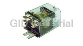
TE Connectivity 188 Series 30 Amp Power Relays
TE Connectivity 188-24C200 Relay - R3464 INDUSTRIAL RELAY
Request a Quote

The quote request has been received
Close

Facing challenges or have inquiries? Feel free to contact us!
Call Us +1-469-283-2440
What they say about us
FANTASTIC RESOURCE
One of our top priorities is maintaining our business with precision, and we are constantly looking for affiliates that can help us achieve our goal. With the aid of GID Industrial, our obsolete product management has never been more efficient. They have been a great resource to our company, and have quickly become a go-to supplier on our list!
Bucher Emhart Glass
EXCELLENT SERVICE
With our strict fundamentals and high expectations, we were surprised when we came across GID Industrial and their competitive pricing. When we approached them with our issue, they were incredibly confident in being able to provide us with a seamless solution at the best price for us. GID Industrial quickly understood our needs and provided us with excellent service, as well as fully tested product to ensure what we received would be the right fit for our company.
Fuji
HARD TO FIND A BETTER PROVIDER
Our company provides services to aid in the manufacture of technological products, such as semiconductors and flat panel displays, and often searching for distributors of obsolete product we require can waste time and money. Finding GID Industrial proved to be a great asset to our company, with cost effective solutions and superior knowledge on all of their materials, it’d be hard to find a better provider of obsolete or hard to find products.
Applied Materials
CONSISTENTLY DELIVERS QUALITY SOLUTIONS
Over the years, the equipment used in our company becomes discontinued, but they’re still of great use to us and our customers. Once these products are no longer available through the manufacturer, finding a reliable, quick supplier is a necessity, and luckily for us, GID Industrial has provided the most trustworthy, quality solutions to our obsolete component needs.
Nidec Vamco
TERRIFIC RESOURCE
This company has been a terrific help to us (I work for Trican Well Service) in sourcing the Micron Ram Memory we needed for our Siemens computers. Great service! And great pricing! I know when the product is shipping and when it will arrive, all the way through the ordering process.
Trican Well Service
GO TO SOURCE
When I can't find an obsolete part, I first call GID and they'll come up with my parts every time. Great customer service and follow up as well. Scott emails me from time to time to touch base and see if we're having trouble finding something.....which is often with our 25 yr old equipment.
ConAgra Foods