

 Manufacturers
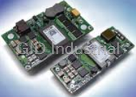
TDK MRW170
Description
TCK MRW170 Power Supply. 65W | AC Input 100-240V, 50-60Hz
Part Number
MRW170
Price
Request Quote
Manufacturer
TDK
Lead Time
Request Quote
Category
TBD
Specifications
Flash with Security
32KB
Interface
UART
Power, Apparent Power, and Power Factor
Accumulated Watt-Hours, Kilowatt-Hours
RoHS
Compliant
Features
- 22-Bit Delta-Sigma ADC with Independent 32-Bit Compute Engine (CE)
- 32KB Flash with Security
- 32kHz Time Base with Hardware Watchdog Timer
- 46-64Hz Line Frequency Range with Same Calibration
- 8-Bit MPU (80515), One Clock Cycle per Instruction with 2KB MPU XRAM
- Accumulated Watt-Hours, Kilowatt-Hours
- Complete Application Firmware Provides:
- Digital Temperature Compensation
- Four Sensor Inputs—V3P3A Referenced
- Integrated In-Circuit Emulator (ICE) Interface for MPU Debug
- Intelligent Switch Control at Zero Crossings
- Packaged in a RoHS-Compliant (6/6) Lead(Pb)-Free, 32-Pin QFN (5mm x5mm)
- Phase Compensation (±15°)
- Quick Calibration Routines
- True RMS Calculations for Current, Voltage, Line Frequency, Real Power, Reactive Power, Apparent Power, and Power Factor
- UART Interface and Up to 10 General-Purpose 5V Tolerant I/O Pins
- Voltage Reference
Datasheet

Extracted Text
A111_MRW (1/19) TDK Switching Power Supply Wide-input 2- and 3-output type bestseller power supply M SERIES MRW UL/CSA/TÜV approved [FEATURES] • Wide-input (AC.100V/200V switching not required) thin-type multi-output power supply. • Open frame type. • POK signal function (MRW-150/-151/-160/-161). • Low noise (FCC class B). [SUMMARY] The M series MRW products are open-frame multi-output power supplies characterized by the wide input range and thin type. They are available at low prices and Safety standards certified with full EMC countermeasures. It is recommended to use them as economical export power supplies. In addition to the conventional products, the 170 series and 350 series are supported newly. PART NUMBERS AND RATINGS Maximum output Output1[V1] Output2[V2] Output3[V3] Part No. power*(W) Voltage(V) Current(A) Voltage(V) Current(A) Voltage(V) Current(A) MRW-135 28 +5 0.5 to 2 +12 0.3 to 1.5(2.5, 3s) MRW-150 35 +5 1 to 2.2(Max.4) +12 0.6 to 1.8(Max.2.5) –12 0 to 0.1(Max.0.3) MRW-151 35 +5 1 to 2.2(Max.4) +15 0.5 to 1.4(Max.2) –15 0 to 0.1(Max.0.25) MRW-160 50 +5 1 to 5(Max.6) +12 0.6 to 2(Max.2.5) –12 0 to 0.1(Max.0.5) MRW-161 50 +5 1 to 5(Max.6) +15 0.5 to 1.5(Max.2) –15 0 to 0.1(Max.0.4) MRW-170 65 +5 0.8 to 5(Max.7) +12 0.3 to 1.7(Max.2.5) –12 0.3 to 1.7(Max.2.5) MRW-171 65 +5 0.8 to 5(Max.7) +15.8 0.3 to 1.3(Max.2) –15.8 0.3 to 1.3(Max.2) MRW-350 40 +5 0.5 to 3 +12 0.3 to 2 –12 0 to 0.1 *The total sum of the output voltage multiplied by the output current cannot exceed the maximum output power. For the details, please refer to the next pages. • :Stock products. All specifications are subject to change without notice. A111_MRW (2/19) TDK Switching Power Supply M SERIES MRW-135 UL/CSA/TÜV approved SPECIFICATIONS AND STANDARDS PART NO. MRW-135 Rated output voltage V1 +5V • 2A 1 4 and current*V2 +12V • 1.5A(Peak 2.5A, 3s max.)* Maximum output power W 28 INPUT CONDITIONS Input voltage Eac V 90 to 264[Rating: 100 to 120/200 to 240] Input frequency Hz 47 to 66[Rating: 50 to 60](Single phase) Input current A 0.8max./0.5max.[AC.100 to 120/200 to 240V] Fuse rating A 2[Built-in] Surge current A 50max./100max.[AC.100 to 120/200 to 240V, 25°C, cold start] Leakage current mA 0.5max./0.75max.[AC.100 to 120/200 to 240V] Efficiency % 73typ.[AC.100 to 120V] OUTPUT CHARACTERISTICS Output voltage Edc V +5(V1) +12(V2) Voltage variable range % +5, –3 V2 varies simultaneously and in the same direction as V1. 4 Maximum output current A 2 1.5(Peak 2.5A, 3s)* 3 Minimum output current*A 0.5 0.3 Output setting [Voltage] V 5±0.02 — conditions [Current] A 2 1.5 Input variation % 1max. 1.5max.[AC.90 to 132V/180 to 264V] 2 Load variation*% 2max. 3max. Temperature variation Voltage % 2max. 3max. [0 to +50°C] stability Total variation % +4, –3max. ±5max. Drift % 0.5max.[25°C, input and output ratings, after input voltage ON for 30min to 8h] Dynamic load %/ms ±4max./1max.[50 to 100% sudden load change] Ripple Ep-p mV 80max. 120max. Ripple noise Ep-p mV 150max. 290max. Start up time ms 750typ. Hold up time ms 10min.(15typ.)[AC.100V input], 20min.(25typ.)[AC.120V input] AUXILIARY FUNCTIONS Indicator display No Overvoltage protection Only 5V built-in protection, voltage shut-down type(overvoltage threshold 5.8 to 6.9V), recovers upon reset. Overcurrent protection 41W min., total power type Remote ON-OFF No Remote sensing No Current balance No Output voltage external variable function No STANDARDS Safety standards UL1950-3, CSA950-95(C-UL), EN60950(TÜV) approved. Noise terminal voltage FCC class B, VDE0871 class B compliant. CONSTRUCTIONS External dimensions mm 35·80·120[H·W·L] Weight g 300max. Mounting method Can be attached to 1 side. Case and cover — Input and output cables Sold separately(Part No.: 4EU20B241) *1 Current rating(maximum output current) is determined for 0 to +50°C. Derating is required when used outside this temperature range. *2 Load variation only for an output to be measured with other outputs fixed to V1 at 1.5A and V2 at 1.5A. *3 The output voltages V1 and V2 may not output regular voltages at the minimum output current or lower. *4 If +12V load current exceeds 1.5A, the time should be limited to 3 sec or shorter with the effective current maintained at 1.5A or lower for use. All specifications are subject to change without notice. A111_MRW (3/19) TDK Switching Power Supply M SERIES MRW-135 UL/CSA/TÜV approved Dimensions in mm SHAPES AND DIMENSIONS ±1mm : without specified dimensions MRW-135 120 4 112–0.7 31max. 1.6–0.2 Primary Secondary P1 P2 P3 P4 CP52 P5 P6 P7 P8 –P1 P2 CP51 P3 P4 L CP2 N CP1 (9) 3max. 4-ş3.5 [Terminal place] Output FG: CP1 CP51 CP52 Input: CP2 P1 +12V COMMON L LIVE P2 COMMON N NEUTRAL P3 +5V +5V P4 COMMON P5 — COMMON P6 — P7 — +12V P8 — • Use M3.5 installation screw holes and solder-land must not over than 9mm from edge of printed circuit board. Components surface must keep less than 6.5mm diameter from the hole center. (When use metal cover or other metal installation parts, please keep more than 4mm from primary components and any lead wires for safety.) All specifications are subject to change without notice. 80 72 0.7 4 (9) A111_MRW (4/19) TDK Switching Power Supply M SERIES MRW-150/151 UL/CSA/TÜV approved SPECIFICATIONS AND STANDARDS PART NO. MRW-150 MRW-151 4 4 V1 +5V • 2.2A(4A)*+5V • 2.2A(4A)* Rated output voltage 4 4 V2 +12V • 1.8A(2.5A)*+15V • 1.4A(2A)* 1 and current* 4 4 V3 –12V • 0.1A(0.3A)*–15V • 0.1A(0.25A)* Maximum output power W 35 35 INPUT CONDITIONS Input voltage Eac V 90 to 264[Rating: 100, 120, 200, 240] Input frequency Hz 47 to 66[Rating: 50 to 60](Single phase) Input current A 1max./0.5max.[AC.100/200V, maximum output rated power] Fuse rating A 2.5[Built-in] Surge current A 50max./100max.[AC.100/200V, 25°C, cold start] Leakage current mA 0.5max./0.75max.[AC.100/200V, 25°C, output rating] Efficiency % 70typ. 70typ. OUTPUT CHARACTERISTICS Output voltage Edc V +5(V1) +12(V2) –12(V3) +5(V1) +15(V2) –15(V3) V2 varies simultaneously and V2 varies simultaneously and Voltage variable range % +5, –3 +5, –3 in the same direction as V1. in the same direction as V1. 1 Maximum output current*A 4 2.5 0.3 4 2 0.25 Rated output current A 2.2 1.8 0.1 2.2 1.4 0.1 2 Minimum output current*A 1 0.6 0 1 0.5 0 Output setting [Voltage] V 5±0.02 — — 5±0.02 — — conditions [Current] A 2.2 1.8 0.1 2.2 1.4 0.1 Overvoltage threshold V 5.8 to 6.9 5.8 to 6.9 Input variation % 1typ. 1typ. 1typ. 1typ. 1typ. 1typ. 3 Load variation*% 3typ 5typ. 1typ. 3typ. 5typ. 1typ. Temperature variation Voltage % 2typ. 2typ. 1typ. 2typ. 2typ. 2typ. [0 to +50°C] stability Total variation % +4, –2max. ±5max. ±6max. +4, –2max. +3, –8max. ±6max. Drift % 0.5max.[25°C, input and output ratings, after input voltage ON for 30min to 8h] Dynamic load %/ms ±4max./2max.[50 to 100% sudden load change] Ripple Ep-p mV 50max. 80max. 30max. 80max. 120max. 30max. Ripple noise Ep-p mV 150max. 290max. 290max. 150max. 350max. 350max. Start up time ms 600max.[25°C, input and output ratings] 530max.[25°C, input and output ratings] Rise time ms 20max.[25°C, input and output ratings] 10max.[25°C, input and output ratings] Hold up time ms 15min.[25°C, input and output ratings] 15min.[25°C, input and output ratings] AUXILIARY FUNCTIONS Indicator display No Overvoltage protection Only 5V built-in protection, voltage shut-down type, recovers upon reset (interval approx. 45s). Overcurrent protection 36W min., total power type Remote ON-OFF No Remote sensing No STANDARDS Safety standards UL1950-3, CSA950-95(C-UL), EN60950(TÜV) approved. Noise terminal voltage FCC class B, VDE0871 class B compliant. CONSTRUCTIONS External dimensions mm 30·100·160[H·W·L] Weight g 350max. Mounting method 1 side(Open frame) Case and cover Frame/cover sold separately (Part No.: 2JF00B157/2JC0ZB156) Input and output cables Sold separately(Part No.: 4EU40B153) *1 Current rating(maximum output current) is determined for 0 to +50°C. Derating is required when used outside this temperature range. *2 Normal output voltages might possibly not be maintained if outputs V2, V3 fall below V1 minimum current values. *3 Load range V1: 1 to 2.2A, V2: 0.6 to 1.8A, V3: 0 to 0.1A *4 At the maximum output current value within the parentheses, the sum of all output(V1,V2 and V3) power values can not exceed this maximum output power. All specifications are subject to change without notice. A111_MRW (5/19) TDK Switching Power Supply M SERIES MRW-150/151 UL/CSA/TÜV approved Dimensions in mm SHAPES AND DIMENSIONS ±1mm : without specified dimensions MRW-150/151 ş14 Clearance(soldering side) ş14 Clearance(soldering side) 160 26max. 121.9–0.7 2max. P2 CP54 P1 P4 P3 CP53 –P2 P1 P4 P3 CP52 P2 P1 P4 P3 CP51 P2 4-ş4 P1 CP1 N CP2 L 5max. 14G Pad(soldering side) FG terminal 30max. 14 Clearance(soldering side) [Terminal place] CP1: AC INPUT CP51, CP52, CP53: OUTPUT CP54: POWER OK SIGNAL L LIVE MRW-150 MRW-151 P1 COMMON N NEUTRAL P1 +5V +5V P2 POWER OK SIGNAL CP2: FG P2 COMMON COMMON P3 +12V +15V P4 –12V –15V All specifications are subject to change without notice. 100 80 0.7 A111_MRW (6/19) TDK Switching Power Supply M SERIES MRW-160/161 UL/CSA/TÜV approved SPECIFICATIONS AND STANDARDS PART NO. MRW-160 MRW-161 3 3 V1 +5V • 5A(6A)*+5V • 5A(6A)* Rated output voltage 3 3 V2 +12V • 2A(2.5A)*+15V • 1.5A(2A)* *1 and current 3 3 V3 –12V • 0.1A(0.5A)*–15V • 0.1A(0.4A)* Maximum output power W 50 50 INPUT CONDITIONS Input voltage Eac V 90 to 264[Rating: 100 to 120/200 to 240] Input frequency Hz 47 to 66[Rating: 50 to 60](Single phase) Input current A 1.3max./0.8max.[AC.100 to 120/200 to 240V] Fuse rating A 3[Built-in] Surge current A 50max./100max.[AC.100 to 120/200 to 240V, 25°C, cold start] Leakage current mA 0.5max./0.75max.[AC.100 to 120/200 to 240V] Efficiency % 75typ. 73typ. OUTPUT CHARACTERISTICS Output voltage Edc V +5(V1) +12(V2) –12(V3) +5(V1) +15(V2) –15(V3) V2 varies simultaneously and V2 varies simultaneously and Voltage variable range % +5, –3 +5, –3 in the same direction as V1. in the same direction as V1. 1 Maximum output current*A 6 2.5 0.5 6 2 0.4 Rated output current A 5 2 0.1 5 1.5 0.1 2 Minimum output current*A 1 0.6 0 1 0.5 0 Output setting [Voltage] V 5±0.02 — — 5±0.02 — — conditions [Current] A 2.5 2 0.1 2.5 1.5 0.1 Input variation % 2max. 2max. 1max. 2max. 2max. 1max. 2 Load variation*% 4max. 2max. 1max. 4max. 2max. 1max. Temperature variation % 2max. 2max. 1max. 2max. 2max. 1max. Voltage [0 to +50°C] stability Total variation % ±4max. +6, –4max. ±6max. ±4max. +8, –2max. ±6max. Drift % 0.5max.[25°C, input and output ratings, after input voltage ON for 30min to 8h] Dynamic load %/ms ±4max./1max.[50 to 100% sudden load change] Ripple Ep-p mV 80max. 80max. 30max. 80max. 80max. 30max. Ripple noise Ep-p mV 150max. 290max. 290max. 150max. 350max. 350max. Start up time ms 500typ. Hold up time ms 20min.(30typ.) AUXILIARY FUNCTIONS Indicator display No Overvoltage protection Only 5V built-in protection, voltage shut-down type(overvoltage threshold 5.8 to 6.9V), recovers upon reset. Overcurrent protection 60W min., total power type Remote ON-OFF No Remote sensing No Current balance No Output voltage external variable function No STANDARDS Safety standards UL1950-3, CSA950-95(C-UL), EN60950(TÜV) approved. Noise terminal voltage FCC class B, VDE0871 class B compliant. CONSTRUCTIONS External dimensions mm 38·100·160[H·W·L] Weight g 500max. Mounting method Can be attached to 1 side. Case and cover Frame/cover sold separately (Part No.: 2JF00B167/2JC0ZB166) Input and output cables Sold separately(Part No.: 4EU40B153) *1 Current rating(maximum output current) is determined for 0 to +50°C. Derating is required when used outside this temperature range. *2 Normal output voltages might possibly not be maintained if outputs V2, V3 fall below V1 minimum current values. *3 At the maximum output current value within the parentheses, the sum of all output(V1,V2 and V3) power values can not exceed this maximum output power. All specifications are subject to change without notice. A111_MRW (7/19) TDK Switching Power Supply M SERIES MRW-160/161 UL/CSA/TÜV approved Dimensions in mm SHAPES AND DIMENSIONS ±1mm : without specified dimensions MRW-160/161 ş14 Clearance(soldering side) ş14 Clearance(soldering side) 160 33max. 121.9–0.7 P2 P1 CP54 P4 P3 CP53 P2 –P1 P4 P3 CP52 P2 P1 P4 P3 P2 CP51 P1 4-ş4 CP1 N CP2 L 5max. 14G Pad(soldering side) FG terminal 38max. 14 Clearance(soldering side) [Terminal place] CP1: AC INPUT CP51, CP52, CP53: OUTPUT CP54: POWER OK SIGNAL L LIVE MRW-160 MRW-161 P1 COMMON N NEUTRAL P1 +5V +5V P2 POWER OK SIGNAL CP2: FG P2 COMMON COMMON P3 +12V +15V P4 –12V –15V All specifications are subject to change without notice. 100 80 0.7 A111_MRW (8/19) TDK Switching Power Supply M SERIES MRW-170/171 UL/CSA/TÜV approved SPECIFICATIONS AND STANDARDS PART NO. MRW-170 MRW-171 4 4 V1 +5V • 5A(7A)*+5V • 5A(7A)* Rated output voltage 4 4 V2 +12V • 1.7A(2.5A)*+15.8V • 1.3A(2A)* *1 and current 4 4 V3 –12V • 1.7A(2.5A)*–15.8V • 1.3A(2A)* Maximum output power W 65 65 INPUT CONDITIONS Input voltage Eac V 85 to 264[Rating: 100/240] Input frequency Hz 47 to 66[Rating: 50 to 60](Single phase) Input current A 1.7max./0.9max.[AC.100/240V] Fuse rating A 3.15[Built-in] Surge current A 50max./100max.[AC.115/230V, 25°C, cold start] Leakage current mA 0.5max./0.75max.[AC.115/230V, 25°C, output rating] Efficiency % 70typ. 70typ. OUTPUT CHARACTERISTICS Output voltage Edc V +5(V1) +12(V2) –12(V3) +5(V1) +15.8(V2) –15.8(V3) Voltage variable range V — 1 Maximum output current*A 7 2.5 2.5 7 2 2 Rated output current A 5 1.7 1.7 5 1.3 1.3 2 Minimum output current*A 0.8 0.3 0.3 0.8 0.3 0.3 Output setting [Voltage] V 5±0.02 — — 5±0.02 — — conditions [Current] A 5 1.7 1.7 5 1.3 1.3 Overvoltage threshold V 5.8 to 6.9 5.8 to 6.9 Input variation % 1typ. 1typ. 1typ. 1typ. 1typ. 1typ. 3 Load variation*% 3.5typ. 5typ. 5typ. 3.5typ. 5typ. 5typ. Temperature variation % 2typ. 3.5typ. 3.5typ. 2typ. 3.5typ. 3.5typ. Voltage [0 to +50°C] stability Total variation % ±4max. +8, –7max. +8, –7max. ±4max. +8, –7max. +8, –7max. Drift % 0.5max.[25°C, input and output ratings, after input voltage ON for 30min to 8h] Dynamic load %/ms ±4max./0.5max.[50 to 100% sudden load change] Ripple Source mV 30max. 30max. 30max. 30max. 30max. 30max. Ep-p Switching mV 50max. 50max. 50max. 50max. 50max. 50max. Ripple noise Ep-p mV 150max. 250max. 250max. 150max. 250max. 250max. Start up time ms 600typ.[AC.115V] Hold up time ms 15min.(20typ.)[AC.115V] AUXILIARY FUNCTIONS Indicator display No Overvoltage protection Only 5V built-in protection, voltage shut-down type, recovers upon reset. Overcurrent protection 66W min., total power type Remote ON-OFF No Remote sensing No STANDARDS Safety standards UL1950-3, CSA950-95(C-UL), EN60950(TÜV) approved. Noise terminal voltage FCC class B, VDE0871 class B compliant. CONSTRUCTIONS External dimensions mm 38·100·160[H·W·L] Weight g 450max. Mounting method 1 side(Open frame) Case and cover — Input and output cables — *1 Current rating(maximum output current) is determined for 0 to +50°C. Derating is required when used outside this temperature range. *2 Normal output voltages might possibly not be maintained if outputs V2, V3 fall below V1 minimum current values. *3 The load variation is determined within a range of the minimum output current to the rated output current. *4 The value in parentheses indicates the maximum output current. The total output power of V1 to V3 cannot exceed the maximum output power. All specifications are subject to change without notice. A111_MRW (9/19) TDK Switching Power Supply M SERIES MRW-170/171 UL/CSA/TÜV approved Dimensions in mm SHAPES AND DIMENSIONS ±1mm : without specified dimensions MRW-170/171 ş14 Clearance (soldering side) 10×10G Pad 160 33max. 5max. (soldering side) 121.9–0.7 ş3.2 ş4.0 P57 P56 P55 CP51 P54 P53 – P52 P51 N CP1 CP2 L FG terminal ş4.0 ş3.2 ş14 Clearance 10×10G Pad (soldering side) (soldering side) [Terminal place] CP2: AC INPUT CP51: OUTPUT L LIVE P57 +12V P57 +15V N NEUTRAL P56 +5V P56 +5V CP1: FG P55 +5V P55 +5V P54 COMMON P54 COMMON P53 COMMON P53 COMMON P52 COMMON P52 COMMON P51 –12V P51 –15V (MRW-170) (MRW-171) All specifications are subject to change without notice. 100 80 0.7 A111_MRW (10/19) TDK Switching Power Supply M SERIES MRW-350 UL/CSA/TÜV approved SPECIFICATIONS AND STANDARDS PART NO. MRW-350 V1 +5V • 3A Rated output voltage V2 +12V • 2A *1 and current V3 –12V • 0.1A Maximum output power W 40 INPUT CONDITIONS Input voltage Eac V 90 to 264[Rating: 100/120/220/240] Input frequency Hz 47 to 66[Rating: 50 to 60Hz](Single phase) Input current A 0.9max./0.55max.[AC.100/240V] Fuse rating A 2[Built-in] Surge current A 50max./100max.[AC.115/230V, 25°C, cold start] Leakage current mA 0.5max./0.75max.[AC.115/230V, 25°C, output rating] Efficiency % 70typ. OUTPUT CHARACTERISTICS Output voltage Edc V +5(V1) +12(V2) –12(V3) Voltage variable range V — 1 Maximum output current*A 3 2 0.1 2 Minimum output current*A 0.5 0.3 0 Output setting [Voltage] V 5±0.02 — — conditions [Current] A 3 2 0 Overvoltage threshold V 5.8 to 6.9 — — Input variation % 1typ. 1typ. 1typ. 3 Load variation*% 2typ. 4typ. 1typ. Temperature variation % 2typ. 3.5typ. 1typ. Voltage [0 to +50°C] stability Total variation % ±3.5max. ±7max. ±7max. Drift % 0.5max.[25°C, input and output ratings, after input voltage ON for 30min to 8h] Dynamic load %/ms ±4max./0.5typ.[50 to 100% sudden load change] Ripple Source mV 30max. 100max. 10max. Ep-p SwitchingmV 25max. 20max. 20max. Ripple noise Ep-p mV 150max. 250max. 250max. Start up time ms 500typ.[AC.120V] Hold up time ms 15min.(20typ.)[AC.120V] AUXILIARY FUNCTIONS Indicator display No Overvoltage protection Only 5V built-in protection, voltage shut-down type, recovers upon reset. Overcurrent protection 41W min., total power type Remote ON-OFF No Remote sensing No STANDARDS Safety standards UL1950-3, CSA950-95(C-UL), EN60950(TÜV) approved. Noise terminal voltage FCC class B, VDE0871 class B compliant. CONSTRUCTIONS External dimensions mm 36.75·76·127[H·W·L] Weight g 240max. Mounting method 1 side(Open frame) Case and cover — Input and output cables — *1 Current rating(maximum output current) is determined for 0 to +50°C. Derating is required when used outside this temperature range. *2 Normal output voltages might possibly not be maintained if outputs V2, V3 fall below V1 minimum current values. *3 Load variation will be specified from the minimum output current to the rated output current range. All specifications are subject to change without notice. A111_MRW (11/19) TDK Switching Power Supply M SERIES MRW-350 UL/CSA/TÜV approved Dimensions in mm SHAPES AND DIMENSIONS ±1mm : without specified dimensions MRW-350 ş7.5 Clearance (5) 127 (soldering side) 9×9G Pad 117–0.7 31.75max. 5max. (soldering side) ş3.2 ş3.5 CP51 P3 CP2 CP56 P2 CP55 CP54 P1 CP53 CP1CP52 – CP51 ş3.5 ş3.2 FG terminal 9×9 Clearance 10×9G Pad (soldering side) (soldering side) [Terminal place] CP1 CP2: AC INPUT CP51: DC OUTPUT P1 FG P2 L(LIVE) P56 +12V P3 N(NEUTRAL) P55 +5V P54 +5V P53 COMMON P52 COMMON P51 –12V All specifications are subject to change without notice. (14) 76 66 0.7 (19.5) A111_MRW (12/19) TDK Switching Power Supply Characteristics, Functions, and Applications BLOCK DIAGRAM MRW-135/150/151/160/161 FG Surge Input L Input rectifying Output rectifying current Three-terminal AC input filter and and smoothing ∗1 limiting regulator N V3 circuit smoothing circuit circuit circuit Over- Power Output rectifying V2 current switching and smoothing detection circuit circuit circuit DC output Drive Output rectifying V1 circuit and smoothing COM circuit POWER OK Output voltage signal output∗2 Control circuit detection COM circuit Control circuit Overvoltage detection ∗1 Except the broken line portion for MRW-135. circuit MRW-135 has not POWER OK signal output terminal. ∗2 MRW-170/171 FG Surge Input Input rectifying Output rectifying L current AC input and and smoothing filter ∗1 limiting N smoothing circuit circuit V3 circuit circuit Over- Power Output rectifying V2 current switching and smoothing detection circuit circuit circuit DC output Output rectifying Drive V1 and smoothing circuit COM circuit Control circuit Control circuit Overvoltage detection circuit All specifications are subject to change without notice. A111_MRW (13/19) TDK Switching Power Supply Characteristics, Functions, and Applications MRW-350 FG Surge Input L Input rectifying Output rectifying current Three-terminal AC input filter and and smoothing limiting regulator N V3 circuit smoothing circuit circuit circuit Over- Power V2 current switching detection circuit circuit DC output Output rectifying and smoothing circuit Drive V1 circuit COM Control circuit Control circuit Overvoltage detection circuit TERMINAL DESIGNATIONS AND FUNCTIONS MRW-135 MRW-150, 151, 160, 161 Pin location Pin location CP54 P2 4 MRW150, 160, 161 2 MRW135 P1 CP1 1 Input(L) CP1 1 FG 2 Input(N) P1 CP2 2 Input(L) CP2 1 FG P2 1 Input(N) CP51 P1 V1 P3 CP51 P1 V2 P4 P2 COMMON P4 P2 COMMON CP52 P3 CP53 P3 V2 P5 P3 V1 P2 P4 V3 P6 P4 COMMON P1 CP52 P1 V1 P7 CP52 P1 COMMON P4 P2 COMMON P2 COMMON P8 CP52 P3 P2 P3 V2 P3 V1 P1 P4 V3 P4 V1 P1 P4 CP53 P1 V1 P5 COMMON P2 CP51 P3 CP51 P2 COMMON P6 COMMON P3 P2 P4 P3 V2 P7 V2 P1 P4 V3 P8 V2 CP54 P1 COMMON L CP1 N P2 POWER OK SIGNAL CP2 N CP2 L CP1 FG terminal 1 AC input terminals(L, N) 4 DC output common terminal(COMMON) Connect to AC.100/120V or AC.200/240V single phase input line. Connect to load. 2 Frame ground terminal(G) 5 POWER OK signal output terminal (POWER OK SIGNAL) Connect to earth ground. This is connected to the case. Outputs the signal at 4.5V min. of the +5V output voltage (Applied to MRW-150, 151, 160, and 161). 3 DC output terminals(V1, V2, V3) Connect to load. All specifications are subject to change without notice. A111_MRW (14/19) TDK Switching Power Supply Characteristics, Functions, and Applications MRW-170, 171 MRW-350 P4 FG P58 Pin location Pin location P57 2 MRW170, 171 2 MRW350 P56 P3 CP1 P1 FG(Primary) CP1 P1 FG(Primary) P55 P2 CP2 P56 CP2 P2 Input(L) CP2 P2 Input(L) P54 CP51 P55 P3 Input(N) CP1 P1 P3 Input(N) P53 P54 P52 CP51 P57 V2 CP51 P56 V2 P53 P51 P56 V1 P55 V1 P52 P55 V1 P54 V1 P51 FG terminal P3 P54 COMMON P53 COMMON CP2 CP1 P2 P1 CP52 P53 COMMON P52 COMMON P52 COMMON P51 V3 P4 P57 P51 V3 P4 FG(Primary) P4 FG(Primary) P57 FG(Secondary) FG terminal P58 FG(Secondary) 1 AC input terminals(L, N) 4 DC output common terminal(COMMON) Connect to AC.100/120V or AC.200/240V single phase input line. Connect to load. 2 Frame ground terminal(G) Connect to earth ground. This is connected to the case. 3 DC output terminals(V1, V2, V3) Connect to load. COMMON SPECIFICATIONS MRW-135 MRW-170, 171 Temperature and humidity MRW-150, 151, 160, 161 MRW-350 1 1 Operating(°C) 0 to +60*0 to +70* Temperature range Storage(°C) –25 to +75 –40 to +75 Operating(%)RH Humidity range 20 to 95[Maximum wet-bulb temperature: 35°C, without dewing] Storage(%)RH Amplitude and vibration 5 to 10Hz All amplitude 10mm[3 directions, each 1h] Amplitude 2 10 to 55Hz Acceleration 19.6m/s [2G, 3 directions, each 1h] 2 Acceleration 196m/s [20G, 3 directions, each 3 times] Vibration Vibration time 11–5ms Withstand voltage and insulation resistance Input terminal to ground terminal( ) Withstand voltage Eac(kV)2, 1min[Normal temperature, normal humidity, cutout current 10mA] Input terminal to output terminal Input terminal to ground terminal( ) Insulation resistance Input terminal to output terminal Edc(V)500, 100MΩ min. [Normal temperature, normal humidity] Output terminal to ground terminal( ) *1 Derating is necessary when operating environment temperature exceed 50°C. All specifications are subject to change without notice. A111_MRW (15/19) TDK Switching Power Supply Characteristics, Functions, and Applications OUTPUT POWER-AMBIENT TEMPERATURE(DERATINGS) OUTPUT POWER-AMBIENT TEMPERATURE(DERATINGS) MRW-135,150,151 MRW-170,171 MRW-160,161 100 MRW-350 100 80 80 70 60 60 40 Available operating range 40 (outside of warranty) Available operating range 20 (outside of warranty) 20 –10 0 10203040 50 60 70 –10 0 102030405060 Ambient temperature(°C) Ambient temperature(°C) SURGE CURRENT, START UP TIME AND HOLD UP TIME POWER OK SIGNAL TEMPERATURE: 25°C If the output voltage level of V1 (+5V) is 4.5V or higher, the POK (POWER OK SIGNAL) signal is outputted from the connector 54A(AC.120V), 27A(AC.100V) Example: MRW-150 Input CP54. Surge current current V1(+5V) 4.5Vmin. 2ms max. Input ON Input OFF (AC.120V) 1.2Vmax. +12V (AC.264V) (AC.95V) (AC.95V) (AC.220V) +5V (AC.120V)(AC.220V)(AC.264V) "H" Output POK Signal current 5 to 10ms "L" Rise time "H"=2.5V min. "L"=0.4V max. 130ms • The POK signal relates to an output voltage. An abnormality of –12V 16ms 160ms 380ms 30ms 140ms an input voltage is not detected. 210ms 620ms Hold up time Start up time All specifications are subject to change without notice. Output power(%) Output power(%) A111_MRW (16/19) TDK Switching Power Supply Characteristics, Functions, and Applications OUTPUT CURRENT COMBINATION Use the output currents within the shaded range. Example: MRW-151 Example: MRW-150 ( ) ( ) V3 –15V Output current A ( ) ( ) V3 –12V Output current A 4 0A 4 0A 3 0.1A 0.1A 3 0.3A 0.25A 2 2 1 1 0 (0.5)12 3 0 (0.6)12 3 ( ) ( ) V2(+15V)Output current(A) V2 +12V Output current A Example: MRW-160 Example: MRW-161 ( ) ( ) V3 –12V Output current A ( ) ( ) V3 –15V Output current A 6 6 V3=0A 0A 5 0.4A 5 0.5A 4 4 3 3 2 2 1 1 0 (0.6)12 3 0 (0.5)12 ( ) ( ) V2 +12V Output current A ( ) ( ) V2 +15V Output current A Example: MRW-170 Example: MRW-171 ( ) ( ) V3 –15V Output current A ( ) ( ) V3 –12V Output current A 7 7 0.3A 0.3A 6 6 5 5 1.7A 1.3A 4 4 3 3 2.5A 2A 2 2 (0.8) 1(0.8) 1 0 0 (0.3) 123 (0.3) 123 ( ) ( ) ( ) ( ) V2 +12V Output current A V2 +15V Output current A All specifications are subject to change without notice. ( ( ) ( ) ( ) V1 +5VOutput current A V1 +5V Output current A ( ) ( ) V1 +5V Output current A ( ) ( ) ( ) ( ) V1 +5V Output current A V1 +5V Output current A ( ) ( ) V1 +5V Output current A 2 3 4 1 A111_MRW (17/19) TDK Switching Power Supply Characteristics, Functions, and Applications V2 (+12) OUTPUT PEAK CURRENT ALLOWABLE LOAD CAPACITY OF OUTPUT EXTERNAL While the peak current can be outputted at the V2 (+12) output in CAPACITOR the MRW-135, use it within the range described below. (×1000μF) 10 Notes: 1. This graph shows capacitance of an 9 external capacitor(max.) for the V1 (+5V) and V2(+12) outputs. Apply MRW-135 8 loads within the range shown in this If the 12V output exceeds 1.5A, the time should be 3 sec max. graph. 2. A rise of the output voltage may be 7 and the effective current be 1.5A max. unsuccessful outside this graph. 6 For example, use the following current in the case of a waveform 5 shown below: 4 aT 3(s) 2 2 aI1 +(1-a)I2 1.5(A) 3 l1 2 1 aT l2 10 20 30 40 50 (×1000μF) 0 Capacitance of external capacitor for V1(+5V)output [C1] T Maximum load capacity Allowable value Part No. V1(+5V) V2(+NV) V3(–NV) Graph 2 2 C1 max.(µF) C 2 max.(µF) C 3 max.(µF) C 1V1 +C2V2 MRW-135 57,000 10,000 — 1,425,000 2 MRW-150 17,000 3,000 2,400 425,000 1 MRW-160 28,000 5,000 2,400 700,000 3 MRW-161 28,000 3,200 2,400 700,000 4 Note: For information other than the above, please contact us. All specifications are subject to change without notice. Capacitance of external capacitor for V2(+NV)output [C2] A111_MRW (18/19) TDK Switching Power Supply Characteristics, Functions, and Applications CONNECTOR Input or output connectors and the FG terminal connectors are as follows. MRW-135 Part No. Designation Installation connector Housing Contact Suitable sample wire CP2 Input 5096-02C(MOLEX) 5195-03 5194TL AWG#18-#24 ® CP1 82200 Faston 250 SERIES CP51 Output 5045-04A(MOLEX) 5102-04 5103TL AWG#22-#28 CP52 Output 5045-08A(MOLEX) 5102-08 5103TL AWG#22-#28 MRW-150, 151, 160, 161 Part No. Designation Installation connector Housing Contact Suitable sample wire CP1 Input 5277-02A(MOLEX) 5195-03 5194TL AWG#18-#24 ® CP2 P90(KOHWA) or 170267-1(AMP) Faston 250 SERIES CP51 CP52 Output 5045-04A(MOLEX) 5102-04 5103TL AWG#22-#28 CP53 AWG#18-#28(MRW-150) CP54 POK 5045-02A(MOLEX) 5102-02 5103TL AWG#22-#28(MRW-140,160,161) MRW-170, 171 Part No. Designation Installation connector Housing Contact Suitable sample wire CP2 Input 5289-02A(MOLEX) 5199-02 5194TL AWG#18-#24 ® CP1 82200(KYOSHIN) 170267-1(AMP) Faston 250 SERIES CP51 Output 5273-07A(MOLEX) 5239-07 5168TL AWG#22-#28 MRW-350 Part No. Designation Installation connector Housing Contact Suitable sample wire CP1 Input 5289-02A(MOLEX) 5199-02 5194TL AWG#18-#24 ® CP2 82200(KYOSHIN) or170267-1(AMP) Faston 250 SERIES CP51 Output 5273-06A(MOLEX) 5239-06 5168TL AWG#22-#28 ® Faston is registered trademark of AMP Incorporated. All specifications are subject to change without notice. A111_MRW (19/19) TDK Switching Power Supply Characteristics, Functions, and Applications SOLD SEPARATELY PRODUCTS (1) FRAME AND COVER Item Part No. Applicable type Shapes and dimensions(mm) (165) Frame 2JF00B157 MRW-150 (122) Cover 2JC0ZB156 MRW-151 Frame 4-M4 tap Cover For cover mounting screw M3 Frame 2JF00B167 MRW-160 Cover 2JC0ZB166 MRW-161 (165) (110) Frame Iron galvanized and chromized • An order should be placed with the part number. (2) INPUT AND OUTPUT CABLES Type of wire in use Input and output Applicable type set Input cable Output cable FG cable Power OK signal cable MRW-135 4EU20B241 No MRW-150 4EU40B153 AWG18 AWG24 AWG18 -151 AWG24 MRW-160 4EU40B153 -161 • Length of wire: 1m type in all cases • An order should be placed with the input-output cable set part number. A set of required cables are included. A111_MRW 001127 All specifications are subject to change without notice. (42)-150K (50)-160K (110) 96
Frequently asked questions
What makes Elite.Parts unique?

What kind of warranty will the MRW170 have?
Which carriers does Elite.Parts work with?
Will Elite.Parts sell to me even though I live outside the USA?
I have a preferred payment method. Will Elite.Parts accept it?
Why buy from GID?

Quality
We are industry veterans who take pride in our work

Protection
Avoid the dangers of risky trading in the gray market

Access
Our network of suppliers is ready and at your disposal

Savings
Maintain legacy systems to prevent costly downtime

Speed
Time is of the essence, and we are respectful of yours
Related Products
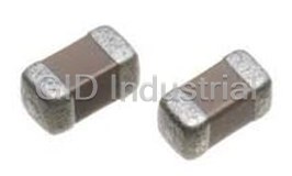
TDK C2012X7R1A106K Multilayer Ceramic Capacitors. MLCC - SMD/SMT | 10uF | 10V Rated Voltage

TDK C3216X7S0J226M160AB Multi-layer Cermaic Chip Capacitor. 22uF | 6.3V | 20% Tolerance | Surface Mo...
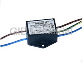
TDK PBW-1206-33 Filter Elements - Attenuates conductive noise from switching power supplies, Leakage...

Request a Quote

The quote request has been received
Close

Facing challenges or have inquiries? Feel free to contact us!
Call Us +1-469-283-2440
What they say about us
FANTASTIC RESOURCE
One of our top priorities is maintaining our business with precision, and we are constantly looking for affiliates that can help us achieve our goal. With the aid of GID Industrial, our obsolete product management has never been more efficient. They have been a great resource to our company, and have quickly become a go-to supplier on our list!
Bucher Emhart Glass
EXCELLENT SERVICE
With our strict fundamentals and high expectations, we were surprised when we came across GID Industrial and their competitive pricing. When we approached them with our issue, they were incredibly confident in being able to provide us with a seamless solution at the best price for us. GID Industrial quickly understood our needs and provided us with excellent service, as well as fully tested product to ensure what we received would be the right fit for our company.
Fuji
HARD TO FIND A BETTER PROVIDER
Our company provides services to aid in the manufacture of technological products, such as semiconductors and flat panel displays, and often searching for distributors of obsolete product we require can waste time and money. Finding GID Industrial proved to be a great asset to our company, with cost effective solutions and superior knowledge on all of their materials, it’d be hard to find a better provider of obsolete or hard to find products.
Applied Materials
CONSISTENTLY DELIVERS QUALITY SOLUTIONS
Over the years, the equipment used in our company becomes discontinued, but they’re still of great use to us and our customers. Once these products are no longer available through the manufacturer, finding a reliable, quick supplier is a necessity, and luckily for us, GID Industrial has provided the most trustworthy, quality solutions to our obsolete component needs.
Nidec Vamco
TERRIFIC RESOURCE
This company has been a terrific help to us (I work for Trican Well Service) in sourcing the Micron Ram Memory we needed for our Siemens computers. Great service! And great pricing! I know when the product is shipping and when it will arrive, all the way through the ordering process.
Trican Well Service
GO TO SOURCE
When I can't find an obsolete part, I first call GID and they'll come up with my parts every time. Great customer service and follow up as well. Scott emails me from time to time to touch base and see if we're having trouble finding something.....which is often with our 25 yr old equipment.
ConAgra Foods