

 Manufacturers
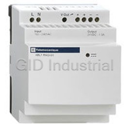
SCHNEIDER ELECTRIC ABL7RE2405

Description
Schneider Electric ABL7RE2405 24VDC Output Voltage, 120W 5A Auto Reset Single Phase Regulated Switch Mode Power Supply
Part Number
ABL7RE2405
Price
Request Quote
Manufacturer
SCHNEIDER ELECTRIC
Lead Time
Request Quote
Category
PRODUCTS - A
Features
- A high degree of output voltage stability
- A wide range of permitted input voltages (100–240 Vac), without any adjustment
- Anti-harmonics filter (PFC) according to EN 61000-3-2
- Compact size
- Considerably reduced weight in comparison to competition 1.15–4.85 lb. (0.52–2.19 kg)
- Good performance
- Integrated overload, short circuit, over voltage and under voltage protection
- The most compact offer of the market: 3 A/72 W in 27 mm
- UL/CSA certifications
Datasheet

Extracted Text
PHASEO Power Supplies ABL7 Catalog Class 8440 April 04 CONTENTS Description Page For ABL7 Power Supplies Product Description . . . . . . . . . . . . . . . . . . . . . . . . . . . . . . . . . . . . . . . . . . . . . . . . 2–7 Selection . . . . . . . . . . . . . . . . . . . . . . . . . . . . . . . . . . . . . . . . . . . . . . . . . . . . . . . . . . . 8 Specifications and Characteristics . . . . . . . . . . . . . . . . . . . . . . . . . . . . . . . . . . . . 9–11 Technical Overview . . . . . . . . . . . . . . . . . . . . . . . . . . . . . . . . . . . . . . . . . . . . . . . 12–16 Dimensions and Wiring Diagrams. . . . . . . . . . . . . . . . . . . . . . . . . . . . . . . . . . . . 17–18 For AS-Interface Power Supplies Product Description . . . . . . . . . . . . . . . . . . . . . . . . . . . . . . . . . . . . . . . . . . . . . . . . . 19 Selection . . . . . . . . . . . . . . . . . . . . . . . . . . . . . . . . . . . . . . . . . . . . . . . . . . . . . . . . . . 19 Specifications and Characteristics . . . . . . . . . . . . . . . . . . . . . . . . . . . . . . . . . . . . . . 20 Technical Overview . . . . . . . . . . . . . . . . . . . . . . . . . . . . . . . . . . . . . . . . . . . . . . . . . . 21 Dimensions and Wiring Diagrams. . . . . . . . . . . . . . . . . . . . . . . . . . . . . . . . . . . . . . . 22 Catalog Number Index . . . . . . . . . . . . . . . . . . . . . . . . . . . . . . . . . . . . . . . . . . . . . . . 23 PHASEO™ Power Supplies Product Description Product Descriptions The characteristics to be taken into account when selecting a power supply are: the required output voltage and current, the supply voltage available in the installation. An initial selection can be made using the table on page 3. This may however result in several products being selected as suitable. Other selection criteria must therefore be taken into account. Power Supply Voltage The Phaseo™ range is the solution because it guarantees precision within 4% of the output voltage, whatever the load current and input voltage. In addition, the wide input voltage range of Phaseo™ power supplies allows connection to all voltage supplies within the nominal range, without any adjustment. The Phaseo™ RP and CEM families can also be connected to 110 Vdc and 220 Vdc supply voltages. Short Circuit Protection Phaseo™ power supplies are equipped with an electronic protection device. This protection device resets itself automatically on elimination of the fault, which avoids having to take any action or change a fuse. In addition, the Phaseo™ ABL7RP / UES / UPS power supplies allow the user to select the reset mode in the event of a fault: in the “AUTO” position, resetting is automatic, in the “MANU” position, resetting occurs after elimination of the fault and after switching the supply power off and back on. This feature allows Phaseo™ ABL7RP / UES / UPS power supplies to be used in installations where the risks associated with untimely restarting are significant. Phase Failure In the event of failure of one phase, the 3-phase ABL7UES / UPS power supplies switch to relaxation mode for as long as the input voltage is < 450 V. For operation on higher voltages (e.g. 480 V), use of an upstream GV2 type residual current protection device is recommended. Electromagnetic Compatibility Levels of conducted and radiated emissions are defined in standards EN 55011 and EN 55022. The majority of products in the Phaseo™ range have class B certification and can be used without any restrictions, due to their low emissions. ABL7CEM24003 and ABL7CEM24006 power supplies have class A certification. Power Factor The current drawn by a power supply is not sinusoidal. This leads to the existence of harmonic currents which pollute the voltage supply. Regulated switch mode supplies always produce harmonic currents; a filter circuit (Power Factor Correction or PFC) must therefore be added to comply with standard EN 61000-3-2. Phaseo™ ABL7RP and ABL7UES / UPS power supplies conform to standard EN 61000-3-2 and can therefore be connected directly to public voltage power supplies. 2 5/2004 © 2000-2004 Schneider Electric All Rights Reserved PHASEO™ Power Supplies Product Description Device type ABL7CEM ABL7RM ABL7RE ABL7RP ABL7UES / UPS ASIABL Regulated switch mode for Single-phase, regulated switch mode 3-phase regulated switch mode AS-Interface power supplies Supplies for dc control circuits Functions Industrial Industrial or commercial Industrial, commercial or applications, low applications on sites Industrial applications. Industrial applications. Simple, low power residential applications. and medium sensitive to supply In-line continuous process Applications Supply of dc voltage necessary equipment. Modular format allowing power. Machine interference. equipment, machine tools, for AS-Interface systems. integration into panels. equipment Protection against injection presses, etc. applications. accidental restarting. 7 to 30 W 22 W 30 W 48 to 240 W 60 to 240 W 120 to 960 W 72 W 145 W 2 x 72 W Nominal power 100 to 240 Vac 100 to 240 Vac single single-phase 100 to 240 Vac 100 to 240 Vac phase, Input voltage 3 x 400 to 520 Vac 3-phase 100 to 240 Vac single-phase 110 to 220 Vdc single-phase single-phase 110 to 220 Vdc compatible (2) compatible (1) 12 Vdc 24 Vdc 12, 24 Vdc or 48 V 24 Vdc 24 Vdc adjustable 24 Vdc adjustable 24 Vdc adjustable 30 Vdc Output voltage adjustable adjustable adjustable adjustable Technology Primary switch mode electronic power supplies. Integrated, against Integrated, against overloads and Integrated, against overloads Secondary overloads and short- Integrated, against overloads and short-circuits, with automatic reset. short-circuits, with manual and and short-circuits, over voltage circuits, with manual and protection automatic reset. and under voltage. automatic reset. Signalling Output indicator lamp. Output and input indicator lamp. Output indicator lamp. Output and input indicator lamps Other Connection by lug- Anti-harmonic distortion Available with ground fault –– Anti-harmonic distortion filter clamps possible filter protection characteristics 35 mm DIN rail 35 mm DIN rail 5 A, 10 A versions - 35 mm DIN rail Mounting 35 mm DIN rail 35 mm DIN rail or panel mount or panel mount 20 A, 40 A versions - panel mount UL508 UL508 UL508 UL508 EN 50081-2, EN 50081-2, UL508 UL508 Conforming to EN 50081-2, EN 50081-2, IEC 61000-6-2 IEC 61000-6-2, IEC 61000-6-2, EN 50081-2, EN 50082-2, EN 50081-2, IEC 61000-6-2, IEC 61000-6-2, (EN 50082-2), IEC 60950, standards (EN 50082-2), (EN 50082-2), EN 60950,IEC 61000-3-2 EN 55022 class B EN 60950 EN61131-2 / A11 IEC 60950 IEC 60950, 61000-3-2 Approvals cULus, TÜV, CE UL, CSA, TÜV, CE UL, CSA, TÜV, CTick, CE cULus, cCSAus, CE UL, CSA, TÜV, CE 45 719 Pages 6 Selection According to Applications Characteristics Type of supply Single-phase 3-phase 3 x 400 to 520 V, 50 / 60 Hz 100 to 240 Vac 50 / 60 Hz, 110 to 220 Vdc (1) (2), Wide range Supply Voltage Wide range Permissible variation 85 to 264 V, 47 to 63 Hz / 100 to 250 Vdc (1), 105 to 370 Vdc (2) 340 to 550 V / 47 to 63 Hz 12 V 48 V 24 V 24 V 24 V Output voltage 0.3 A ABL7CEM24003 0.6 A ABL7CEM24006 1.2 A ABL7CEM24012 1.3 A ABL7RM2401 1.9 A ABL7RM1202 Output current 2 A ABL7RE2402 3 A ABL7RP4803 ABL7RP2403 ABL7RE2403 5 A ABL7RP1205 ABL7RP2405 ABL7RE2405 ABL7UES24050 10 A ABL7RP2410 ABL7RE2410 ABL7UPS24100 20 A ABL7UPS24200 40 A ABL7UPS24400 Yes (not applicable for ABL7CEM, and ABL7RM)No Yes Compliance with EN61000-3-2 Yes Yes Yes Automatic or manual restart on ABL7RP Integrated automatic protection Automatic restart Automatic or manual restart Automatic restart only on ABL7CEM and ABL7RM (1) Vdc values for ABL7RP power supplies, not indicated on the product. (2) Vdc values for ABL7CEM power supplies, not indicated on the product. 3 5/2004 © 2000-2004 Schneider Electric All Rights Reserved PHASEO™ Power Supplies Product Description ABL7CEM ABL7 POWER SUPPLIES The ABL7 range of power supplies is designed to provide the dc voltage necessary for the control circuits of automation system equipment. Split into four families, this range meets all the needs encountered in industrial, commercial and residential applications. Single-phase or 3-phase, of the electronic switch mode type, they provide a quality of output which is suitable for the loads supplied and compatible with the power supply available in the equipment. Protection devices are often used with these power supplies for total safety. Phaseo™ Switch Mode Power Supplies These switch mode power supplies are totally electronic and regulated. The use of electronics makes it possible to significantly improve the performance of these power supplies which offer: compact size integrated overload, short-circuit, over voltage and under voltage protection a very wide range of permissible input voltages, without any adjustment a high degree of output voltage stability good performance LED indicators on the front panel Phaseo™ power supplies are available in single-phase and 3-phase versions. They deliver a voltage which is precise to ≤ 4 %, whatever the load and type of power supply, within a range of 85 to 264 V for single-phase, or 340 to 550 V for 3-phase. Conforming to IEC standards and UL and CSA certifications, they are suitable for universal use. The inclusion of overload and short-circuit protection makes downstream protection unnecessary if discrimination is not required. ABL7CEM Compact Switch Mode Power Supplies The ABL7CEM single phase regulated switching power supplies are designed to provide the dc voltage necessary for most simple circuits. These power supplies are totally electronic and regulated. The use of electronics makes it possible to significantly improve the performance of these power supplies. They provide: Compact size Integrated overload, short circuit and over voltage protection A wide range of permitted input voltages, (100–240 Vac, 110–220 Vdc) without any adjustment A high degree of output voltage stability (± 2% max) 3 versions from 0.3 A (7 w) to 1.2 A (30 w) All versions are 1.77" (45 mm) wide Output voltage adjustable from 90–110% of the nominal 24 Vdc (21.6–26.4 Vdc) Designed to accept stranded or solid wire and forked or ring tongued connectors LED indicating presence of the DC output voltage These power supplies can be either 35 mm DIN rail or panel mounted Designed for use in an indoor enclosure Large screw heads for easier wiring These power supplies, which are accurate to within ± 2 % regardless of the load or the type of supply voltage, within the range of 85–264 Vac. The inclusion of overload and short circuit protection makes downstream protection unnecessary in most applications. All products have an output voltage adjustment potentiometer (21.6–26.4 %) which allows for compensation of any line voltage drop in installations with long runs. The ABL7CEM products are excellent for typical automation, low power applications. The ABL7CEM products are suitable for use in automation system environments based on the Nano and Twido PLCs or in any automation system configuration requiring a 24 Vdc supply. 4 5/2004 © 2000-2004 Schneider Electric All Rights Reserved PHASEO™ Power Supplies Product Description ABL7RM ABL7RM Modular Switch Mode Power Supplies The ABL7RM modular regulated switching power supplies are designed to provide the dc voltage necessary for equipment control circuits and meet the needs encountered in industrial, commercial, and residential applications. These single-phase, modular, electronic switching power supplies provide a quality of output current which is suitable for the loads supplied and compatible with the Zelio logic relays. Clear guidelines are given on selecting the upstream protection devices (see page 15) which are often used with them, thus providing a comprehensive solution. Switching power supplies are totally electronic and regulated. The use of electronics makes it possible to significantly improve the performance of these power supplies, which offer: Compact size Integrated overload, short-circuit, over voltage and under voltage protection A very wide range of permitted input voltages (100–240 Vac), without any adjustment A high degree of output voltage stability Good performance Considerably reduced weight (0.40 lb.) A modular format allowing incorporation into control panels These Phaseo™ power supplies deliver a voltage which is accurate within ± 3 or 4% depending on voltage, regardless of load and supply voltage, within a supply voltage range of 85–264 Vac. They are suitable for general use, are UL listed and CSA certified, and conform to IEC standards. The inclusion of overload and short-circuit protection makes downstream protection unnecessary if discrimination is not required. The power supplies are equipped with an output voltage adjustment potentiometer allowing you to compensate for any line voltage drops in installations with long cable runs. 12 Vdc device 12–14.4 Vdc 24 Vdc device 24–28.8 Vdc These power supplies are designed for direct mounting on 35 mm and 75 mm 7 DIN rail, or direct panel mounting by means of retractable mounting feet. There are two single-phase power supplies available: ABL7RM2401 (24 Vdc/1.3 A) ABL7RM1202 (12 Vdc/1.9 A) Description 5 1 2 3 2 1. 2.5 mm screw terminal for connection of the incoming ac supply voltage. 2. Output voltage adjustment potentiometer. 2 3. 2.5 mm screw terminal for connection of the output voltage. 4 4. LED indicating presence of the dc output voltage. 5. Retractable mounting feet. 5 5 5/2004 © 2000-2004 Schneider Electric All Rights Reserved PHASEO™ Power Supplies Product Description ABL7RE and ABL7RP ABL7RE and ABL7RP Single Phase Switch Mode Power Supplies The ABL7RE and ABL7RP single phase regulated switching power supplies are designed to provide the dc voltage necessary for most control system circuits. These power supplies are totally electronic and regulated. The use of electronics makes it possible to significantly improve the performance of these power supplies. They provide: Compact size Integrated overload, short circuit, over voltage and under voltage protection A wide range of permitted input voltages (100–240 Vac), without any adjustment A high degree of output voltage stability Good performance Considerably reduced weight in comparison to competition 1.15–4.85 lb. (0.52–2.19 kg) These power supplies, which are accurate to within ± 3 % regardless of the load or the type of supply voltage, within the range of 85–264 Vac. The inclusion of overload and short circuit protection makes downstream protection unnecessary in most applications. They have an output under voltage control which will cause the power supply to trip if the output voltage of a 24 Vdc supply drops below 19 Vdc, to ensure that the voltage is always usable by the devices being supplied. All products have an output voltage adjustment potentiometer (24 to 28.8 V on a 24 Vdc supply) which allows for compensation of any line voltage drop in installations with long runs. The ABL7RE products are excellent for typical industrial applications. The ABL7RP products are for general purpose applications. These supplies have an input filter (Power Factor Correction or PFC) which allows them to be used in commercial environments. They have 2 operating modes: “AUTO” mode which automatically restarts as soon as the fault is cleared. “MANU” mode which requires the power supply to be reset before restarting is possible. Resetting is achieved by switching off the supply voltage and reapplying it. Harmonics (Power Factor) – The current drawn by a power supply is non-sinusoidal. This leads to the existence of harmonic currents which pollute the main supply. European standard EN 61000-3-2 limits the harmonic currents produced by power supplies. This standard covers all devices of more the 75 W, drawing up to 16 A per phase, and connected directly to the utilities. Devices connected downstream of a private, low voltage, general transformer are excluded. However, switching power supplies produce harmonic current. Therefore, a filter circuit (PFC) must be added to the circuit when using an ABL7RE power supply to comply with standard EN 61000-3-2. The ABL7RP power supplies also conform to the EN 61000-3-2 standard and can be connected directly to the public power supply system. Input LED—When illuminated, this LED indicates the supply voltage is present. Output LED—This LED indicates if a fault has occurred. Input LED Steady: normal voltage out Output LED Flashing: overload or short circuit 6 5/2004 © 2000-2004 Schneider Electric All Rights Reserved PHASEO™ Power Supplies Product Description ABL7RM ABL7UES AND ABL7UPS Three Phase Switch Mode Power Supplies The ABL7UES / UPS three phase regulated switching power supplies are designed to provide the dc voltage necessary for most control system circuits. These power supplies are totally electronic and regulated. The use of electronics makes it possible to significantly improve the performance of these power supplies. They provide: Compact size Integrated overload, short circuit, over voltage and under voltage protection A wide range of permitted input voltages (400–520 Vac), without any adjustment A high degree of output voltage stability Good performance Considerably reduced weight in comparison to competition 2.87–9.92 lb. (1.3–4.5 kg) These power supplies, which are accurate to within ± 1 % regardless of the load or the type of supply voltage, within the range of 3 x 400 to 520 Vac with power between 120 W (5 A) and 960 W (40 A). The inclusion of overload and short circuit protection makes downstream protection unnecessary in most applications. They have an output under voltage control which will cause the power supply to trip if the output voltage of a 24 Vdc supply drops below 19 Vdc, to ensure that the voltage is always usable by the devices being supplied. All products have an output voltage adjustment potentiometer (24 to 27.8 V) which allows for compensation of any line voltage drop in installations with long runs. The ABL7UES / UPS products are excellent for typical industrial applications. These supplies have an input filter (Power Factor Correction or PFC) which allows them to be used in commercial environments. They have 2 operating modes: “AUTO” mode which automatically restarts as soon as the fault is cleared. “MANU” mode which requires the power supply to be reset before restarting is possible. Resetting is achieved by switching off the supply voltage and reapplying it. The ABL7UES / UPS products are suitable for use in automation system environments based on the Premium and Quantum PLCs or in any automation system configuration requiring a 24 Vdc supply. They can be used in industrial applications, for all in-line or continuous process equipment, machine tools, and injection presses, etc. 7 5/2004 © 2000-2004 Schneider Electric All Rights Reserved PHASEO™ Power Supplies Selection Selection Input Voltage Output Nominal Nominal Automatic Conforms to standard Catalog Weight 47 to 63 Hz voltage power current protection reset EN 61000-3-2 Number lb. (kg) Single-phase Modular Regulated Switching Power Supplies ABL7RM ABL7RM 100 to 240 Vac 12 Vdc 22 W 1.9 A auto no ABL7RM1202 0.4 (0.18) single-phase 24 Vdc 30 W 1.3 A auto no ABL7RM2401 0.4 (0.18) wide range Single-phase Regulated Switch Mode Power Supplies ABL7CEM 7 W 0.3 A auto no ABL7CEM24003 0.33 (0.15) 100 to 240 Vac single-phase 24 Vdc 15 W 0.6 A auto no ABL7CEM24006 0.40 (0.18) wide range 110 to 220 Vdc (1) 30 W 1.2 A auto no ABL7CEM24012 0.49 (0.22) ABL7CEM Single-phase Regulated Switch Mode Power Supplies ABL7RE 48 W 2 A auto no ABL7RE2402 1.15 (0.52) 100 to 240 Vac 72 W 3 A auto no ABL7RE2403 1.15 (0.52) single-phase 24 Vdc 120 W 5 A auto no ABL7RE2405 2.20 (1.00) wide range 240 W 10 A auto no ABL7RE2410 4.85 (2.20) ABL7RE2405 ABL7RP2405 ABL7RP4803 Single-phase Regulated Switch Mode Power Supplies ABL7RP 12 Vdc 60 W 5 A auto/man yes ABL7RP1205 2.20 (1.00) 72 W 3 A auto/man yes ABL7RP2403 1.15 (0.52) 100 to 240 Vac single-phase 24 Vdc 120 W 5 A auto/man yes ABL7RP2405 2.20 (1.00) wide range 110 to 220 Vdc (1) 240 W 10 A auto/man yes ABL7RP2410 4.85 (2.20) 48 Vdc 144 W 3 A auto/man yes ABL7RP4803 2.20 (1.00) 3-phase Regulated Switch Mode Power Supplies ABL7UES / UPS 120 W 5 A auto/man yes ABL7UES24050 2.87 (1.30) 240 W 10 A auto/man yes ABL7UPS24100 2.87 (1.30) 3 x 400 to 520 Vac 24 Vdc 480 W 20 A auto/man yes ABL7UPS24200 5.07 (2.30) 960 W 40 A auto/man yes ABL7UPS24400 9.92 (4.50) ABL7UPS24200 (1) Compatible Vdc input voltage not indicated on the product. ABL7RM E164866 NRAQ E164866 NRAQ7 203359 5311 05 ABL7CEM E164867 NMTR E164867 NMTR7 ABL7RE, RP E164867 NMTR 204701 5311 03 ABL7UES, UPS E164353 NKCR E164353 NKCR7 1467190 5311 06 1467190 5311 86 All have: All except ABL7UES / UPS are SEMI F47 Compliant and 8 5/2004 © 2000-2004 Schneider Electric All Rights Reserved PHASEO™ Power Supplies Specifications and Characteristics Specifications and Characteristics Specifications ABL7RM1202 ABL7RM2401 Catalog Number cULus, CSA, TÜV, CE Approvals o Conforming to Standards UL508, CSA 22.2 N 950 Safety IEC / EN 60950 - IEC / EN 61131-2 / A11 EMC EN 50081-2, IEC 61000-6-2 (EN 50082-2) Input Circuit Rated values 100 to 240 Vac 85 to 264 Vac Permissible values 47 to 63 Hz Permissible frequencies Efficiency at nominal load > 80 % 0.57 A @ 120 V / 0.37 A @ 240 V 0.74 A @ 120 V / 0.45 A @ 240 V Current consumption < 20 A Current (inrush) Power factor 0.6 0.98 Output Circuit Green LED LED indication 12 Vdc 24 Vdc Nominal output voltage 1.9 A 1.3 A Nominal output current Precision Output voltage Adjustable, from 100 to 120 % Line and load regulation ± 4 % ± 3 % Residual ripple - interference < 200 mV < 250 mV Micro-breaks Holding time at I max and Ve min > 10 ms Protection Short-circuit Permanent / thermal protection Overcurrent, cold-state < 1.7 A < 1.6 A Undervoltage < 10.5 V < 19 V Characteristics Connections 2 2 Input 1 - #14 AWG (1 x 2.5 mm ) or 2 - #16 AWG (2 x 1.5 mm ) screw terminals 2 2 Output 1 - #14 AWG (1 x 2.5 mm ) or 2 - #16 AWG (2 x 1.5 mm ) screw terminals 5.4 lb-in (0.6 Nkm) Tightening torque Environment Storage Temperature -13 to 158 °F (- 25 to +70 °C) Operating Temperature -13 to 131 °F (-25 to +55 °C) Maximum Relative Humidity 95% Degree of Protection IP20 conforming to IEC 60529 Vibrations Conforming to EN 61131-2, IEC 60068-2-6 test Fc Vertical Operating position Connections Serial Not Possible Parallel Possible (same references) Dielectric strength Input / output 3000 V / 50 / 60 Hz / 1 min. Class II without ground terminal (double insulated) Protection class conforming to VDE 0106 1 Yes (internal, not replaceable) Input fuse incorporated EN 50081-2 (Generic) Emissions Conducted / radiated EN 55011 / EN 55022 cl.B IEC 61000-6-2 (Generic) Immunity Electrostatic Discharge EN 61000-4-2 (4 kV contact / 8 kV air) Electromagnetic EN 61000-4-3 level 3 (10 V / m) Conducted Interference EN 61000-4-4 level 3 (2 kV), EN 61000-4-6 (10 V) Supply Interference EN 1000-4-11 9 5/2004 © 2000-2004 Schneider Electric All Rights Reserved PHASEO™ Power Supplies Specifications and Characteristics Specification and Characteristics Specifications ABL7CEM ABL7RE ABL7RP Catalog Number cULus, TÜV, CE UL, CSA, TÜV, CTick , CE UL, CSA, TÜV, CTick , CE Approvals Conforming to standards UL 508 UL 508, CSA 22.2 n° 950 UL 508, CSA 22.2 n° 950 Safety IEC / EN 60950 EMC EN 50081-2, EN 50082-2 EN 50081- 2, IEC 61000-6-2 (EN 50082-2) Low frequency harmonic currents No No EN 61000-3-2 Input Circuit LED indication None Orange LED Orange LED Input voltages 100 to 240 Vac, 100 to 240 Vac, Rated values 100 to 240 Vac 110 to 220 Vdc compatible (1) 110 to 220 Vdc compatible (1) 85 to 264 Vac, 85 to 264 Vac, Permissible values 85 to 264 Vac single-phase 105 to 370 Vdc compatible (1) 100 to 250 Vdc compatible (1) Permissible frequencies 47 to 63 Hz Efficiency at nominal load > 70 % > 85 % 0.5 A (60 W) / 0.5 A (72 W) / 0.7 A 0.1 A (7 W) / 0.2 A (15 W) / 0.45 A 0.7 A (48 W) / 0.9 A (72 W) Ue = 240 V (120 W) / 0.7 A (144 W) / (30 W) 1.4 A (120 W) / 2.5 A (240 W) 1.4 A (240 W) Current consumption 0.78 A (60 W) / 0.87 A (72 W) / 0.15 A (7 W) / 0.26 A (15 W) / 1.13 A (48 W) / 1.57 A (72 W) Ue = 120 V 1.39 A (120 W) / 1.39 A (144 W) / 0.59 A (30 W) 2.44 A (120 W) / 4.35 A (240 W) 2.78 A (240 W) Current at switch-on < 50 A < 30 A Power factor 0.45 approx. 0.65 approx. 0.98 approx. Output Circuit Green LED Green LED Green LED LED indication Nominal output voltage (U out) 24 Vdc 12, 24 and 48 Vdc 0.3 A / 0.6 A / 1.2 A 2 A / 3 A / 5 A / 10 A 3 A / 5 A / 10 A Nominal output current Output voltage Adjustable, from 90 to 110 % Adjustable, from 100 to 120 % 2 % max. ± 3 % Line and load regulation Residual ripple - interference < 200 mV (peak-peak) Micro-breaks Holding time at I max and Ve min. > 20 ms > 10 ms > 20 ms Permissible inrush current (U out >19 V) (See curves page 16) Temporary overloads Permanent / automatic restart or Short-circuit protection Permanent / automatic restart Permanent / automatic restart manual restart on product 1.05 In 1.1 In Overload protection Overvoltage protection U > 1.2 Tripping if U > 1.5 Un – Tripping if U < 0.8 Un Undervoltage protection Characteristics 2 Input connection 2 - #14 AWG (2 x 2.5 mm )+ ground 2 2 2 - #14 AWG (2 x 2.5 mm ) 2 - #14 AWG (2 x 2.5 mm )+ ground, multiple output, depending on model Output connection Tightening torque 7.0 lb-in (0.8 Nkm) 5.4 lb-in (0.6 Nkm) - 13 to + 158 °F (- 25 to + 70 °C) Storage temperature 14 to + 140 °F (- 10 to + 60 °C) - 32 to + 140 °F (0 to + 60 °C) derating as from 122 °F (50 °C), mounted derating as from 122 °F (50 °C), Operating temperature vertically mounted vertically 20 to 90 % 95 % without condensation or dripping water Maximum relative humidity Degree of protection IP 20 conforming to IEC 60529 Conforming to EN 61131-2 Vibrations Operating position Vertical and horizontal (see p. 13) Vertical > 100 000 h MTBF at 40 ° Series connection Possible No Possible - maximum temperature 122 °F (50 °C) Parallel connection Dielectric strength Input / output 3000 V / 50 Hz 1 min. 3000 V / 50 Hz 1 min. Input / ground 2000 V / 50 Hz 1 min. 3000 V / 50 Hz 1 min. Output / ground (and output / 500 V / 50 Hz 1 min. 500 V / 50 Hz 1 min. output) Input fuse incorporated Yes (internal, not replaceable) EN 50081-1 (Generic) Emissions EN 55011 / EN 55022 cl.A (7 &15 W) Conducted EN 55011 / EN 55022 cl.B EN 55011 / EN 55022 cl.B (30 W) Radiated EN 55011 / EN 55022 cl.B Immunity IEC 61000-6-2 (Generic) Electrostatic discharge EN 61000-4-2 (4 kV contact / 8 kV air) Electromagnetic EN 61000-4-3 level 3 (10 V / m) Conducted interference EN 61000-4-4 level 3 (2 kV), EN 61000-4-5, EN 61000-4-6 level 3, EN 61000-4-8 level 4. Supply interference EN 1000-4-11 (Voltage drops and cuts) (1) Vdc compatible input voltage, not indicated on the product. 10 5/2004 © 2000-2004 Schneider Electric All Rights Reserved PHASEO™ Power Supplies Specifications and Characteristics Specifications and Characteristics Specifications ABL7UES24050, ABL7UPS24p Catalog Number Approvals cULus, cCSAus, CE Conforming to standards UL508 Safety EN 60950, FELV EMC EN 50081-1, EN 50082-2 Low frequency harmonic currents EN 61000-3-2 Input Circuit LED indication None Input voltages Rated values 3 x 400 to 520 Vac Permissible values 3 x 340 to 550 Vac Permissible frequencies 50 to 60 Hz Efficiency at nominal load > 90 % Current consumption (Ue = 400 V) 0.33 A @ 120 W / 0.65 A @ 240 W / 1.2 A @ 480 W / 1.7 A @ 960 W Current at switch-on < 15 A Power factor 0.7 @ 120 W / 0.7 / 0.9 @ 960 W 2-phase operating mode Relaxation if input voltage < 450 Vac Output Circuit LED indication Green LED Nominal output voltage (U out) 24 Vdc Nominal output current 5 / 10 / 20 / 40 A Adjustable 100 to 116 % Output voltage 1 % max. Line and load regulation Residual ripple - interference < 200 mV (peak-peak) Micro-breaks Holding time at I max and Ve min. between 8 and 13 ms Temporary overloads Permissible inrush current (U out > 19 V) See curves, page 16 Short-circuit protection Permanent / automatic or normal restart Overload protection 1.05 In < 50 ms Overvoltage protection 28.5 V typical 19 V typical Undervoltage protection Characteristics 2 2 - #16-14 AWG (2 x 1.5 to 2.5 mm ) + ground Input connection Output connection 2 UES24050, UPS24100 2 - #16-14 AWG (2 x 1.5 to 2.5 mm ) 2 UPS24200 2 - #12-10 AWG (2 x 4 to 6 mm ) 2 UPS24400 2 - #12-8 AWG (2 x 4 to 10 mm ) Tightening torque UES24050, UPS24100 Input: 5.4 lb-in (0.6 Nkm) / Output: 4.5 lb-in (0.5 Nkm) UPS24200 Input: 5.4 lb-in (0.6 Nkm) / Output: 5.4 lb-in (0.6 Nkm) UPS24400 Input: 5.4 lb-in (0.6 Nkm) / Output: 10.8 lb-in (1.2 Nkm) Ambient conditions Storage temperature -13 to + 158 °F (- 25 to + 70 °C) Operating temperature 32 to + 140 °F (0 to + 60 °C) Humidity relative maximal 30 to 90 % Degree of protection IP 20 Vibrations Conforming to EN 61131-2 Vertical Operating position MTBF > 100 000 h Series connection Possible - 2 power supplies max. Parallel connection Possible - 2 power supplies max. Dielectric strength Input / output 3750 V / 50 and 60 Hz 1 mn Input / ground 3500 V / 50 and 60 Hz 1 mn Output / ground (and output / output) 500 V / 50 and 60 Hz 1 mn Input fuse incorporated No Emissions Conducted / radiated EN 55011 / EN 5022 - Class B Immunity Electrostatic discharge EN 61000-4-2 (4 kV contact / 8 kV air) Electromagnetic EN 61000-4-3 level 3 (10 V / m) EN 61000-4-4 level 3 (2 kV), EN 61000-4-5, EN 61000-4-6 level 3, Conducted interference EN 61000-4-8 level 4 Supply interference EN 61000-4-11 (Voltage drops and cuts) 11 5/2004 © 2000-2004 Schneider Electric All Rights Reserved PHASEO™ Power Supplies Technical Overview Technical Overview DERATING ABL7RM POWER SUPPLIES The ambient temperature is a determining factor which limits the power that an electronic power supply can deliver continuously. If the temperature around the electronic components is too high, their life will be significantly reduced. Conversely, a power supply can deliver more than its rated power if the ambient temperature remains well below the nominal operating temperature. The maximum ambient temperature for Phaseo™ power supplies is 131 °F (55 °C). Below this temperature, it is possible to receive up to 110 % of the nominal power. The graph below shows the power (in relation to the nominal power) which the power supply can deliver continuously, according to the ambient temperature. 120 110 100 90 80 70 60 50 131 32 50 68 86 104 122 140 158 (55) (0) (10) (20) (30) (40) (50) (60) (70) Maximum Operating Temperature—°F (°C) Derating should also be considered in the following extreme operating conditions: — Intensive operation (output current permanently close to the nominal current, combined with a high ambient temperature) — output voltage set above 24 V (to compensate for line voltage drops, for example) — parallel connection to increase the total power 12 5/2004 © 2000-2004 Schneider Electric All Rights Reserved Percent Rated Power PHASEO™ Power Supplies Technical Overview Technical Overview DERATING ABL7CEM, RE, RP, UES, AND UPS The ambient temperature is a determining factor which limits the power that an electronic power supply can deliver continuously. A temperature which is too high around the electronic components significantly reduces their life. However, if the ambient temperature remains largely below the rated operating temperature, then a power supply can deliver more than its nominal power. The rated ambient temperature for Phaseo™ power supplies is 122 °F (50 °C). Above 122 °F (50 °C), a derating is necessary up to a maximum temperature of 140 °F (60 °C). The graph below shows the power (in relation to the nominal power) which the power supply unit can deliver continuously, according to the ambient temperature. P/Pn (%) 140 120 100 80 3 2 1 60 50 40 20 0 32 50 68 86 104 122 140 158 (0) (10) (20) (30) (40) (50) (60) (70) Maximum operational temperature—°F (°C) 1. ABL7RE, ABL7RP, ABL7UES, ABL7UPS vertical mounting 2. ABL7CEM vertical mounting 3. ABL7CEM horizontal mounting Derating should be considered in the following extreme operating conditions: intensive operation (output current permanently close to the nominal current, combined with a high ambient temperature), output voltage set above 24 V (to compensate for line voltage drops, for example), parallel connection to increase the total power. General rules to be followed See derating information on the graph above. Example for ABL7RE: Intensive operation - without derating, from 32 °F to 122 °F (0 °C to 50 °C), - derating of nominal current by 2 % per additional °C, up to 140 °F (60 °C). The nominal power is fixed. Rise in output voltage Increasing the output voltage means that the current delivered must be reduced. The total power is equal to the sum of the powers of the power supplies used, but the maximum Parallel connection to increase the power ambient temperature for operation is 122 °F (50 °C) (except ABL7CEM) To improve heat dissipation, the power supplies must not be in contact with each other. In all cases, there must be adequate convection around the products to ensure proper cooling. Required Clearances Above and Below On Both Sides ABL7CEM – 0.39 (10 mm) ABL7RE, RP 1.96 (50 mm) 0.59 (15 mm) ABL7UES / UPS 3.93 (100 mm) 3.93 (100 mm) 13 5/2004 © 2000-2004 Schneider Electric All Rights Reserved PHASEO™ Power Supplies Technical Overview Technical Overview USING 24 Vdc Using 24 Vdc enables so-called protection installations (PELV) to be built. Using PELV is a measure designed to protect people from direct and indirect contact. Measures relating to these installations are defined in publication NF C 12-201 and in standard IEC 60364-4-41. The application of these measures to the electrical equipment in machines is defined in standard NF EN 60204-1 and requires: — the voltage used is below 60 Vdc in dry environments and below 30 V in damp environments, — the connection of one side of the PELV circuit, or one point of the source, to the equipotential protection circuit associated with higher voltages. — the use of switchgear and control gear on which measures have been taken to ensure “safety separation” between power circuits and control circuits. A safety separation is necessary between power circuits and control circuits in PELV circuits. Its aim is to warn of the appearance of dangerous voltages in 24 Vdc safety circuits. The reference standards involved are: — IEC 61558-2-6 and EN 61558-2-6 (safety transformers), — IEC 60664 (coordination of isolation). Telemecanique power supplies meet these requirements. Moreover, to ensure that these products will operate correctly in relation to the demands of their reinforced isolation, it is recommended that they be mounted and wired as indicated below: — they should be placed on a grounded mounting plate or rail, — they should be connected using flexible wires, with a maximum of two wires per connection, and tightened to the nominal torque, — conductors of the correct insulation class must be used. If the dc circuit is not connected to an equipotential protection conductor, an ground leakage detector will indicate any accidental insulation faults. OPERATING VOLTAGE The permissible tolerances for the operating voltage are listed in publications IEC 61131-2 and DIN 19240. For nominal voltage Un = 24 Vdc, the extreme operating values are from - 15 % to + 20 % of Un, whatever the supply fluctuations in the range - 10 % to + 6 % (defined by standard IEC 60038) and load variations in the range 0–100 % of In. All Telemecanique 24 Vdc power supplies are designed to provide a voltage within this range. It may be necessary to use a voltage measurement relay to detect when the normal voltage limits are being surpassed and to deal with the consequences of this. 14 5/2004 © 2000-2004 Schneider Electric All Rights Reserved PHASEO™ Power Supplies Technical Overview Technical Overview PROTECTION DEVICES For ABL7CEM, ABL7RE, ABL7RP, AND ABL7RM 120 Vac Single-phase 240 Vac Single-phase For Use With Thermal-Magnetic Circuit-Protector Thermal-Magnetic Circuit-Protector Input gG Input gG Poles Poles Current Fuse Current Fuse GB2 C60N GB2 C60N 1 GB2CB05 (0.5 A) MG17421 (0.5 A) 1 GB2CB05 (0.5 A) MG17421 (0.5 A) ABL7CEM24003 0.15 A 1 A 0.1 A 1 A 2 GB2CD05 (0.5 A) MG24516 (1.0 A) 2 GB2CD05 (0.5 A) MG24516 (1.0 A) 1 GB2CB05 (0.5 A) MG17421 (0.5 A) 1 GB2CB05 (0.5 A) MG17421 (0.5 A) ABL7CEM24006 0.26 A 1 A 0.2 A 1 A 2 GB2CD05 (0.5 A) MG24516 (1.0 A) 2 GB2CD05 (0.5 A) MG24516 (1.0 A) 1 GB2CB06 (1.0 A) MG24500 (1.0 A) 1 GB2CB06 (1.0 A) MG24500 (1.0 A) ABL7CEM24012 0.59 A 1 A 0.45 A 1 A 2 GB2CD06 (1.0 A) MG24516 (1.0 A) 2 GB2CD06 (1.0 A) MG24516 (1.0 A) 1 GB2CB07 (2.0 A) MG24501 (2.0 A) 1 GB2CB06 (1.0 A) MG24500 (1.0 A) ABL7RE2402 1.13 A 2 A 0.7 A 1 A 2 GB2CD07 (2.0 A) MG24517 (2.0 A) 2 GB2CD06 (1.0 A) MG24516 (1.0 A) 1 GB2CB07 (2.0 A) MG24501 (2.0 A) 1 GB2CB06 (1.0 A) MG24500 (1.0 A) ABL7RE2403 1.57 A 2 A 0.90 A 1 A 2 GB2CD07 (2.0 A) MG24517 (2.0 A) 2 GB2CD06 (1.0 A) MG24516 (1.0 A) 1 GB2CB08 (3.0 A) MG24502 (3.0 A) 1 GB2CB07 (2.0 A) MG24501 (2.0 A) ABL7RE2405 2.44 A 4 A 1.4 A 2 A 2 GB2CD08 (3.0 A) MG24517 (3.0 A) 2 GB2CD07 (2.0 A) MG24517 (2.0 A) 1 GB2CB12 (6.0 A) MG24504 (6.0 A) 1 GB2CB08 (3.0 A) MG24502 (3.0 A) ABL7RE2410 4.35 A 6 A 2.5 A 4 A 2 GB2CD12 (6.0 A) MG24520 (6.0 A) 2 GB2CD08 (3.0 A) MG24517 (3.0 A) 1 GB2CB06 (1.0 A) MG24500 (1.0 A) 1 GB2CB06 (1.0 A) MG24500 (1.0 A) ABL7RP1205 0.78 A 2 A 0.5 A 1 A 2 GB2CD06 (1.0 A) MG24516 (1.0 A) 2 GB2CD06 (1.0 A) MG24516 (1.0 A) 1 GB2CB07 (2.0 A) MG24501 (2.0 A) 1 GB2CB06 (1.0 A) MG24500 (1.0 A) ABL7RP2403 0.87 A 2 A 0.5 A 1 A 2 GB2CD07 (2.0 A) MG24517 (2.0 A) 2 GB2CD06 (1.0 A) MG24516 (1.0 A) 1 GB2CB07 (2.0 A) MG24501 (2.0 A) 1 GB2CB06 (1.0 A) MG24500 (1.0 A) ABL7RP2405 1.39 A 2 A 0.7 A 1 A 2 GB2CD07 (2.0 A) MG24517 (2.0 A) 2 GB2CD06 (1.0 A) MG24516 (1.0 A) 1 GB2CB09 (4.0 A) MG24503 (4.0 A) 1 GB2CB07 (2.0 A) MG24501 (2.0 A) ABL7RP2410 2.78 A 4 A 1.4 A 2 A 2 GB2CD09 (4.0 A) MG24519 (4.0 A) 2 GB2CD07 (2.0 A) MG24517 (2.0 A) 1 GB2CB07 (2.0 A) MG24501 (2.0 A) 1 GB2CB06 (1.0 A) MG24500 (1.0 A) ABL7RP4803 1.39 A 2 A 0.7 A 1 A 2 GB2CD07 (2.0 A) MG24517 (2.0 A) 2 GB2CD06 (1.0 A) MG24516 (1.0 A) 1 GB2CB06 (1.0 A) MG24500 (1.0 A) 1 GB2CB05 (0.5 A) MG17421 (0.5 A) ABL7RM1202 0.57 A 1 A 0.37 A 1 A 2 GB2CD06 (1.0 A) MG24516 (1.0 A) 2 GB2CD05 (0.5 A) MG24516 (1.0 A) 1 GB2CB06 (1.0 A) MG24500 (1.0 A) 1 GB2CB06 (1.0 A) MG24500 (1.0 A) ABL7RM2401 0.74 A 1 A 0.45 A 1 A 2 GB2CD06 (1.0 A) MG24516 (1.0 A) 2 GB2CD06 (1.0 A) MG24516 (1.0 A) For ABL7UES and ABL7UPS Wiring 400 to 520 Vac Three-phase GB2-CB GB2-CD Thermal-Magnetic For Use With Input gG Supplementary Protector Current Fuse GV2ME C60N ABL7UES24050 3 x 0.33 A GV2ME08 (2.5–4 A) MG24533 (2 A) 2 A ABL7UPS24100 3 x 0.65 A GV2ME08 (2.5–4 A) MG24533 (2 A) 2 A ABL7UPS24200 3 x 1.2 A GV2ME08 (2.5–4 A) MG24534 (3 A) 3 A ABL7UPS24400 3 x 1.7 A GV2ME08 (2.5–4 A) MG24535 (4 A) 4 A 15 5/2004 © 2000-2004 Schneider Electric All Rights Reserved PHASEO™ Power Supplies Technical Overview Technical Overview OUTPUT CHARACTERISTICS Load Limit ABL7CEM24ppp ABL7RE24pp/ABL7RPpppp and ABL7UES / UPS24pp U out U out (%) 100 % 19 V 50 % 12 I out I out 1.1 x In 1.2 x In In 1.2 x In 1 ABL7RE24pp/ABL7RPpppp 2 ABL7UPS24pp Temporary Overloads ABL7RE/ABL7RP ABL7CEM T (ms) I out T (ms) I out 100 20 I out:(0 to 100%) I out:(0 to 100%) 90 18 80 70 16 60 50 14 40 12 30 20 10 10 0 0 1.8 2 2.2 2.4 2.6 1.2 1.3 1.4 1.5 1.6 1.7 1.8 x In x In ABL7UES / UPS T (ms) 800 700 600 I out=0% I out=50% 500 400 300 Example: For an ABL7UES / UPS24ppp power supply, 50 % loaded I out=80% 250 (I out = 50 %), this power supply can withstand a current peak of 1.6 x In for 200 250 ms with an output voltage u19 V. I out=100% 100 0 1.2 1.3 1.4 1.5 1.6 1.7 1.8 x In Series or Parallel Connection Series connection Parallel connection ABL7 ABL7 ABL7 ABL7 (1) (1) 24 Vdc / 2 x I out 2 x 24 Vdc / I out Family Series Parallel ABL7CEM 2 products max (1) Not possible ABL7RE/RP 2 products max 2 products max ABL7UES / UPS 2 products max 2 products max (1) 2 Schottky diodes, 2 A/100 V, on ABL7CEM only. 16 5/2004 © 2000-2004 Schneider Electric All Rights Reserved + + + + PHASEO™ Power Supplies Dimensions Dimensions ABL7RMpppp 1.73 (44) 2.36 (60) 0.16 (4) in 2.32 (59) 2.83 (72) Dual Dimensions = mm 2.76 (70) ABL7RE24pp/ABL7RPpppp ABL7RE2402/2403 ABL7RE2405 ABL7RE2410 Common side view ABL7RP2403 ABL7RP1205/2405/4803 ABL7RP2410 Mounting on 35 and 75 mm rails 1.06 4.72 2.12 5.31 120 27 54 135 ABL7CEM24ppp ABL7CEM24006/ ABL7UES24050 Common front view ABL7CEM24003 ABL7CEM24012 ABL7UPS24100 2.75 3.74 1.77 70 95 45 Panel mounting a P 0.23 2.67 6 68 2 x M4 or 2 x Ø4.5 ABL7UPS24400 ABL7UPS24200 3.18 2.36 81 60 9.44 3.30 10.82 4.17 240 84 275 106 17 5/2004 © 2000-2004 Schneider Electric All Rights Reserved 120 3.54 (90) 4.33 (110) 4.72 2.95 120 9.05 75 230 9.52 242 3.54 (90) 4.33 (100) 4.72 120 7.75 197 8.22 4.99 209 127 4.72 120 PHASEO™ Power Supplies Wiring Diagrams Dimensions and Wiring ABL7RE2402/2403 ABL7RE2405 ABL7RE2410 ABL7RP2403 ABL7RP1205/2405/4803 ABL7RP2410 Filter Filter Filter ABL7CEM24ppp ABL7RMpppp ABL7UES / UPSppppp + + Filter L1 L2 L3 18 5/2004 © 2000-2004 Schneider Electric All Rights Reserved + N/ N N NC + L/+ L + L L N + + N/ N – L L/+ + + + + – – – + + N/ N – L/+ L + + – + + – PHASEO™ Power Supplies Product Description and Selection Product Description and Selection PE N L POWER SUPPLIES FOR AS-INTERFACE 100-240V 24 V Consistent with the standard Phaseo™ line, the range of ASIABL power supplies is designed to deliver a dc voltage, as required by networks operating under the AS-Interface protocol. Three versions are AS-i : 2,4 A ASI ABLB3002 available to meet all needs encountered in industrial applications, in enclosures, cells or floor-standing enclosures. These single-phase, electronic, switch mode power supplies guarantee the quality of the output current, in accordance with the electrical characteristics and conforming to standard EN 50295. ASIABLB300p AS-i + AS-i GND AS-i + AS-i GND Operating on a 100 to 240 Vac supply, this power supply delivers a voltage of 30 Vdc available in 2.4 (1) and 4.8 A ratings. The parallel output terminal blocks allow the bus to be connected separately to the AS-Interface AS-Interface slaves and the master. Input and output LEDs allow fast and continuous diagnostics. master module ASIABLD300p ASIABLB300p Operating on a 100 to 240 Vac supply, this power supply delivers a voltage of 30 Vdc available in 2.4 and 4.8 A ratings, and allows diagnosis and management of ground faults on AS-Interface networks. In the event of an ground fault, the Phaseo™ power supply trips out, thus stopping dialogue on the bus. Ground fault Restarting is only possible after deliberate acknowledgement of the fault. Two I/O ports are provided, Reset which may be used to monitor status. The parallel output terminal blocks are used to connect the bus PE N L + 1 2 separately to the slaves and the AS-Interface master. Input, output and fault LED’s allow fast and 100-240V Reset Fault continuous diagnostics. Fault 24 V Fault + ON AS-i : 2,4 A ASIABLM3024 OFF ASI ABLD3002 TEST RESET Operating on a 100 to 240 Vac supply, this product delivers two dc outputs which are totally independent in the way they operate. Two output voltages - 30 Vdc/2.4 A (AS-Interface supply) and 24 Vdc/3 A - are available, making it possible to supply the control equipment without an additional power supply. Input and output LEDs allow fast and continuous diagnostics. AS-i + AS-i GND AS-i + AS-i GND (2) Regulated Switch Mode Power Supplies ASIABL AS-Interface AS-Interface master Input Voltage Output Nominal Nominal Automatic Ground fault Catalog Weight module 47 to 63 Hz voltage power current protection reset detection number lb. (kg) ASIABLD300p 72 W 2.4 A auto no ASIABLB3002 1.76 (0.80) 145 W 4.8 A auto no ASIABLB3004 2.87 (1.30) 100 to 240 V 30 Vdc single-phase 72 W 2.4 A auto yes ASIABLD3002 1.76 (0.80) wide range 145 W 4.8 A auto yes ASIABLD3004 2.87 (1.30) PE N L 30 + 24 Vdc 2 x 72 W 2.4 + 3 A auto no ASIABLM3024 2.87 (1.30) 100-240V 24 V AS-i AS-i : 4,8 A ASI ABLM3024 24 V - 3 A 24 30,5 V + AS-i + AS-i GND AS-i + AS-i GND (1) File E164867 CCN NMTR ® AS-Interface 24 Vdc AS-Interface master File 204701 control module Class 5311 03 ASIABLM3024 (1) Recommended connection. (2) Required connection. 19 5/2004 © 2000-2004 Schneider Electric All Rights Reserved PHASEO™ Power Supplies Specifications and Characteristics Specifications and Characteristics Technical Specifications Catalog Number ASIABLB3002 ASIABLB3004 ASIABLD3002 ASIABLD3004 ASIABLM3024 24 Vdc Supply to the AS-Interface system Functions supply Approvals UL 508, CSA 22-2 n° 950, CE, TUV Conforming to standards Safety EN 60950, TÜV EMC EN 50081-1, IEC 61000-6-2, EN 55022 class B Low frequency harmonic currents No Input circuit Yellow LED LED indication Input voltage Rated values 100 to 240 Vac Permissible values 85 to 264 Vac Permissible frequencies 47 to 63 Hz Efficiency at nominal load > 83 % > 80 % Current consumption 0.5 1 0.5 1 1 Current at switch-on < 30 A Power factor > 0.65 Output circuit Green LED LED indication 30 Vdc (AS-Interface) 24 Vdc Nominal output voltage 2.44.8 2.44.8 2.43 Nominal output current Precision Adjustable output voltage – 100 to 120 % Line and load regulation 3 % Residual ripple - interference 300–50 mV Micro-breaks Holding time for I max and Ve min. 10 ms Protection Short-circuit Permanent/automatic restart after elimination of the fault Overload 1.1 In Overvoltage Tripping if U > 1.2 Un U > 1.5 Un Undervoltage Tripping if U < 0.95 Un U < 0.8 Un Operating characteristics Connections 2 Input 2-#14 AWG (2 x 2.5 mm ) screw terminals + ground 2 Output 2-#14 AWG (2 x 2.5 mm ) screw terminals + ground, multiple output 5.4 lb-in (0.6 Nkm) Tightening torque Environment Storage temperature - 13 to + 158 °F (- 25 to + 70 °C) Operating temperature 32 to 140 °F (0 to + 60 °C) derating 122 °F (50 °C) Maximum relative humidity 95 % (without condensation or dripping water) Degree of protection IP 20 (conforming to IEC 60529) Vibration EN 61131-2 Vertical Operating position > 100000 h conforming to Bell core, at 104 °F (40 °C) MTBF Dielectric strength Input/output 3000 V/50 Hz/1 mm Input/ground 3000 V/50 Hz/1 mm Output/ground (and input/output) 500 V/50 Hz/1 mm Yes (not interchangeable) Input fuse incorporated Emissions Conducted/radiated Class B (conforming to EN 55022) Immunity Electrostatic discharge EN 61000-4-2 (4 kV contact/8 kV air) Electromagnetic EN 61000-4-3 level 3 (10 V/m) Conducted interference EN 61000-4-4 level 3 (2 kV), EN 61000-4-6 (10 V) Supply interference EN 61000-4-11 20 5/2004 © 2000-2004 Schneider Electric All Rights Reserved PHASEO™ Power Supplies Technical Overview Technical Overview DERATING The ambient temperature is a determining factor which limits the power that an electronic power supply can deliver continuously. If the temperature around the electronic components is too high, their life will be significantly reduced. The graph below shows the power (in relation to the nominal power) which the power supply can deliver continuously, according to the ambient temperature. 140 P/Pn (%) 120 100 80 60 40 20 0 32 50 68 86 104 122 140 158 (0) (10) (20) (30) (40) (50) (60) (70) Maximum operating temperature °F (°C) PROTECTION DEVICES For AS-Interface System Power Supply 115 Vac single-phase 230 Vac single-phase Type of protection Thermal-magnetic circuit-protector Gg fuse Thermal-magnetic circuit-protector Gg fuse Single-pole GB2 CBpp 2-pole GB2 DBpp C60N GB2 DBpp C60N ASIABLB3002 GB2 pB07 MG24517 (1) 2 A GB2 DB06 MG24516 (1) 2 A ASIABLB3004 GB2 pB08 MG24518 (1) 4 A GB2 DB07 MG17453 (1) 2 A ASIABLD3002 GB2 pB07 MG24517 (1) 2 A GB2 DB06 MG24516 (1) 2 A ASIABLD3004 GB2 pB08 MG24518 (1) 4 A GB2 DB07 MG17453 (1) 2 A ASIABLM3024 GB2 pB07 MG24517 (1) 2 A GB2 DB06 MG17453 (1) 2 A (1) UL listed circuit-breaker. There must always be adequate convection around the power supply to ensure proper cooling. There must be a clear space of 1.96" (50 mm) above and below the power supply and 0.59" (15 mm) on both sides. 21 5/2004 © 2000-2004 Schneider Electric All Rights Reserved PHASEO™ Power Supplies Dimensions and Wiring Diagrams Dimensions and Wiring Diagrams Function Diagram 1 ON/OFF DDT 10 5 2 Supply N L + 1 2 AS-i + AS-i , and GND (4) AS-i + 6 8 24 V 7 9 AS-i (1) AS-i : 2,4 A 1 3 Reset 4 or (1) 3 10 Reset (1) 4 Test (3) (3) (3) (3) (2) (2) (2) (2) Fault 5 6 AS-i + AS-i AS-i GND GND AS-i + AS-i + AS-i GND GND AS-i 7 Fault + 8 2 Fault 9 Input at state 0 or contact open LED off Relay off Input at state 1 or contact closed LED on Relay on (1) 30 ms min. (2) 15 ms. (3) 20 ms. (4) NOTE: The ground fault detector will only operate if the ground (GND) terminal is connected. Dimensions Common side view ASIABLB3002 ASIABLM3024 Mounting on 35 and 75 mm rails ASIABLD3002 ASIABLp3004 4.72 2.12 3.18 120 54 81 in Dual Dimensions = mm Wiring ASIABLB300p ASIABLD300p ASIABLM3024 Set Fault detector ON/ Filter Filter Filter OFF 24 V 22 5/2004 © 2000-2004 Schneider Electric All Rights Reserved N AS-i + L AS-i GND AS-i + AS-i GND N AS-i + L AS-i GND 4.72 120 AS-i + + AS-i GND 1 2 + N L 4.72 AS-i + 120 AS-i GND AS-i + AS-i GND PHASEO™ Power Supplies Indexed Catalog Numbers ABL7RM1202 . . . . . . . . . . . . 8 ABL7RM2401 . . . . . . . . . . . . 8 ABL7CEM24003 . . . . . . . . . . 8 ABL7CEM24006 . . . . . . . . . . 8 ABL7CEM24012 . . . . . . . . . . 8 ABL7RE2402. . . . . . . . . . . . . 8 ABL7RE2403. . . . . . . . . . . . . 8 ABL7RE2405. . . . . . . . . . . . . 8 ABL7RE2410. . . . . . . . . . . . . 8 ABL7RP1205. . . . . . . . . . . . . 8 ABL7RP2403. . . . . . . . . . . . . 8 ABL7RP2405. . . . . . . . . . . . . 8 ABL7RP2410. . . . . . . . . . . . . 8 ABL7RP4803. . . . . . . . . . . . . 8 ABL7UES24050 . . . . . . . . . . 8 ABL7UPS24100 . . . . . . . . . . 8 ABL7UPS24200 . . . . . . . . . . 8 ABL7UPS24400 . . . . . . . . . . 8 ASIABLB3002 . . . . . . . . . . . 20 ASIABLB3004 . . . . . . . . . . . 20 ASIABLD3002 . . . . . . . . . . . 20 ASIABLD3004 . . . . . . . . . . . 20 ASIABLM3024. . . . . . . . . . . 20 NOTE: Protective devices are listed on pages 15 and 21. 23 © 2000-2004 Schneider Electric All Rights Reserved 05/04 Schneider Electric Schneider Electric Canada 8001 Highway 64 East 19 Waterman Avenue, Knightdale, NC 27545 M4B 1 Y2 1-888-SquareD Toronto, Ontario (1-888-778-2733) 1-800-565-6699 Catalog No. 8440CT0001R4/04 May 2004 © 2000–2004 Schneider Electric All Rights Reserved www.us.SquareD.com www.schneider-electric.ca Replaces 8440CT0001R2/03 dated 02/04
Frequently asked questions
What makes Elite.Parts unique?

What kind of warranty will the ABL7RE2405 have?
Which carriers does Elite.Parts work with?
Will Elite.Parts sell to me even though I live outside the USA?
I have a preferred payment method. Will Elite.Parts accept it?


What they say about us
FANTASTIC RESOURCE
One of our top priorities is maintaining our business with precision, and we are constantly looking for affiliates that can help us achieve our goal. With the aid of GID Industrial, our obsolete product management has never been more efficient. They have been a great resource to our company, and have quickly become a go-to supplier on our list!
Bucher Emhart Glass
EXCELLENT SERVICE
With our strict fundamentals and high expectations, we were surprised when we came across GID Industrial and their competitive pricing. When we approached them with our issue, they were incredibly confident in being able to provide us with a seamless solution at the best price for us. GID Industrial quickly understood our needs and provided us with excellent service, as well as fully tested product to ensure what we received would be the right fit for our company.
Fuji
HARD TO FIND A BETTER PROVIDER
Our company provides services to aid in the manufacture of technological products, such as semiconductors and flat panel displays, and often searching for distributors of obsolete product we require can waste time and money. Finding GID Industrial proved to be a great asset to our company, with cost effective solutions and superior knowledge on all of their materials, it’d be hard to find a better provider of obsolete or hard to find products.
Applied Materials
CONSISTENTLY DELIVERS QUALITY SOLUTIONS
Over the years, the equipment used in our company becomes discontinued, but they’re still of great use to us and our customers. Once these products are no longer available through the manufacturer, finding a reliable, quick supplier is a necessity, and luckily for us, GID Industrial has provided the most trustworthy, quality solutions to our obsolete component needs.
Nidec Vamco
TERRIFIC RESOURCE
This company has been a terrific help to us (I work for Trican Well Service) in sourcing the Micron Ram Memory we needed for our Siemens computers. Great service! And great pricing! I know when the product is shipping and when it will arrive, all the way through the ordering process.
Trican Well Service
GO TO SOURCE
When I can't find an obsolete part, I first call GID and they'll come up with my parts every time. Great customer service and follow up as well. Scott emails me from time to time to touch base and see if we're having trouble finding something.....which is often with our 25 yr old equipment.
ConAgra Foods