

 Manufacturers
SCHNEIDER ELECTRIC ALTISTART 46
Description
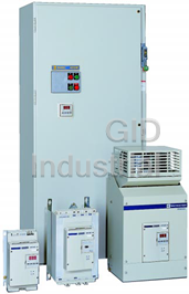
Schneider Electric ALTISTART 46 Series Open Style Soft Start Motor Controllers
Part Number
ALTISTART 46
Price
Request Quote
Manufacturer
SCHNEIDER ELECTRIC
Lead Time
Request Quote
Category
PRODUCTS - A
Datasheet
Schneider_Electric_ALTISTART_46_Soft_Start_Motor_Controller_datasheet1-610565104.pdf
1240 KiB

Extracted Text
® ALTISTART 46 Open Style Soft Start Motor Controllers Class 8636, 8638, 8639, and 8998 MCC’s CONTENTS Description . . . . . . . . . . . . . . . . . . . . . . . . . . . . . . . . . . . . . . . . . . . . . . . . . . . . .Page ATS46 Open Style Introduction . . . . . . . . . . . . . . . . . . . . . . . . . . . . . . . . . . . . . . . . . . . . . . . . . . . . . . . 3, 4 Applications . . . . . . . . . . . . . . . . . . . . . . . . . . . . . . . . . . . . . . . . . . . . . . . . . . . . . . . . 5 Product Characteristics. . . . . . . . . . . . . . . . . . . . . . . . . . . . . . . . . . . . . . . . . . . . . . . . 6 Protective Features. . . . . . . . . . . . . . . . . . . . . . . . . . . . . . . . . . . . . . . . . . . . . . . . . . . 7 Set-Up and Monitoring . . . . . . . . . . . . . . . . . . . . . . . . . . . . . . . . . . . . . . . . . . . . . 8-12 Dimensions . . . . . . . . . . . . . . . . . . . . . . . . . . . . . . . . . . . . . . . . . . . . . . . . . . . . . . . . 13 Component List for Recommended Wiring Diagrams. . . . . . . . . . . . . . . . . . . . . 14, 15 Wiring Diagrams for Recommended Applications . . . . . . . . . . . . . . . . . . . . . . . 16-18 Enclosed ATS46 Starters Technical Charateristics / Product Selection. . . . . . . . . . . . . . . . . . . . . . . . . . . . 20, 21 Factory Modifications (Optional) . . . . . . . . . . . . . . . . . . . . . . . . . . . . . . . . . . . . . 24, 25 Dimensions (Wall and Floor Mounts) . . . . . . . . . . . . . . . . . . . . . . . . . . . . . . . . . 26, 27 Model 6 Motor Control Centers . . . . . . . . . . . . . . . . . . . . . . . . . . . . . . . . . . . . 28-38 Application Considerations . . . . . . . . . . . . . . . . . . . . . . . . . . . . . . . . . . . . . . . . . . 39 Comparison of Reduced Voltage Starting Methods . . . . . . . . . . . . . . . . . . . . . . 40 Schneider Electric Brands Suggested Specifications . . . . . . . . . . . . . . . . . . . . . . . . . . . . . . . . . . . . . . . . . . . 41 ATS46 Open Style Soft Start Motor Controllers Introduction TM The ALTISTART 46 Soft Start with its TCS torque ramp control introduces digital based technology in soft starting and stopping of motor loads. The TCS torque ramp controls the motor accelerating/ decelerating torque based upon the configured acceleration/deceleration time and torque ramp settings. The ATS46 Soft Start still offers all the benefits of previous generation soft starts including: a. Reduction in motor inrush current upon starting to avoid utility peak demand charges b. Elimination of brown out conditions caused by across the line motor starting c. Reduction in motor starting torque to eliminate mechanic shock and stress caused by across the line motor starting ATS46D17N In addition, the ATS46 Soft Start now offers linear motor acceleration/deceleration. Applying TCS torque ramp control produces linear acceleration and deceleration ramps even when the motor is lightly loaded or oversized for the application. Linear acceleration and deceleration of the motor load make it possible to coordinate the ATS46 soft start and motor with the driven load to ensure trouble free applications. Easy to use-easy to configure for the following constant speed applications: Variable Torque Loads - Service Pumps, Booster Pumps, Circulating Pumps, Chiller Pumps, Exhaust Fans, Supply Fans High Inertia Loads - Compressors, Scrubber Fans, Induced Draft Fans, Centrifuges, Punch Presses, Band Saws, Wood Chippers, Ball Mills, Hammer Mills, Grinders, Crushers Constant Torque Loads - Screw Compressors, Conveyors, Aeration Blowers, Mixers, Flocculators, Belt Presses, Bottling Lines, Spindles, Lathes, Travel Drives, Agitators Feature / Benefits: Pump Loads - Eliminates Water-Hammer Coordination of check valves on pump loads is made easier by the TCS torque ramp control method of linearly controlling motor acceleration/deceleration torque. This allows the check valve to open or close gradually eliminating water-hammer on starting and stopping the pump. No starter options or external motor speed feedback devices are required. TCS torque ramp offers an infinite amount of acceleration/ deceleration profiles to fit any pump load combination. TCS torque ramp control acceleration and deceleration performance offers the maximum flexibility in soft-starter applications. High Inertia Loads - Optimizes accelerating torque during start-up reducing motor heat and accelerating current Previous technology designed soft starts accelerate high inertia loads in current limit. This produces a distorted NEMA B shaped speed torque profile. TCS torque ramp allows the motor to produce up to 100% rated torque at start and all the way through acceleration. This produces a constant accelerating torque for constant acceleration. The motor draws only the current required to produce the accelerating torque required. This results in lower accelerating current and a cooler start. Constant Torque Loads - Constant accelerating torque results in constant smooth load acceleration TCS torque ramp allows the motor to produce a constant torque during starting. Previous soft starts produce a changing accelerating motor torque profile. With the ATS46 the process will accelerate at a constant smooth rate using TCS torque ramp. Constant load acceleration keeps the product in position on a conveyor, threading material through a die, and prevents material from spilling or breaking during starting. 3 © 1997-2000 Schneider Electric All Rights Reserved 8/00 ATS46 Open Style Soft Start Motor Controllers Introduction Product Offering The ALTISTART 46 Soft Start open style product family includes 21 different power ratings from 17 to 1200 amps, each configurable for operation at 208, 230, 380, or 460 VAC at 50 or 60 Hz. These units are UL listed, CSA Certified and carry the CE mark. The ATS46 Soft Start is also available enclosed through 500 HP 460 VAC in factory pre-engineered configurations including: NEMA 1 or 12 non-combination stand-alone NEMA 12 combination stand-alone with shorting contactors as standard for units rated above 38 amps and offer reversing & full voltage bypass options MCC packaged starters in NEMA 1, 1A or 12 fusible disconnect combination style. Starter package includes as standard line isolation, shorting, and full voltage bypass contactor options. The stand-alone units are UL Listed and CSA Certified. The MCC packaged units are UL Listed. All open style starters include a starter mounted digital keypad for ease of user configuration and monitoring. All enclosed packages include a door mounted digital keypad. Comparison of TCS Torque Control Ramp Starting to Voltage/Current Limit Ramp Starting: The ALTISTART 46 Soft Start with its TCS torque ramp control starting applies the motor voltage based upon the motor torque developed. This allows for cooler motor acceleration and produces a constant acceleration torque for any given load allowing the motor to smoothly accelerate up to speed. The voltage/current limit style soft starts apply motor voltage based upon a voltage ramp or current limit setting. Either technique allows the motor to draw more current than necessary and produces a non- linear speed torque curve with varying acceleration torque. The amount of motor accelerating torque changes over the acceleration ramp producing a non-linear acceleration curve. ATS46 Soft Start with Soft Start Designs with TCS Torque Ramp Control Starting Combination Voltage Ramp/Curent Limit Starting Speed Speed Running Speed Running Speed Time Time Current Current Current Current Limit Limit Setting Setting Running Current Running Current Time Time Torque Torque Torque Setting Running Torque Running Torque Time Time 4 © 1997-2000 Schneider Electric All Rights Reserved 8/00 ATS46 Open Style Soft Start Motor Controllers Applications The Torque Control System of the ATS46 controller allows for flexibility of using soft start applications on a variety of machines which were traditionally not suited for reduced voltage starting. The ATS46 controller is easily adapted to both standard duty and heavy duty applications. The following table lists some suggested settings for several applications. This is to be used as a guide only—settings may vary depending on the actual application. Typical Typical Functions Performed Starting Type of Machine Duty Starting by the ATS46 Controller Current Time (secs) (In%) Ideal control for acceleration and deceleration (elimina- Centrifugal pump Standard tion of waterhammer). Protection against underload or 300 5 to 15 inversion of phase rotation. Positive displacement Standard Prevention of dry pump condition and reverse rotation. 350 5 to 10 pumps Standard Detection of overload caused by clogging or underload Ventilation fans (heavy if greater 300 10 to 40 (damaged transmission chain). than 30 s start) Cold compressor Standard Protection, even for special motors 300 5 to 10 Screw-type Protection against phase reversal. Contact for automat- Standard 300 3 to 20 compressor ic unloading at stop. Standard Protection against phase reversal. Contact for automat- Centrifugal compressor (heavy if greater 350 10 to 40 ic unloading at stop. than 30 s start) Positive displacement Protection against phase reversal. Contact for automat- Standard 350 5 to 10 compressor ic unloading at stop. Adjustable overload; detection of jammed material or of Conveyor Standard 300 3 to 10 underload for broken belt. Adjustable overload; detection of jamming or of under- Elevator Standard 350 5 to 10 load. Constant starting with variable load. Standard Circular saw, (heavy if greater Braking for fast stop. 300 10 to 60 band saw than 30 s start) Pulper, butchery knives Heavy Control of starting torque. 400 3 to 10 Agitator Standard Display of current & torque gives the material density. 350 5 to 20 Mixer Standard Display of current & torque gives the material density. 350 5 to 10 Braking to limit vibrations during stopping. Adjustable Grinder Heavy 450 5 to 60 overload and detection of jamming. Braking to limit vibrations during stopping. Adjustable Crusher Heavy 400 10 to 40 overload and detection of jamming. Refiner Standard Control of starting and stopping torque. 300 5 to 30 Press Heavy Braking to increase the number of cycles. 400 20 to 60 5 © 1997-2000 Schneider Electric All Rights Reserved 8/00 ATS46 Open Style Soft Start Motor Controllers Product Characteristics The ALTISTART 46 controller is supplied factory set and ready to use. By using the digital keypad or one of the optional communication modules, the factory settings, configuration, and display parameters can be modified. As shown in the figure to the left, the input and output of the controller consists of: • Digital keypad with LED display (3 / seven segment) • Status indicator (fault, power) • Removable terminal strips ALTISTART 46 soft-start/soft-stop units are recommended when the following features are required: • Limitation of supply voltage drop and reduction of current peaks during starting • Limitation of starting torque to protect the driven mechanism • Smooth acceleration and deceleration or braking to protect both equipment and personnel Digital Keypad LED Display Status • Gradual starting of high-inertia machines Indicators • Ability to easily adapt the starter for special machines Removable Terminal Strips • State-of-the-art motor protection The ALTISTART 46 controller can control motors with standard three-phase voltages between 208 and 500 V, and with power rating between 3 and 900 hp. Starting Characteristics The starting characteristics using TCS “torque ramp control starting” are shown in the graphs below. The acceleration ramp shows that by utilizing the ATS46 controller a linear acceleration ramp can be achieved without tachometer feedback — unlike traditional voltage ramp or current-limit soft starts, where motors are often sluggish at the beginning of the ramp and over-accelerate at the end of the ramp. By controlling the development of the motor’s torque, TCS “torque ramp control starting” also requires less current than when using traditional current-limiting soft starts. As shown in the graph below, the TCS ramp can result in as much as 15% less current draw than a traditional current-limiting soft start. Acceleration Ramp Starting Current Limit N = f(t) ATS46 ramp Traditional soft starts ATS46 Traditional soft starts t (Time) t (Time) A full-voltage start may also be obtained by increasing the current limit to the maximum setting and decreasing the ramp time to zero. The initial torque may be adjusted up to 100% of the motor nominal torque to assist in duplicating motor performance at full voltage. Stopping Characteristics TM The selection of freewheel stop, deceleration ramp, or INTELE braking is standard on all ATS46 con- trollers. The freewheel stop time (t1) is a function of the inertia and resistive torque of the application. When using the deceleration ramp, the stopping time (t2) will be longer than the freewheel stop time (t1). By controlling the deceleration ramp based on the motor torque, the ATS46 controller can eliminate wa- terhammer without requiring a special “pump version” starter. 6 © 1997-2000 Schneider Electric All Rights Reserved 8/00 N (Speed) Id (Current) ATS46 Open Style Soft Start Motor Controllers Protective Features When using INTELE braking, the stop time (t3) will be less than the freewheel stopping time (t1). INTELE braking is a two-part braking which does not require external components. It produces less motor heating than traditional DC injection braking. The graphs shown below compare the performance of the deceleration ramp and INTELE braking. INTELE Braking is best utilized provided all of the criteria is met: • 4 pole or 6 pole motors only • Motor slip less than or equal to 3% 2 t (sec) = WK x srpm 308 x (T X 0.40) FLT where: t (sec) = Calculated value must be equal to or less than 40 2 2 WK = Connected motor load inertia (lb-ft ) srpm = Change in rpm or synchronous speed T = Full Load Torque (lb-ft) FLT Deceleration Ramp INTELE Braking or N (Speed) N (Speed) I (Current) I (Current) t t (Time) t2 > t1 tb ti t3 < t1 Protective Features The ATS46 controller provides state-of-the-art protection for motor and starter. The motor and starter status are continuously monitored even if a shorting contactor is used. User-adjustable overload protec- tion is available with a pre-alarm, which can be used to signal a change in the process before an over- load condition actually occurs. Phase loss protection is always present with a 500 millisecond delay to prevent nuisance tripping resulting from normal power disturbances. The following additional features are available and can be set-up using the keypad or communications module: • Phase reversal protection — Upon a start command, the rotation of the mains phases is checked to prevent the motor from running in the reverse direction. • Stall protection — A maximum starting time can be set to prevent a thermal overload if the motor is stalled during start-up. The maximum starting time can be adjusted from 10 to 999 seconds. • Jam protection — For protection against material jams or unexpected loading, an overcurrent level can be set to signal a fault condition before the motor is actually overloaded. The overcurrent level can be adjusted from 50% to 300% of the motor nominal current. • Underload protection — For indication of an unexpected loss in motor loading, such as might occur with a broken belt or a dry pump. The underload level can be adjusted based on the normal running torque for maximum application flexibility. The ATS46 controller may be set up for automatic fault reset. This allows the controller to re-start after a nuisance trip if the fault has cleared. In addition, a special test mode is available for commissioning a high-horsepower controller using a low-horsepower, unloaded motor. Thermal Overload Protection A microprocessor-controlled surveillance system continuously monitors the temperature rise of the mo- tor and of the starter unit. Calculations are based on the motor operating current measured by the con- troller as compared to the nominal current setting. The thermal state of the motor and controller are stored even when control power is lost. A logic output pre-alarm indicates that the motor has exceeded its nominal temperature rise threshold before an overload occurs. After a stoppage due to a thermal fault, the control circuit prevents restarting if the temperature of the motor is still too high. You may configure the available logic input to require op- erator acknowledgment of a thermal overload to reset the controller. 7 © 1997-2000 Schneider Electric All Rights Reserved 8/00 ATS46 Open Style Soft Start Motor Controllers Set-Up and Monitoring The ATS46 controller is factory preset to provide class 10 overload protection for standard duty applica- tions, but can be adapted for other starting classes (2, 10A, 15, 20, 25, or 30). The table below shows the tripping time according to starting class. [1] Starting Class Tripping Time at 7.2 In Tripping Time at 3 In 2 1.5 s 9 s 10A 3.7 s 22 s 10 7.4 s 45 s 15 11.1 s 67 s 20 14.8 s 89 s 25 18.5 s 112 s 30 22.2 s 134 s [1] Conforming to IEC 947-4-1 The factory setting is as follows: • Class 10 for standard service • Class 20 for heavy duty Standard duty for the starter unit is one which does not exceed 230 seconds at 3 times the motor nominal current per hour, or 6.3% of operating time including starting, stopping, or braking. For example, within one hour, the ATS46 controller could perform: • 38 starts of 6 sec. or 10 starts of 23 sec. • 19 starts of 6 sec. and 19 decelerated or braked stops of 6 sec. • 5 starts of 23 sec. and 5 decelerated or braked stops of 23 sec. Above these levels, or when the motor connected load inertia is greater than ten times the motor rotor inertia, the controller should be sized for heavy-duty operation. Set-Up and Monitoring The ATS46 controller is factory preset, which, for many applications, allows operation without requiring adjustment. As shown in the figure below, a switch is located behind the removable display module that can be toggled from standard-duty to heavy-duty application presets. 1 2 1 = Standard Duty 2 = Heavy Duty The ATS46 controller is factory preset to standard duty operation. To switch the factory presets for heavy duty applications, remove the keypad and change the selector switch to position 2, as shown in the inset of the figure above. For the change to take affect, control power must be cycled after adjusting the se- lector switch. The following factory presets change when adjusting the selector switch from position 1 to position 2: Parameter Standard-Duty Preset Heavy-Duty Preset Acceleration Ramp AC 10 seconds 15 seconds Current Limit Ilt 300% 350% Overload Protection thp Class 10 Class 20 8 © 1997-2000 Schneider Electric All Rights Reserved 8/00 ATS46 Open Style Soft Start Motor Controllers Set-Up and Monitoring The factory preset for the motor nominal current, I , and corresponding motor combinations for standard- n duty and heavy-duty presets are listed in the table below. If the motor full load amp rating is not between 95% and 105% of the ATS46 controllers factory preset value, or if using a 1.0 service factor motor, the nominal current setting for the motor should be adjusted for optimal motor protection and performance. Standard-Duty Applications Heavy-Duty Applications Rated Current Preset Motor Preset Motor ATS46 Model Motor Power Rating Motor Power Rating f Current Current I I 208V 230V 460V I 208V 230V 460V CL n n ATS46D17N 17 15.2 3 5 10 12 2 3 7.5 ATS46D22N 22 21 5 7.5 15 15.2 3 5 10 ATS46D32N 32 28 7.5 10 20 21 5 7.5 15 ATS46D38N 38 34 10 — 25 28 7.5 10 20 ATS46D47N 47 42 — 15 30 34 10 — 25 ATS46D62N 62 54 15 20 40 42 — 15 30 ATS46D75N 75 68 20 25 505415 20 40 ATS46D88N 88 80 25 30 606820 25 50 ATS46C11N 110 98 30 40 75 80 25 30 60 ATS46C14N 145 128 40 50 100 98 30 40 75 ATS46C17N 176 160 50 60 125 128 40 50 100 ATS46C21N 210 190 60 75 150 160 50 60 125 ATS46C25N 257 236 75 100 200 190 60 75 150 ATS46C32N 320 290 100 125 250 236 75 100 200 ATS46C41N 410 367 125 150 300 290 100 125 250 ATS46C48N 480 430 150 — 350 367 125 150 300 ATS46C59N 590 547 — 200 400 430 150 — 350 ATS46C66N 660 610 200 250 500 547 — 200 400 ATS46C79N 790 725 250 300 600 610 200 250 500 ATS46M10N 1000 880 350 400 800 725 250 300 600 ATS46M12N 1200 1130 400 450 900 880 350 400 800 f At 40° C ambient. Note: If purchasing a Class 8636, 8638 or 8639 Enclosed Starter, modifications may have been made to the factory settings listed above to more closely match the motor full load amp ratings at the specified motor volt- age. In addition, if an input contactor is provided, the R1 relay has been reset for isolation contactor control. Keypad Use A keypad is provided to allow digital setup of the controller and real-time indication of motor performance. The keypad has three seven-segment display characters, one program LED, and four pushbuttons for programming the controller, as shown in the figure to the left. The keypad is removed by loosening the holding screw, and may be removed while the controller is switched on. The keypad is not required to be in place to operate the controller. The adjustable parameters are separated into 3 levels. Two switches on the back of the display keypad may be adjusted to provide access to all three programming levels or prevent adjustment to the controller. To avoid accidental controller modifications, the controller is preset to prevent adjustment without first re- moving the keypad and changing the DIP switch setting . 888 Program LED Holding Screw PROG DATA PROG Data Pushbutton Scroll Forward Pushbutton Program Pushbutton Scroll Backward Pushbutton 9 © 1997-2000 Schneider Electric All Rights Reserved 8/00 ATS46 Open Style Soft Start Motor Controllers Set-Up and Monitoring Adjustment Capabilities Tables show adjustment parameters if Level 1 is selected; usually selected for simple applications. Level 1 Adjustment and Configuration Parameters Adjustment Range In Motor nominal current (in A) 50 to 130% ILt Motor limit current (in A) 150 to 500% Acc Torque ramp on acceleration (in s) 1 to 60 seconds dEc Torque ramp on deceleration (in s) 1 to 60 seconds StY Stopping type (freewheel, ramp, braking) f – b – d Threshold to change to freewheel stopping at the end of the deceleration ramp Edc 0 to 100% (percentage of Tn) brc Braking torque level (as a percentage) 0 to 100% In addition to the Level 1 parameters shown above, the following parameters may be adjusted in Level 2. Level 2 Adjustment and Configuration Parameters Adjustment Range bSt Voltage boost (as a percentage of V) 50 to 100% tqo Initial starting torque (as a percentage of Tn) 0 to 100% tLI Maximum torque limit (as a percentage of Tn) 10 to 200% ULL Underload threshold (as a percentage of Tn) 20 to 100% tLS Maximum start time (in s) 10 to 999 s thp Motor thermal protection (choice of classes) Off, 10, 10A, 15, 20, 25, 30 The following table shows the adjustment and monitoring parameters if Level 3 is selected (which allows the factory configuration to be modified). Level 3 Parameters Which Can Be Configured ArS Automatic restart rth Reset motor thermal state CLp Torque control Int Return to factory settings LSc Stator loss compensation (as a %) SSt Test on low power motor O-4 Signal type in AO1 CSc Cascade starting LI Assignment of LI tFr Operating time since reset (in hours) Lo1 Assignment of LO1 EbA Adjustment of braking (as a %) OIL Current tripping threshold (as a percentage of In) Ao Assignment of analogue output AO1 Phr Phase rotation fault ASc Scale AO rI Assignment of relay R1 This level is independent of Levels 1 and 2. When Level 3 is selected, the user does not have access to the parameters of Levels 1 and 2, but can reconfigure the basic product. If the locking level is selected, only the monitoring parameters and Level 1 and 2 parameters can be read; no parameters can be modified. Monitoring Capabilities The following parameters may be monitored when in lockout mode or Level 1 or 2 programming levels. Monitoring Parameters (displayed while the ATS46 is running) CoS Value of cos ϕ (power factor) Lth Motor thermal state (as a percentage) Ltr Load status (as a percentage of Tn) Lcr Motor current (in A) rdY Starter status In addition to monitoring the operational status of the motor, the following fault codes are available to simplify troubleshooting the application. Fault Definitions Code Description Code Description O c F Overcurrent fault O h F Starter thermal fault I n F Internal failure fault L r F Locked rotor fault P i F Phase inversion fault U L F Motor underload P h F Phase fault S t F Maximum start time exceeded F r F Frequency fault E T F External fault U S F Supply fault S L F Serial link fault [1] O L F Motor thermal fault 1. If LI is configured for motor overload reset (Llt), operator acknowledgment of the overload condition is required. The overload must also be reset through the logic input after the fault has cleared before restarting the motor. 10 © 1997-2000 Schneider Electric All Rights Reserved 8/00 ATS46 Open Style Soft Start Motor Controllers Set-Up and Monitoring Option Modules The following option modules may be used to display parameters and modify the factory settings. The modules are used in place of the display keypad, and are the same for all ATS46 soft start models. Description Reference Weight (kg) [1] Remote mounting kit VW3G46103 0.500 ® Communication option for UNITELWAY™, MODBUS RTU/Jbus, MODBUS VW3G46301 0.500 [2] ASCII protocols [1] Kit comprising a unit which plugs into the front panel of the ATS46 controller, a connection (3 meters long) and a flush-mounting kit. To be used with keypad provided with controller. PLC Communication [2] Option kit includes a unit which plugs into the front panel of the ATS46 controller and a connection cable (3 meters long) Module (VW3G46301) General Characteristics The asynchronous motor associated with the ATS46 controller must be capable of starting the load to be driven when it is supplied with reduced voltage. The products are defined for normal or heavy duty. In cases of heavy duty, check with the motor manu- facturer that any derating is compatible with the operating cycle and the starting times. This will avoid trip- ping the thermal overload protection integrated within the ATS46 controller, which may result from abnormal rises in the motor temperature. Environmental Characteristics The electronic soft-start/soft-stop units were developed and performance-tested in accordance Conformity to standards with the following international standards and recommendations relating to industrial control gear (IEC, NFC, VDE), IEC 947-4-2, UL, and CSA. The products have CE marking in accordance with the low voltage and electromagnetic compat- Marking ibility directives. NEMA: Open devices Starters ATS-46D17N to 46C14N Degree of protection IEC: IP 20 (IP 10 when no connections are present) Starters ATS-46C17N to 46M12N IP 00 Conforming to IEC 68-2-27 Shock resistance 15 g for 11ms Starters ATS-46D17N to 46D38N Conforming to IEC 68-2-6, Vibration resistance NFC 2076 and BV1 0 to +40°C without derating (between +40°C and +60°C derate the ALTISTART Soft Start current For operation by 1.2% for each degree C) Ambient air temperature For storage -25 to +70°C Maximum relative humidity Conforming to IEC 68-2-3 93% without condensation or dripping water Maximum ambient Conforming to IEC 664 Degree 3 pollution Maximum operating 1000m without derating (above this, derate the ATS46 controller current by 0.5% for each addi- tional 100m) altitude [1] 15° 15° Operating Position Permanent maximum angle in relation to the normal vertical mounting position 1. In certain (marine) applications, the starter can temporarily tolerate an angle of ±45° in relation to the vertical 11 © 1997-2000 Schneider Electric All Rights Reserved 8/00 ATS46 Open Style Soft Start Motor Controllers Set-Up and Monitoring Electrical Characteristics Category of use Conforming to IEC 947-4-2 AC-53a 208V – 10%...240V + 10% 3-phase supply voltage 380V – 15%...415V + 10% 440V – 15%...500V + 10% 50 or 60 Hz, self-adapting Frequency ±5% while starting, +5/-15% while running Nominal current 17...1200A in 21 ratings Motor power 2 to 900 hp 208V...240V Voltage indicated on the 380V...415V motor rating plate 440V...500V The motor nominal current is adjustable from 0.5 to 1.3 times the product rating, and Current adjustment the maximum starting current may be adjusted from 1.5 to 5 times the product rating Factory setting: 3 times the nominal current for standard duty on a torque ramp of 10s, Starting method adjustable from 0.5 to 60 seconds Freewheel “Freewheel” stop by default Method of stopping Controlled by torque ramp Adjustable from 0.5 to 60 seconds Braked stop Automatically controlled by the load inertia Locking (red) On indicates fault; flashing indicates automatic reset LED Display Supply on (green) On indicates supply on Fault Relay (can be assigned for control of an isola- R1: 1 N.O. & 1 N.C. tion contactor) End of Start Relay R2: 1 N.O. Maximum operating power Inrush 1200VA, maintained 120VA Output relays (2 relays) Minimum switching capacity 100 mA@ 24V Nominal operating current 0.5A. Categories AC-14, AC-15 (@ 240V), and DC-13 (@ 48V) Nominal thermal current 5A Maximum operating voltage 400V Mechanical durability 50 million operating cycles Indication of motor current, torque, ther- Current output 0-20mA with 500 ohm impedance; can be Analog output AO mal state, or power factor. reassigned to 4-20mA. Precision ± 3%, linearity ± 3% LO1 (indication of thermal pre-alarm or Maximum voltage 40V, minimum voltage 10V motor powered) Logic outputs LO Maximum output current 200mA LO2 (excess current alarm) 1 isolated output + 24V (PL) Available internal power supply Precision +/- 20% Maximum 100 mA Force to freewheel, external fault, reset of 3 logic inputs with 3.5 kohm impedance Logic inputs LI thermal overload, local control, or cas- Power supply + 24V cade State 0 if < 5V; State 1 if > 11V Integrated thermal protection for motor and starter unit Mains supply protection Phase failure and imbalance indicated by output relay Protection Thermocontacts On fan-cooled units, 75 to 1200A ratings The ATS46 controller must be selected according to the nominal power of the motor and the duty required. Any starter can be used for standard or heavy duty. For heavy Selection of starter unit duty, derate the starter by one nominal motor size. The ATS46 controller can be used for heavy duty applications at the standard duty rating if the product is bypassed at the end of starting. 12 © 1997-2000 Schneider Electric All Rights Reserved 8/00 ATS46 Open Style Soft Start Motor Controllers Dimensions ATS46 D47N to C14N ATS46 D17N to D38N Installation 6.0" Precautions for All ATS46 Soft Start * Models When fitting the ATS46 controller, allow a mini- mum of 4” above and below the unit, and 2” to the left and right of the unit. 2.1" 4.4" 0.4" 8.3" 0.4" c 9.4" * c 0.4" 5.9" 0.4" 4" 6.7" *Removable earth boss, supplied with the 2" 2" ATS46 C17N to C32N product but not fitted 4" ATS46 bc h Model Install the ATS46 con- D17N 12.8" 5.9" 8.3" troller vertically. D22N 12.8" 5.9" 8.3" Avoid placing the D32N 14.8" 5.9" 10.2" ATS46 controller close D38N 14.8" 5.9" 10.2" to or above heating D47N 13.0" 6.6" 11.8" elements. D62N 13.0" 6.6" 11.8" D75N 13.4" 9.6" 11.8" D88N 13.4" 9.6" 11.8" C11N 15.4" 9.6" 13.8" 10.6" 13.3" C14N 17.3" 9.6" 15.7" 14.3" 14.7" ATS46 C41N to C66N ATS46 C79N to M12N 15.8" 4xŞ0.4" 0.4" 0.4" 30.2" 0.4" 13.9" 13.2" 13.9" 27.8" 0.4" 4xŞ0.4" 8.8" 8.4" 1" 1" 1" 4.1" A1 A1 B1 B1 C1 A2 C1 13 5 1 A2 1 B2 2 1 3 5 3 B2 2 3 C2 4 5 5 C2 4 6 6 Ş0.6" 0.2" 0.2" 1.8" 3.3" Ş0.3" 0.2" 0.2" 4.8" 1" 1" 1" 6.4" 4.6" 4.6" 4.8" 8.1" 8.8" 6.6" 7.9" 10.0" 1.6" 4.6" 4.6" 2.5" 11.5" 13 © 1997-2000 Schneider Electric All Rights Reserved 8/00 1.4" b 0.6" 31.5" 4.4" 37.4" h 0.6" 1" b 31.5" 4.4" 37.4" 0.4" 19.7" 6.0" 39.8" h 0.6" 27.0" ATS46 Open Style Soft Start Motor Controllers Component List for Recommended Wiring Diagrams Suggested Components for Standard Duty Applications. Induction Motor ALTISTART Controller M ATS FU1/FU2 Device Rated Rated hp [1] ATS46 Soft Start ATS Control Class CC Control Fuse Size Current 208 V 230 V 460 V Model @ 40 °C [2] Power Burden @ 208/230 V @ 460 V 3 5 10 ATS46 D17N 17 20 VA 0.25 A 0.25 A 5 7.5 15 ATS46 D22N 22 20 VA 0.25 A 0.25 A 7.5 10 20 ATS46 D32N 32 20 VA 0.25 A 0.25 A 10 — 25 ATS46 D38N 38 20 VA 0.25 A 0.25 A — 15 30 ATS46 D47N 47 70 VA 0.5 A 0.25 A 15 20 40 ATS46 D62N 62 70 VA 0.5 A 0.25 A 20 25 50 ATS46 D75N 75 70 VA 0.5 A 0.25 A 25 30 60 ATS46 D88N 88 70 VA 0.5 A 0.25 A 30 40 75 ATS46 C11N 110 70 VA 0.5 A 0.25 A 40 50 100 ATS46 C14N 145 70 VA 0.5 A 0.25 A 50 60 125 ATS46 C17N 176 250 VA 1.6 A 0.8 A 60 75 150 ATS46 C21N 210 250 VA 1.6 A 0.8 A 75 100 200 ATS46 C25N 257 250 VA 1.6 A 0.8 A 100 125 250 ATS46 C32N 320 250 VA 1.6 A 0.8 A 125 150 300 ATS46 C41N 410 350 VA 1.6 A 0.8 A 150 — 350 ATS46 C48N 480 350 VA 1.6 A 0.8 A — 200 400 ATS46 C59N 590 350 VA 1.6 A 0.8 A 200 250 500 ATS46 C66N 660 350 VA 1.6 A 0.8 A 250 300 600 ATS46 C79N 790 500 VA 3.0 A 1.5 A 300 400 800 ATS46 M10N 1000 500 VA 3.0 A 1.5 A 400 450 900 ATS46 M12N 1200 500 VA 3.0 A 1.5 A To select control operators (push buttons, pilot lamps, and selector switches), control power transformers, and wire management devices (control and power terminal strips, wire terminations) indicated on the referenced control circuit configurations, refer to the latest editions of Square D’s full line product catalogs. Notes: 1. Motor full load currents through 500 hp @ 460 V and 250 hp @ 230 V are taken from UL508 Table 54.2 (NFPA 70, Table 430-150). Above 500 hp @ 460 V and 250 hp @ 230 V, motor full load currents are calculated based upon 1.2 A/hp for 460 V and 2.4 A/hp for 230 V. Motors listed are for standard duty applications. For heavy duty applications, select the next larger controller size. 2. The ambient temperature indicated in the table represents the temperature of the air surrounding the ALTISTART controller. Any additional temperature factors associated with the enclosure system or actual installation ambient temperature must be considered when determining the actual rated current (I ) of the starter. For operating ambient above 40 °C but not exceeding 60 °C, the rated current (I ) of the starter CL CL must be de-rated by 1.2% per °C. 14 © 1997-2000 Schneider Electric All Rights Reserved 8/00 ATS46 Open Style Soft Start Motor Controllers Component List for Recommended Wiring Diagrams ATS Contactors [3, 4, 7] Disconnect [10] KM1 KM2 KM3 Fusible Disconnect Circuit Breaker ATS46 Isolation Reversing Mechanical Shorting Power Fuses Molded Case Thermal Model Contactor Contactor [5] Interlock Contactor Class/Rating Fuse Block [8] Switch [9] Magnetic [9] D17N LC1 D1211G6 LC1 D1211G6 [6] N/A RK5 / 20 A 9080 FB3611R FHL36000M FAL34030 D22N LC1 D1811G6 LC1 D1811G6 [6] N/A RK5 / 30 A 9080 FB3611R FHL36000M FAL36040 D32N LC1 D3211G6 LC1 D3211G6 [6] N/A RK5 / 40 A 9080 FB3621R FHL36000M FAL34050 D38N LC1 D3211G6 LC1 D3211G6 [6] N/A RK5 / 45 A 9080 FB3621R FHL36000M FAL34060 D47N LC1 D4011G6 LC1 D4011G6 [6] LC1 D4011G6 RK5 / 60 A 9080 FB3621R FHL36000M FAL34080 D62N LC1 D5011G6 LC1 D5011G6 [6] LC1 D5011G6 RK5 / 70 A 9080 FB3631R FHL36000M FAL34090 D75N LC1 D6511G6 LC1 D6511G6 [6] LC1 D6511G6 RK5 / 90 A 9080 FB3631R FHL36000M FAL34100 D88N LC1 D8011G6 LC1 D8011G6 [6] LC1 D8011G6 RK5 / 110 A 6R200A3BE FHL36000M KAL36110 C11N LC1 D8011G6 LC1 D8011G6 [6] LC1 D8011G6 RK5 / 150 A 6R200A3BE KHL36000M KAL36150 C14N LC1 F150G6 LC1 F150G6 LA9 FF970 LC1 F150G6 RK5 / 175 A 6R200A3BE KHL36000M KAL36200 C17N LC1 F150G6 LC1 F150G6 LA9 FF970 LC1 F150G6 RK5 / 200 A 6R200A3BE KHL36000M LAL36225 C21N LC1 F185G6 LC1 F185G6 LA9 FG970 LC1 F185G6 RK5 / 250 A 6R400A3B KHL36000M LAL36250 C25N LC1 F265G7 LC1 F265G7 LA9 FJ970 LC1 F265G7 RK5 / 350 A 6R400A3B LHL36000M LAL36350 C32N LC1 F330G7 LC1 F330G7 LA9 FJ970 LC1 F330G7 RK5 / 400 A 6R400A3B LHL36000M LAL36400 C41N LC1 F400F7 LC1 F400F7 LA9 FJ970 LC1 F400F7 RK5 / 500 A 6R600A3B LHL36000M MAL36600 C48N LC1 F400F7 LC1 F400F7 LA9 FJ970 LC1 F400F7 RK5 / 600 A 6R600A3B MHL360006M MAL36600 C59N LC1 F500F7 LC1 F500F7 LA9 FJ970 LC1 F500F7 L / 650 A [8] MHL360008M MAL36800 C66N LC1 F500F7 LC1 F500F7 LA9 FJ970 LC1 F500F7 L / 800 A [8] MHL360008M MAL36900 C79N LC1 F630F7 LC1 F630F7 LA9 FL970 LC1 F630F7 L / 1000 A [8] MHL36000M [11] M10N LC1 F630F7 LC1 F630F7 LA9 FL970 LC1 F630F7 L / 1100 A [8] MHL36000M [11] M12N LC1 F780F7 LC1 F780F7 LA9 FX970 LC1 F780F7 L / 1600 A [8] NCL3600012M [11] Notes: 3. All coils are selected for 120 V, 60 Hz operation. Refer to the Digest for additional coil voltages or auxiliary contact configurations. One block may be added to each contactor. 4. Power terminals are not included with LC1-F contactors. Refer to the latest editions of Square D’s full line product catalogs for additional or- dering information. 5. Reversing contactors for C11 through M12 controllers must be assembled from components. Parts quantities for a basic contactor assembly, minus the power connection links and terminals, are indicated before each part number. Refer to the latest editions of Square D’s full line product catalogs for power connector link and terminal kits. Reversing contactor interlock units used for the C79 through M12 controllers are designed for vertical interlocking of the individual contactors. Horizontally interlocked contactors are used for D17 through C59 controllers. 6. The “D” Line Contactor is available as a reversing configuration. For these applications, change the KM1 part number prefix from LC1- to LC2- to order the KM1 and KM2 combination complete with mechanical interlocks. 7. The use of transient suppressors across all contactor coils is recommended. Refer to the latest editions of Square D’s full line product catalogs for selection of transient suppressors. 8. Fuse holders listed are for Class R fuses only. Fuse blocks recommended for use with ATS46 soft start models D88 through C48 are Bussmann part numbers. Class L fuses require bolt-on connections to user-supplied power bus work. 9. The molded case switches and circuit breakers selected require the addition of operator mechanisms to allow operation from the exterior of an enclosure. Refer to the latest editions of Square D’s full line product catalogs for operator mechanism information. When using a shunt trip relay for SCR fault isolation, order a disconnect switch with suffix -1021 for addition of shunt trip coil. 10. According to the National Electric Code, branch circuit overcurrent protection must be provided for each controller. Short circuit protective devices recommended in this table are within NEC requirements for Type 1 coordination. 11. Devices rated above 660 A have not been coordinated with circuit breakers. Must use Class L fuse for overcurrent protection with ATS46 soft start models C79, M10, and M12N. 15 © 1997-2000 Schneider Electric All Rights Reserved 8/00 ATS46 Open Style Soft Start Motor Controllers Wiring Diagrams for Recommended Applications Non-Reversing with Shunt Trip Fault Isolation L1 L2 L3 Circuit Breaker* w/Shunt Trip Coil* 1 3 Ground Fault C/T* 5 Relay (GFR)* 2 7 FU1 FU2 1 1 T1 C A1 B1 C1 1/L1 3/L2 5/L3 500V 120V 3 KM3 KM3 KM3 * FAULT 2 R1D R1B TYPICAL TRIP TR* POWER SOLID STATE RELAY OVERLOAD RELAY POLE 4 A2 B2 C2 TS1 2/T1 4/T2 6/T3 STOP RUN LI PL TR CB SHUNT ST* TRIP COIL* STOP START (2 SEC) RUN G* OR M MOTOR FAULT GFR 6 THERMAL SW SEE (R1C R1A RUN COMMAND BELOW RCR* RELAY (A) (B) 4 5 OFF ON (C) TS1 1 Control circuit connected for 460 V operation. RCR Reconnect as required for other voltages. END 2 Shorting contactor terminals not provided START UP OR 7 SHORTING on D17, D22, D32 OR D38 controllers. R2A R2C CONTACTOR KM3A* 3 For shorting contactor operation with D47N PILOT RELAY 4 through M12N controllers, add KM3 with associated control circuit. TS1 7 RCR KM3A 3 4 Relay contact located on ATS controller. SHORTING KM3* CONTACTOR Located at motor. Jumper if switch not present. 5 TS4 6 Use RCR relay logic for ATS 2-wire or 3-wire control when using shorting contactor. POWER ON R* 7 For D47 through C11 controllers using a shorting contactor, * = User supplied pilot relay KM3A is not required. Substitute coil of KM3 contactor in place of KM3A pilot relay. 2-WIRE CONTROL W / O AUTO 2-WIRE CONTROL W / AUTO 3-WIRE CONTROL OFF OFF ON HAND AUTO STOP START (B) (A) (B) (A) USER (A) (B) SUPPLIED (C) 16 © 1997-2000 Schneider Electric All Rights Reserved 8/00 ATS46 Open Style Soft Start Motor Controllers Wiring Diagrams for Recommended Applications Non-Reversing with Isolation Contactor L1 L2 L3 SW* FU3 FU4 FU5* FU1 FU2 KM1* KM1 KM1 1 T1 1 A1 B1 C1 1/L1 3/L2 5/L3 C 500V 120V 3 KM3 KM3 KM3* 2 MOTOR TYPICAL THERMAL SW SEE RUN COMMAND POWER SOLID STATE RCR* BELOW RELAY POLE OVERLOAD RELAY (A) (B) 5 (C) A2 B2 C2 LI 2/T1 4/T2 6/T3 STOP RUN PL TS1 RCR FAULT RCR R1A R1C FAULT FR* RELAY 4 TS1 M FR RCR ISOLATION KM1* CONTACTOR TS2 7 1 Control circuit connected for 460 V operation. Reconnect as required for other voltages. END START UP SHORTING 6 2 Shorting contactor terminals not provided on D17, D22, R2A R2C CONTACTOR D32 or D38 controllers. KM3A* PILOT RELAY 4 For optional shorting contactor operation with D47N through M12N 3 TS1 controllers, add KM3 with associated control circuit. KM3A 6 SHORTING KM3* CONTACTOR 4 Relay contact located on ATS controller. TS4 5 Located at motor. Jumper if switch not present. POWER ON R* For D47 through C11 controllers using a shorting contactor, 6 pilot relay KM3A is not required. Substitute coil of KM3 contactor in place of KM3A pilot relay. FR FAULT W* Set RCR time slightly longer than the expected deceleration 7 time from rated speed to zero speed. The time delay RCR contact may be omitted if the configuration of the R1 relay is changed to isolation KM1 contactor control. RUN G* 2-WIRE CONTROL W / O AUTO 3-WIRE CONTROL 2-WIRE CONTROL W / AUTO * = User supplied OFF ON OFF HAND AUTO STOP START (B) (A) (B) (A) USER (A) (B) SUPPLIED (C) 17 © 1997-2000 Schneider Electric All Rights Reserved 8/00 ATS46 Open Style Soft Start Motor Controllers Wiring Diagrams for Recommended Applications Reversing with Isolation Contactors L1 L2 L3 SW* FU3 FU4 FU5* 1 T1 120V KM2* KM2 KM2 KM1* KM1 KM1 FU1 FU2 MOTOR THERMAL SW (B) RRR RUN FWD RFR* RELAY (A) (A) SEE (C) 5 RFR BELOW TS1 1 (D) RFR RUN REV A1 B1 C1 3/L2 5/L3 C 500V 1/L1 RRR* RELAY 6 (E) KM3 KM3 KM3 RRR TS1 * ATS 2 FAULT (27) (28) FAULT TYPICAL FR* RELAY POWER SOLID STATE 4 OVERLOAD RELAY POLE TS1 A2 B2 C2 2/T1 4/T2 6/T3 STOP RUN LI PL FR RFR 7 KM2 FORWARD KM1* CONTACTOR TS2 RRR KM1 RRR 8 KM1 REVERSING KM2* CONTACTOR RFR KM2 M TS2 END START UP 6 12 SHORTING (43) (44) 1 Control circuit connected for 460 V operation. KM3A* CONTACTOR Reconnect as required for other voltages. PILOT RELAY 4 TS1 TS1 2 Shorting contactor terminals not provided on D17, D22, D32, KM3A 6 12 or D38 controllers. SHORTING KM3* CONTACTOR 3 For shorting contactor operation with D47 through M12N controllers, add KM3 with associated control circuit. TS4 4 Relay contact located on ATS controller. POWER ON R* Located at motor. Jumper if switch not present. 5 FR For D47 through C11 controllers using a shorting contactor, 6 FAULT pilot relay KM3A is not required. Substitute coil of KM3 contactor W* in place of KM3A pilot relay. KM1 Set RFR time slightly longer than the expected deceleration 7 RUN FORWARD G* time from rated forward speed to zero speed. Set RRR time slightly longer than the expected deceleration 8 KM2 time from rated reverse speed to zero speed. RUN REVERSE A* 9 Remove these contacts to inhibit direction reversal without * = User supplied first depressing STOP pushbutton. 2-WIRE CONTROL W / AUTO START AUTO DIRECTION 3-WIRE CONTROL 2-WIRE CONTROL W / AUTO START MANUAL DIRECTION 2-WIRE CONTROL W / O AUTO RUN OFF OFF RUN OFF STOP FWD HAND AUTO FWD REV FWD REV REV HAND AUTO FWD REV (B) (B) (B) (B) (A) (A) (A) (A) F R 9 (C) (D) USER SUPPLIED (D) USER SUPPLIED R F (D) 9 (E) USER SUPPLIED (D) 18 © 1997-2000 Schneider Electric All Rights Reserved 8/00 Enclosed ATS46 Starters Enclosed ATS46 soft starters follow the recommended wiring diagrams shown on pages 16 through 18 to provide automatic SCR fault isolation. On non-combination controllers, the disconnect must be sup- plied separately, and must not exceed the maximum fuse or thermal magnetic circuit breaker size listed on page 15. If an isolation contactor is not specified, the shunt trip relay must be tied into the external disconnect mechanism on non-combination starters to maintain the recommended level of SCR fault isolation. Enclosed devices with a heavy duty rating utilize the next larger ALTISTART controller model, and are coordinated for larger overcurrent protective devices as required to obtain longer starting times. The fault relay on enclosed units with isolation contactor (that is, type ***N) is pre-programmed for con- trol of an isolation contactor. In this configuration, the R1 relay changes state upon a start command, and switches back if a fault is detected or after deceleration (if selected) is complete. This provides iso- lation of the soft starter and motor in a fault condition and when the motor is off. Enclosed ATS46 Starters Catalog Number Identification Catalog numbers for enclosed ATS46 soft starters may be interpreted using the following information: For Modifications Type Number See pages 24 and 25 8636 N L A 4 S - X X X X Class Configuration 8636 Non-combination S = Nonreversing with shunt trip disconnect 8638 With fusible disconnect N = Nonreversing with isolation contactor 8639 With circuit breaker R = Reversing with isolation contactors Duty Rating N = Normal start (standard duty) L = Long start (heavy duty) Voltage Code Controller Amp Rating 8 = 208 D = 15.2 N = 156 2 = 230 E = 22 O = 192 4 = 460 F = 28 P = 248 H = 42 Q = 312 I = 54 R = 361 J = 68 S = 414 K = 80 T = 480 Type of Enclosure L = 104 U = 610 A = Type 12 M = 130 G = Type 1 For example, catalog number 8638NLA4S-CP1 designates a 460 V, 75 hp enclosed ALTISTART com- bination starter with fusible disconnect, fuse block, and shorting contactor. The operator controls (HOA and Run pilot light) are mounted on the door. 19 © 1997-2000 Schneider Electric All Rights Reserved 8/00 Enclosed ATS46 Starters Technical Characteristics The Type 1 enclosures are for general-purpose use. The Type 12 enclosures are sealed to Degree of protection prevent dust from entering the cabinet. The doors are gasketed, the 22mm door- mounted operator devices are oil-tight. Enclosures are painted beige as standard. Conforms to UL508; Listed by UL Conformity to standards Immunity to radioelectrical interference: conforming to IEC 801-3 Operational test vibration Conforming to IEC 721-3-3-3M3 amplitude peak to peak from 2-9 Hz Conforming to National Safe Transit Association and International Safe Transit Association Transit test to shock test for packages weighing 100 pounds and over Ambient air temperature Operation: Ambient conditions in installed area from 0 to 40° C; Storage: -25° to +70° C Maximum relative humidity 93% non-condensing Maximum operating altitude 1000 m (3300 ft.), derate by 1.2% for each additional 100 m up to 3000 m maximum. 3-phase supply voltage 208 ± 10%; 230 ± 15%; 460 ± 15% Control voltage 115 (CPT included as standard) Frequency 50 to 60 Hz Rated current See Product Selection Tables on pages 21 through 23 Motor power 2 to 500 hp Motor voltage 208, 220, 230, 240, 460, 480 Type N: 6 starts per hour, 300% current limit, 26 seconds per start – Class 10 overload Duty cycle Type L: 3 starts per hour, 350% current limit, 46 seconds per start – Class 20 overload Methods of Starting Torque ramp Adjustable from 1 to 60 seconds by keypad Current limitation Adjustable from 150% to 500% of starter-rated current by keypad Booster start-up pulse Full voltage starting for 5 cycles of 50 to 100% mains voltage, selectable by keypad Methods of Stopping Freewheel Coast to rest on stop command Torque deceleration ramp Adjustable from 1 to 60 seconds by keypad INTELE braking Selectable by keypad Status and Diagnostics Door-mounted keypad for display of starter, motor, and fault statuses. Motor Thermal overload Solid state thermal overload is integral to the ALTISTART controller. Selectable overload class 10, 20, or 30 via keypad. Range is 50% to 100% of controller rated current. Shunt-trip disconnect Removes all power from controller cabinet when the controller detects a fault condition. Isolation contactor Removes supply power from SCR power circuit and motor when motor is not running or when the ALTISTART controller detects a fault condition. Controller OCPD Provides Type 1 coordination to the short circuit current withstand ratings listed in the se- lection tables. Shorting contactor Standard on controllers in Type 12 enclosures rated over 40A, and optional in Type 1 enclo- sures rated over 40 A; reduces temperature rise within the enclosure by eliminating the watts loss of SCRs. Control of contactor allows all forms of stopping as well as providing protective features. Thermal switch Controllers rated 72 A and above have 2 thermal switches, one controls the fan (50° C), the other protects against overheating. Controllers rated below 72 A have one thermal switch to protect against overheating. 20 © 1997-2000 Schneider Electric All Rights Reserved 8/00 Protection Operation Characteristics Environment Enclosed ATS46 Starters Product Selection Class 8636 Non-Combination Enclosed ALTISTART 46 Controller Type 1 Enclosure Type 12 Enclosure Short Circuit Controller Rating Connection for With Connection for With Motor Voltage Rated with Thermal External Shutdown Isolation Contactor External Shunt Trip Isolation Contactor (hp) Amps� Magnetic Circuit Type Type Type Type Breaker q 3 15.2 NDG8S NDG8N NDA8S NDA8N 5,000 5 22 NEG8S NEG8N NEA8S NEA8N 5,000 7.5 28 NFG8S NFG8N NFA8S NFA8N 5,000 10 42 NHG8S NHG8N NHA8S NHA8N 5,000 15 54 NIG8S NIG8N NIA8S NIA8N 5,000 20 68 NJG8S NJG8N NJA8S NJA8N 10,000 25 80 NKG8S NKG8N NKA8S NKA8N 10,000 30 104 NLG8S NLG8N NLA8S NLA8N 10,000 208 V 40 130 NMG8S NMG8N NMA8S NMA8N 10,000 50 156 NNG8S NNG8N NNA8S NNA8N 18,000 60 192 NOG8S NOG8N NOA8S NOA8N 18,000 75 248 NPG8S NPG8N NPA8S NPA8N 18,000 100 312 NQG8S NQG8N NQA8S NQA8N 18,000 125 361 NRG8S NRG8N NRA8S NRA8N 18,000 150 414 NSG8S NSG8N NSA8S NSA8N 30,000 200 610 — — NUA8S NUA8N 30,000 5 15.2 NDG2S NDG2N NDA2S NDA2N 5,000 7.5 22 NEG2S NEG2N NEA2S NEA2N 5,000 10 28 NFG2S NFG2N NFA2S NFA2N 5,000 15 42 NHG2S NHG2N NHA2S NHA2N 5,000 20 54 NIG2S NIG2N NIA2S NIA2N 5,000 25 68 NJG2S NJG2N NJA2S NJA2N 10,000 30 80 NKG2S NKG2N NKA2S NKA2N 10,000 40 104 NLG2S NLG2N NLA2S NLA2N 10,000 230 V 50 130 NMG2S NMG2N NMA2S NMA2N 10,000 60 156 NNG2S NNG2N NNA2S NNA2N 18,000 75 192 NOG2S NOG2N NOA2S NOA2N 18,000 100 248 NPG2S NPG2N NPA2S NPA2N 18,000 125 312 NQG2S NQG2N NQA2S NQA2N 18,000 150 361 NRG2S NRG2N NRA2S NRA2N 18,000 200 480 — — NTA2S NTA2N 30,000 250 610 — — NUA2S NUA2N 30,000 10 15.2 NDG4S NDG4N NDA4S NDA4N 5,000 15 22 NEG4S NEG4N NEA4S NEA4N 5,000 20 28 NFG4S NFGBN NGA4S NGA4N 5,000 30 42 NHG4S NHG4N NHA4S NHA4N 5,000 40 54 NIG4S NIG4N NIA4S NIA4N 5,000 50 68 NJG4S NJG4N NJA4S NJA4N 10,000 60 80 NKG4S NKG4N NKA4S NKA4N 10,000 75 104 NLG4S NLG4N NLA4S NLA4N 10,000 460 V 100 130 NMG4S NMG4N NMA4S NMA4N 10,000 125 156 NNG4S NNG4N NNA4S NNA4N 18,000 150 192 NOG4S NOG4N NOA4S NOA4N 18,000 200 248 NPG4S NPG4N NPA4S NPA4N 18,000 250 312 NQG4S NQG4N NQA4S NQA4N 18,000 300 361 NRG4S NRG4N NRA4S NRA4N 18,000 350 414 NSG4S NSG4N NSA4S NSA4N 30,000 400 480 — — NTA4S NTA4N 30,000 500 610 — — NUA4S NUA4N 30,000 � Controller rated amps are for standard duty operation. For applications requiring more than 10 starts per hour (maximum start time 26 seconds at 300% current limit), select the next larger controller size. The duty cycle must not exceed 2 starts per hour (maximum start time 45 seconds at 350% current or equivalent). Type NU units are rated for 2 starts per hour, with a maximum start time of 15 seconds. q When coordinated with Type RK5 or Type L power fuses as recommended on page 14, the withstand rating is 65,000 A RMS for all models. 21 © 1997-2000 Schneider Electric All Rights Reserved 8/00 Enclosed ATS46 Starters Product Selection Class 8638 Combination ALTISTART 46 Controllers – Fusible Disconnect Non-Reversing Short Circuit Reversing Controller With Shunt Trip Coil With Isolation Contactor Motor Rating Voltage Rated (hp) Type 1 Normal Start Long Start Normal Start Long Start Normal Start Long Start Amps� Coordination Type Type Type Type Type Type 3 15.2 NDA8S LDA8S NDA8N LDA8N NDA8R LDA8R 5 22 NEA8S LEA8S NEA8N LEA8N NEA8R LEA8R 7.5 28 NFA8S LFA8S NFA8N LFA8N NFA8R LFA8R 10 42 NHA8S LHA8S NHA8N LHA8N NHA8R LHA8R 15 54 NIA8S LIA8S NIA8N LIA8N NIA8R LIA8R 20 68 NJA8S LJA8S NJA8N LJA8N NJA8R LJA8R 25 80 NKA8S LKA8S NKA8N LKA8N NKA8R LKA8R 30 104 NLA8S LLA8S NLA8N LLA8N NLA8R LLA8R 208 V 65 kA 40 130 NMA8S LMA8S NMA8N LMA8N NMA8R LMA8R 50 156 NNA8S LNA8S NNA8N LNA8N NNA8R LNA8R 60 192 NOA8S LOA8S NOA8N LOA8N NOA8R LOA8R 75 248 NPA8S LPA8S NPA8N LPA8N NPA8R LPA8R 100 312 NQA8S LQA8S NQA8N LQA8N NQA8R LQA8R 125 361 NRA8S LRA8S NRA8N LRA8N NRA8R LRA8R 150 414 NSA8S LSA8S NSA8N LSA8N NSA8R LSA8R 200 610 NUA8S —NUA8N — NUA8R — 5 15.2 NDA2S LDA2S NDA2N LDA2N NDA2R LDA2R 7.5 22 NEA2S LEA2S NEA2N LEA2N NEA2R LEA2R 10 28 NFA2S LFA2S NFA2N LFA2N NFA2R LFA2R 15 42 NHA2S LHA2S NHA2N LHA2N NHA2R LHA2R 20 54 NIA2S LIA2S NIA2N LIA2N NIA2R LIA2R 25 68 NJA2S LJA2S NJA2N LJA2N NJA2R LJA2R 30 80 NKA2S LKA2S NKA2N LKA2N NKA2R LKA2R 40 104 NLA2S LLA2S NLA2N LLA2N NLA2R LLA2R 230 V 65 kA 50 130 NMA2S LMA2S NMA2N LMA2N NMA2R LMA2R 60 156 NNA2S LNA2S NNA2N LNA2N NNA2R LNA2R 75 192 NOA2S LOA2S NOA2N LOA2N NOA2R LOA2R 100 248 NPA2S LPA2S NPA2N LPA2N NPA2R LPA2R 125 312 NQA2S LQA2S NQA2N LQA2N NQA2R LQA2R 150 361 NRA2S LRA2S NRA2N LRA2N NRA2R LRA2R 200 480 NTA2S LTA2S NTA2N LTA2N NTA2R LTA2R 250 610 NUA2S — NUA2N — NUA2R — 10 15.2 NDA4S LDA4S NDA4N LDA4N NDA4R LDA4R 15 22 NEA4S LEA4S NEA4N LEA4N NEA4R LEA4R 20 28 NFA4S LFA4S NFA4N LFA4N NFA4R LFA4R 30 42 NHA4S LHA4S NHA4N LHA4N NHA4R LHA4R 40 54 NIA4S LIA4S NIA4N LIA4N NIA4R LIA4R 50 68 NJA4S LJA4S NJA4N LJA4N NJA4R LJA4R 60 80 NKA4S LKA4S NKA4N LKA4N NKA4R LKA4R 75 104 NLA4S LLA4S NLA4N LLA4N NLA4R LLA4R 460 V 100 130 NMA4S LMA4S NMA4N LMA4N NMA4R LMA4R 65 kA 125 156 NNA4S LNA4S NNA4N LNA4N NNA4R LNA4R 150 192 NOA4S LOA4S NOA4N LOA4N NOA4R LOA4R 200 248 NPA4S LPA4S NPA4N LPA4N NPA4R LPA4R 250 312 NQA4S LQA4S NQA4N LQA4N NQA4R LQA4R 300 361 NRA4S LRA4S NRA4N LRA4N NRA4R LRA4R 350 414 NSA4S LSA4S NSA4N LSA4N NSA4R LSA4R 400 480 NTA4S LTA4S NTA4N LTA4N NTA4R LTA4R 500 610 NUA4S — NUA4N — NUA4R — � Type N units are rated for 6 starts per hour, with a maximum start time of 26 seconds at 300% current limit, or equivalent. Type L units are rated for 3 starts per hour, with a maximum start time of 46 seconds at 350% current limit or equivalent. Type NU units are rated for 2 starts per hour, with a maximum start time of 15 seconds. 22 © 1997-2000 Schneider Electric All Rights Reserved 8/00 Enclosed ATS46 Starters Product Selection Class 8639 Combination ALTISTART 46 Controllers – Circuit Breaker Disconnect Non-Reversing Reversing Controller With Shunt Trip Coil With Isolation Contactor Motor Withstand Rating Voltage Rated (hp) Type 1 Normal Start Long Start Normal Start Long Start Normal Start Long Start Amps� Type Type Type Type Type Type 3 15.2 NDA8S LDA8S NDA8N LDA8N NDA8R LDA8R 5,000 5 22 NEA8S LEA8S NEA8N LEA8N NEA8R LEA8R 5,000 7.5 28 NFA8S LFA8S NFA8N LFA8N NFA8R LFA8R 5,000 10 42 NHA8S LHA8S NHA8N LHA8N NHA8R LHA8R 5,000 15 54 NIA8S LIA8S NIA8N LIA8N NIA8R LIA8R 5,000 20 68 NJA8S LJA8S NJA8N LJA8N NJA8R LJA8R 10,000 25 80 NKA8S LKA8S NKA8N LKA8N NKA8R LKA8R 10,000 30 104 NLA8S LLA8S NLA8N LLA8N NLA8R LLA8R 10,000 208 V 40 130 NMA8S LMA8S NMA8N LMA8N NMA8R LMA8R 10,000 50 156 NNA8S LNA8S NNA8N LNA8N NNA8R LNA8R 18,000 60 192 NOA8S LOA8S NOA8N LOA8N NOA8R LOA8R 18,000 75 248 NPA8S LPA8S NPA8N LPA8N NPA8R LPA8R 18,000 100 312 NQA8S LQA8S NQA8N LQA8N NQA8R LQA8R 18,000 125 361 NRA8S LRA8S NRA8N LRA8N NRA8R LRA8R 18,000 150 414 NSA8S LSA8S NSA8N LSA8N NSA8R LSA8R 30,000 200 610 NUA8S — NUA8N — NUA8R — 30,000 5 15.2 NDA2S LDA2S NDA2N LDA2N NDA2R LDA2R 5,000 7.5 22 NEA2S LEA2S NEA2N LEA2N NEA2R LEA2R 5,000 10 28 NFA2S LFA2S NFA2N LFA2N NFA2R LFA2R 5,000 15 42 NHA2S LHA2S NHA2N LHA2N NHA2R LHA2R 5,000 20 54 NIA2S LIA2S NIA2N LIA2N NIA2R LIA2R 5,000 25 68 NJA2S LJA2S NJA2N LJA2N NJA2R LJA2R 10,000 30 80 NKA2S LKA2S NKA2N LKA2N NKA2R LKA2R 10,000 40 104 NLA2S LLA2S NLA2N LLA2N NLA2R LLA2R 10,000 230 V 50 130 NMA2S LMA2S NMA2N LMA2N NMA2R LMA2R 10,000 60 156 NNA2S LNA2S NNA2N LNA2N NRA2R LRA2R 18,000 75 192 NOA2S LOA2S NOA2N LOA2N NOA2R LOA2R 18,000 100 240 NPA2S LPA2S NPA2N LPA2N NPA2R LPA2R 18,000 125 312 NQA2S LQA2S NQA2N LQA2N NQA2R LQA2R 18,000 150 361 NRA2S LRA2S NRA2N LRA2N NRA2R LRA2R 18,000 200 480 NTA2S LTA2S NTA2N LTA2N NTA2R LTA2R 30,000 250 610 NUA2S — NUA2N — NUA2R — 30,000 10 15.2 NDA4S LDA4S NDA4N LDA4N NDA4R LDA4R 5,000 15 22 NEA4S LEA4S NEA4N LEA4N NEA4R LEA4R 5,000 20 28 NFA4S LFA4S NFA4N LFA4N NFA4R LFA4R 5,000 30 42 NHA4S LHA4S NHA4N LHA4N NHA4R LHA4R 5,000 40 54 NIA4S LIA4S NIA4N LIA4N NIA4R LIA4R 5,000 50 68 NJA4S LJA4S NJA4N LJA4N NJA4R LJA4R 10,000 60 80 NKA4S LKA4S NKA4N LKA4N NKA4R LKA4R 10,000 75 104 NLA4S LLA4S NLA4N LLA4N NLA4R LLA4R 10,000 460 V 100 130 NMA4S LMA4S NMA4N LMA4N NMA4R LMA4R 10,000 125 156 NNA4S LNA4S NNA4N LNA4N NRA4R LRA4R 18,000 150 192 NOA4S LOA4S NOA4N LOA4N NOA4R LOA4R 18,000 200 248 NPA4S LPA4S NPA4N LPA4N NPA4R LPA4R 18,000 250 312 NQA4S LQA4S NQA4N LQA4N NQA4R LQA4R 18,000 300 361 NRA4S LRA4S NRA4N LRA4N NRA4R LRA4R 18,000 350 414 NSA4S LSA4S NSA4N LSA4N NSA4R LSA4R 30,000 400 480 NTA4S LTA4S NTA4N LTA4N NTA4R LTA4R 30,000 500 610 NUA4S — NUA4N — NUA4R — 30,000 � Type N units are rated for 6 starts per hour, with a maximum start time of 26 seconds at 300% current limit, or equivalent. Type L units are rated for 3 starts per hour, with a maximum start time of 46 seconds at 350% current limit or equivalent. Type NU units are rated for 2 starts per hour, with a maximum start time of 15 seconds. 23 © 1997-2000 Schneider Electric All Rights Reserved 8/00 Enclosed ATS46 Starters Factory Modifications (Optional) The enclosed ATS46 soft start family offers many optional factory modifications. This allows for factory customizing of the enclosed product to meet customer specifications. All factory modifications fall into two categories - Standard Modifications and Engineered Modifications. Standard Modifications do not change published lead times. Engineered Modifications will extend the published lead times. Standard Modifications General Category Function Mod Letter Description Restrictions/Rules Start-Stop A q Start (green) & Stop (red) Pushbuttons Type numbers ending in S or N Forward (green), Reverse (amber), Fwd-Stop-Rev A1 q Type numbers ending in R and Stop (red) Pushbuttons Push Buttons Pushbutton for Emergency Off A6 None immediate removal of control power Motor OL thermal reset pushbutton - External Overload Reset A7 Not required with Mod Z24 LI configured for reset Hand-Off-Auto C 3-position selector switch Type numbers ending in S or N Selector Switches Stop-Run C6 2-position selector switch Type numbers ending in S or N Run Pilot Light P c Indication of Run state None Run & Off Pilot Light P c P c Indication of Run and Off states None Pilot Lights Run Push To Test Pilot Light P2 c Indication of Run state None Run & Off Push To Test Pilot Lights P2 c P2 c Indication of Run and Off states None 100 Additional VA T41 100 Additional VA for customer use None Control Transformer 200 Additional VA T42 200 Additional VA for customer use None Ammeter G91 Single phase ammeter fed from A1 output None Meters 7 Digit non-resettable elapsed run time Elapsed Time G97 None meter Provides shorting contactor on Class 8636 For Class 8636 Types NHG** Types NHG* through NTG* controllers. through NTG** controllers only Shorting Contactor Z21 (Standard for all other Class & Type control- (Standard for all other Class & Type lers rated 42 amps or higher) controllers rated 42 amps or higher) Power Configurations Provides AC3 rated shorting contactor, Only for Class 8638 or 8639 Type normal/bypass selector switch, motor OL numbers ending in N Non-isolated Full Voltage Bypass Z24 relay, door mounted OL reset pushbutton Not available with shunt trip break- for across the line starting capability er SCR fault isolation scheme Substitute communication module in place Serial Communication Module for of keypad to allow for serial communica- Communications MODBUS RTU, MODBUS ASCII, Z1 tions None or UNI-TELWAY Protocols using either MODBUS RTU, MODBUS ASCII, or UNI-TELWAY protocols q - Modifications A and A1 do not include illuminated pushbuttons c - Insert color code: Red = 1, Green = 2, Amber = 3 24 © 1997-2000 Schneider Electric All Rights Reserved 8/00 Enclosed ATS46 Starters Factory Modifications (Optional) Engineered Modifications Mod General Category Function Description Restrictions/Rules Letter Provides an electronic time delay relay ad- justable 0.1 to 60 seconds. Power-up on Delay Relay K1 None Relay prewired to inhibit start for the users set delay time upon power-up. Miscellaneous Pilot Light P9 Specify color and function of pilot light None Miscellaneous Specify color and function of P29 None Push-to-Test Pilot Light push-to-test pilot light Provides (3) Form C contacts rated 5A @ 120 VAC wired to terminal blocks for custom- Auxiliary Starter Run Contacts Q600 None er use. Contacts change state when run com- mand is issued or removed. Provides (3) Form C contacts rated 5A @ 120 Vac wired to terminal blocks for customer Auxiliary Motor Run in Bypass Q601 use. Contacts change state when motor is Modification Z24 must be selected Mode Contacts Control Options operated across the line with full voltage by- pass starter. Provides auxiliary auto mode contacts for customer use. Relay has (3) Form C con- Modification “C” (Hand-Off-Auto Se- Auxiliary Auto Mode Contacts Q602 tacts rated 5A @ 120 Vac wired to terminal lector Switch) must be selected blocks for customer use Provides control circuit contacts, 120V, 150- Specify VA requirements at time of Motor Space Heater Q603 500 VA supply and fusing wired to terminals order entry for customer use. Provides (10) spare Class 9080 Type GM6 Spare Terminal Blocks Q604 None terminal blocks for customer use. Provides door mounted fault pilot light (am- ber) and panel mounted relay with (2) Form C Fault Pilot Light and Contacts Q605 None contacts rated 5A @ 120V wired to terminal for customer use. Enclosure Space Heater G55 Cabinet space heater and thermostat None Provides a lamacoid nameplate, engraved Specify engravings at time of order ID Engraved Nameplates Q700 with equipment designation entry Provides permanent type wire markers on Permanent Wire Markers Q701 None Enclosure and control wiring assemblies Miscellaneous Options Provides option to configure to Industry Stan- Not available if modification Q703 is ANSI #49 Enclosure Paint Q702 dard ANSI #49 enclosure paint in lieu of RAL selected 7032 (Beige) Provides option to configure to Industry Stan- Not available if modification Q702 is ANSI #61 Enclosure Paint Q702 dard ANSI #61 enclosure paint in lieu of RAL selected 7032 (Beige) Provides supplementary MOV protection us- ing a Class 6671SDSA33650 SURGE- Secondary Surge Arrester Q800 BREAKER™ secondary surge arrester None Note: SCRs are protected by RC snubber cir- cuits. Power Options Provides dual motor OL relays rated 1/2 the Total current rating of the combined Dual Motor OLs and Motor Branch HP of the selected starter. Motor branch Q801 motors must not exceed starter cur- Short Circuit Protection short circuit protection is provided per NEC rent rating. requirements. 25 © 1997-2000 Schneider Electric All Rights Reserved 8/00 Enclosed ATS46 Starters Dimensions - Wall Mounts Dimensions for Enclosed Starters (Class 8636, 8638, and 8639) A Wall Mounts D K Note: Shaded areas rep- L C 0.50 H resent suggested conduit entries. G Conduit entries should not exceed the areas Top View (RESET) OFF defined in the drawings. D ON This is a representation of Class 8638 and 8639 J B enclosed starters; Class 8636 enclosed starters are essentially similar E except that they do not have a disconnect G mechanism. H At least 4" of air Bottom View F space for ventilation M: Mounting Holes (4) Figure 1 Type Dimensions in Inches (Figure 1) Class Mount Weight Standard Heavy ABC D E F G H J K L M Duty Duty ND-NF LD-LE Wall 20.15 38.53 12.70 16.09 29.18 5.28 7.82 2.18 37.53 3.08 14.00 Ø 0.437 150 lbs 8638 8639 NH-NM LF-LL Wall 27.21 62.01 17.73 21.12 41.38 6.32 12.79 2.21 61.01 4.12 19.00 Ø 0.562 380 lbs Shorting Contactor Dimensions in Inches (Figure 1) Class Mount Weight Without With ABC D E F G H J K L M Contactor Contactor 8636 ND-NF N/A Wall 18.15 33.53 12.90 N/A 27.18 5.28 7.82 2.18 32.53 3.08 12.00 Ø 0.437 113 lbs NH-NL NH-NM Wall 25.21 52.01 17.96 N/A 39.38 6.32 12.79 2.21 51.01 4.12 17.00 Ø 0.562 293 lbs 26 © 1997-2000 Schneider Electric All Rights Reserved 8/00 Enclosed ATS46 Starters Dimensions - Floor Mount Dimensions for Enclosed Starters (Class 8636, 8638, and 8639) D Floor Mounts A Note: Shaded areas rep- resent suggested conduit entries. H Conduit entries should G not exceed the areas (RESET) OFF defined in the drawings. D Top View ON This is a representation of Class 8638 and 8639 B enclosed starters; Class 8636 enclosed starters M: Mounting Holes (4) are essentially similar E except that they do not have a disconnect mechanism. J 9.5 NOTE: Consult Product L K 1.13 6.0 At least 4" of air space for ventilation Support Group for bottom Bottom View C F 3.0 conduit entry. 12.0 Figure 2 54.29 19.48 17.96 11.86 0.92 Top View 52.45 94.88 91.71 78.05 22.41 20.07 46.34 10.67 17.02 15.53 15.45 20.76 0.812 Dia 1.72 Mtg Holes 10.92 27.15 Front View 16.87 Bottom View Side View Figure 3 Type Dimensions in Inches (Figure 2) Class Mount Weight Standard Heavy ABC D E F G H J K L M Duty Duty NN-NQ LM-LP Floor 34.21 92.68 22.36 26.00 50.25 4.75 13.50 5.25 16.50 1.13 31.75 Ø 0.687 850 lbs 8638 NR-NT LQ-LT Floor 38.21 92.68 22.36 26.00 54.25 4.75 12.07 6.68 16.50 1.13 35.75 Ø 0.687 1030 lbs 8639 NU — Floor See figure 3 for details. 1425 lbs Shorting Contactor Dimensions in Inches (Figure 2) Class Mount Weight Without With ABC D E F G H J K L M Contactor Contactor NM-NP NN-NQ Floor 32.21 75.68 22.36 21.71 48.25 4.75 13.50 5.25 16.50 1.13 29.75 Ø 0.687 651 lbs 8636 NQ-NT NR-NT Floor 38.21 82.68 22.36 21.71 54.25 4.75 12.07 6.68 16.50 1.13 35.75 Ø 0.687 891 lbs NU NU Floor See figure 3 for details. 1425 lbs 27 © 1997-2000 Schneider Electric All Rights Reserved 8/00 Model 6 Motor Control Centers General Information Motor Control Center Soft Start units provide a pre-engineered, integrated motor control center package consisting of a combination disconnect and soft start controller for reduced voltage starting and soft stopping of standard three-phase asynchronous induction (squirrel cage) motors. The Square D MCC Soft Start units integrate the latest technology ALTISTART 46 Soft Start from Telemecanique into a combination starter package for MCCs. MCC Packaging ALTISTART 46 Motor Control Center Soft Start units are available from 8.5 to 590 A in NEMA/EEMAC Type 1, Type 1A (gasketed), and Type 12 MCC enclosures. Units are available for three (3) phase, 60 Hz, 208 V, 240 V or 480 V, 3 wire or 4 wire systems. Each unit is a Motor Control Center style package able to be installed and connected to standard Model 5 or Model 6 MCC sections. Units are saddle type, plug-on construction up to 72 A standard duty/62 A heavy duty. Units are full height relay sections above 72 A standard duty/62 A heavy duty. A 20" Deep MCC is required for units rated above 302 A standard duty/257 A heavy duty. The Type 1, Type 1A, and Type 12 units are non-vented below 481 A. Above 480 A the unit includes a door vent and fans and are only available in NEMA/EEMAC Type 1 or 1A enclosures. The circuit breaker disconnects used on MCC Soft Start units are thermal-magnetic type for standard duty versions and MAG-GARD magnetic only for heavy duty versions. Circuit breakers are sized per motor horsepower information provided with the order. All units with circuit breakers disconnects are shipped with current limiters/fuses to achieve a 65,000 ampere short circuit rating at 480 V. The fusible switch disconnects used on MCC Soft Start units are bladed switches up to 28 A standard duty/ 21 A heavy duty and automatic molded case switches for units above those ratings. Provisions for Class J or L fuses are provided. Fuses are not installed at the factory. 60–100 hp, 480 V ALTISTART 46 Soft Start Unit MCC ALTISTART Unit with Open Door 28 © 1997-2000 Schneider Electric All Rights Reserved 8/00 Model 6 Motor Control Centers Benefits / Features Benefits / Features • Current limiting short circuit protection provisions to provide high short circuit rating for the unit (65 kA at 480 V). • Input power disconnect. Fusible switch or circuit breaker disconnects are available. • Telemecanique D and F line contactors are standard (NEMA/EEMAC type contactors are optional). • Door-mounted keypad for setup and monitoring of the ALTISTART controller. • Control devices, if chosen, are mounted on the unit control station plate. • Agency Listing: The Motor Control Center ALTISTART 46 Soft Start units are listed via the motor control center UL 845 procedures. The Canadian CSA label and Mexican NOM labels can also be applied. • Shorting Contactor: A shorting contactor is supplied on all units above 28 A for standard duty versions and above 21 A for heavy duty versions. This allows the motor current to bypass the Soft Start thyristors once the Soft Start has ramped up to full voltage/full speed. The use of a shorting contactor reduces temperature rise within the enclosure during steady state operation and requires less current carrying duty on the thyristors • Input Isolation Contactor: All MCC Soft Start units include an input contactor as standard to protect the motor, driven equipment or operating personnel in the event of a semi-conductor fault. The input contactor also opens when the motor is not in use. This provides protection from voltage transients when the electronics are most susceptible to damage. Control power is maintained after the input contactor is opened so fault diagnostics are available. • Full Voltage Bypass: All ALTISTART 46 MCC Soft Start units include a manual full voltage bypass scheme as standard to allow emergency full voltage starting of the motor in case the Soft Starter is unable to be used. This feature includes necessary control and power circuitry to manually start the motor with full voltage using a bypass enable/disable selector switch. An additional overload relay is provided to protect the motor in the bypass mode. • (TCS™) Torque Control System: The ALTISTART 46 uses TCS ramping to accelerate the motor to full voltage. Basing the acceleration ramp on the motor torque rather than current or voltage, as used in traditional soft starts, provides a linear speed ramp independent of the motor loading without tachometer feedback. The TCS ramp is also used for improved control of deceleration and eliminates the need for a special controller to handle water hammer problems. • Integrated motor and controller thermal protection: The motor and controller temperature are continuously calculated based on the controller nominal current and the current that is actually drawn. The cooling curve of the motor is simulated through an electronic circuit that stores the thermal state of the motor even if supply power is disconnected. A rise in motor temperature can be caused by a slight or severe overload of long or short duration. As shown in the figure below, the ALTISTART 46 controller creates a digital model of the motor temperature based on two thermal images. The first (T1) represents the level of temperature rise corresponding to “iron” (motor frame). The second (T2) represents the temperature rise of “copper” (stator windings). For each thermal image, two levels of alarm are detected. An overload pre-alarm is signaled via logic output when the thermal state exceed 105% for T1 and/or 130% for T2. A thermal fault is signaled via output relay and keypad when the temperature rise exceeds 110% for T1 and 140% for T2. t 60 mn 5 mn T1 5 s T2 Pre-alarm 1.05 1.11 I/I n 1 2 34 5 ALTISTART 46 Electronic Overload Thermal Trip Curves 29 © 1997-2000 Schneider Electric All Rights Reserved 8/00 Model 6 Motor Control Centers Benefits / Features Starting and Stopping Four types of starting are available: • TCS soft start - adjustable from 1 to 60 seconds • TCS with “boost” - adjustable 50 to 100% of mains voltage • Current limit - adjustable from 150 to 500% of controller rating voltage ramping Three types of stopping are available • Freewheel or coast to stop • TCS soft stop - adjustable from 1 to 60 seconds • INTELE Braking(- adjustable from 50 to 100% Protective Features • Motor thermal overload protection - choice of Class 10 or 20 • Soft Start thermal protection • Motor phase loss protection • Mains supply failure of greater than 500ms • Overcurrent fault • Locked rotor fault • Mains frequency outside limits of +/- 3.6Hz • Selectable protection, including: — Phase reversal — Stall and jam — Thermal overload pre-alarm — Current threshold alarm — Underload fault Monitoring and Indication Door Mounted Keypad • Displays setup parameters and fault codes for previous five faults. • Factory preset for most common adjustments. • Security to avoid accidental controller modifications is provided by dip switches on the back of the keypad, which must be adjusted to provide access to 3 programming levels. Real-time indication via the digital keypad of: • Motor current • Load Torque • Motor thermal state • Power factor • Fault status Two logic outputs: • Motor thermal overload or indication of motor current present • Current threshold alarm One analog output for 4 to 20 or 0 to 20 mA indication of motor current torque, thermal state, or power factor. 30 © 1997-2000 Schneider Electric All Rights Reserved 8/00 Model 6 Motor Control Centers Applications One logic input, which is configurable for force to freewheel, thermal overload reset or indication of external fault. Options: • NEMA/EEMAC HP rated contactors substituted for Telemecanique D or F line contactors •Reversing • 120 Vac Control Power Transformer • 120 Vac customer VA capacity added to control power transformer • Push To Test Pilot Lights • LED Pilot Lights • Auxiliary interlocks Application Unlike NEMA/EEMAC rated electromechanical devices, selection of solid-state reduced voltage starters is application dependent. Motor related factors (such as torque, base speed, and nameplate Full Load Amps), combined with load characteristics (such as connected inertia, acceleration, and running requirements), must be considered for optimum application of solid-state reduced voltage starters. See the ALTISTART catalog (Square D Publication #8638CT9701)and Product Data Bulletin #8600PD9201 for additional technical information. For convenience, the ALTISTART selection tables are based on nominal horsepower ratings. Remember, nameplate Full Load Amps and starting characteristics vary depending on motor manufacturer, base speed, and design. ALTISTART units must be selected based on maximum unit amps, not horsepower. The ALTISTART 46 Soft Start is offered in 2 versions: Standard Duty and Heavy Duty. The factory will program the soft start and size the components for standard or heavy duty based on the catalog number entered. For heavy duty applications the soft start has been derated by one size before being packaged in the MCC unit. Standard Duty: Typical examples of standard duty applications include most fans and centrifugal pumps. Other standard duty applications include machines such as screw conveyors or conveyors that are started with little or no load. For standard duty, the ALTISTART 46 is preset for Class 10 motor overload protection, a 300% current limit and 10 second acceleration ramp. Standard duty operation is defined as 10 starts per hour, with a maximum start time of 23 seconds at 300% current limit or equivalent. Heavy Duty: Typical heavy duty applications include high inertia loads or other loads requiring long acceleration times. Some examples of heavy duty applications include grinders, crushers and presses as well as high inertia fans and saws. For heavy duty, the ALTISTART 46 is preset for Class 20 motor overload protection, a 350% current limit and 15 second acceleration ramp. Heavy duty is defined as 5 starts per hour, with a maximum start time of 46 seconds at 350% current limit or equivalent. Contact the Square D Field Office for additional application information and pricing for applications requiring: • 2 speed or wye-delta motors • motors other than NEMA/EEMAC Design B • low slip motors • power factor correction capacitors • multi-motor applications • horsepower greater than 500 hp at 460 V or 200 hp at 200/230V 31 © 1997-2000 Schneider Electric All Rights Reserved 8/00 Model 6 Motor Control Centers Selection Selection To select an MCC Soft Start unit, refer to the unit selection tables on the following pages in this section and: 1. Select either circuit breaker or fusible switch disconnect type unit. 2. Select Standard Duty or Heavy Duty rated unit based on the duty cycle, acceleration time and starting current requirements for the load. The ALTISTART 46 Soft Start will be preset for Standard Duty or Heavy Duty at the MCC factory according to the catalog number. 3. Choose a unit with an ampere rating above the nameplate Full Load Amperes (FLA) of the motor being controlled by the soft start. 4. Select a Unit Control Circuit Variation to meet the control power requirements for the application. If no option is chosen the unit will be supplied with unfused separate 120 V control circuit with control power disconnect. 5. Add Power and Control Options required for the application. 32 © 1997-2000 Schneider Electric All Rights Reserved 8/00 Model 6 Motor Control Centers Selection Standard Duty ALTISTART™ 46 Soft Starts with Circuit Breaker Disconnects (Pumps, Fans, Lightly Loaded or Unloaded Starting Applications) Standard duty operation is defined as 10 starts per hour with a maximum start time of 23 seconds at 300% current limit or equivalent. Motor Rated Horsepower Max. Thermal Magnetic Space Unit Amps C/B Amps (Inches) 200V 230V 460V — 3 — 10 20 3 — 7.5 12 25 — — 10 14 30 — 5 — 16 35 36 5 — — 18 40 — — — 20 45 — — 15 21 50 — 7.5 — 24 50 7.5 10 20 28 60 10 — 25 36 70 — — 30 40 80 48 15 20 40 54 90 20 25 50 69 100 — — — 72 110 25 30 60 80 110 30 — — 90 125 — 40 75 105 150 72 (20W) 40 — — 115 175 — 50 100 140 200 50 60 125 160 225 72 60 — — 172 250 (30W) — 75 150 200 300 75 100 200 250 350 72 100 — — 285 400 (35W) — — 250 302 450 150 150 350 439 600 — 200 400 480 800 72 (50W) 200 � — 450 � 528 800 — — 500 � 590 900 � Available in NEMA Type 1 and Type 1A enclosures only. 33 © 1997-2000 Schneider Electric All Rights Reserved 8/00 Model 6 Motor Control Centers Selection Heavy Duty ALTISTART 46 Soft Starts With Circuit Breaker Disconnects (High Inertia Loads or Loads with Long Starting Times) Heavy duty operation is defined as 5 starts per hour with a maximum start time of 46 seconds at 350% current limit or equivalent. Motor Rated Horsepower Maximum MAG-GARD C/B Space Unit Amps Amps (Inches) 200V 230V 460V 3 3 10 14 15 36 5 5 15 21 30 — 7.5 — 24 30 10 10 25 36 50 48 20 20 40 62 100 30 40 75 105 250 72 (20W) 60 60 125 176 400 72 (30W) 75 100 200 257 400 72 (35W) 150 200 400 480 600 72 (50W) 200 � — 500 � 590 800 � Available in NEMA Type 1 and 1A enclosures only. Standard Duty ALTISTART 46 Soft Starts With Fusible Switch Disconnects (Pumps, Fans, Lightly Loaded or Unloaded Starting Applications) Motor Rated Horsepower shown for convenience only. Size per actual motor full load amperes. Standard duty operation is defined as 10 starts per hour with a maximum start time of 23 seconds at 300% current limit or equivalent) Motor Rated Horsepower Max. Unit Switch Amps Space Amps (Fuse Class) (Inches) 200 V 230 V 460 V 5 5 10 20 30 (J) 36 — — 15 21 60 (J) 10 10 30 40 60 (J) 20 20 40 63 100 (J) 48 — 25 50 72 200 (J) 40 40 100 129 200 (J) 72 (20W) — 50 — 140 400 (J) 60 75 150 200 400 (J) 72 (30W) 75 100 200 258 400 (J) 72 (35W) 100 — 250 302 600 (J) 150 150 300 410 600 (J) — 200 400 480 800 (J) 72 (50W) 200 — 450 � 572 800 (J) — — 500 � 590 1000 (J) � Available in NEMA Type 1 and 1A enclosures only. 34 © 1997-2000 Schneider Electric All Rights Reserved 8/00 Model 6 Motor Control Centers Options Heavy Duty ALTISTART 46 Soft Starts With Fusible Switch Disconnects (High Inertia Loads or Loads with Long Starting Times) Heavy duty operation is defined as 5 starts per hour with a maximum start time of 46 seconds at 350% current limit or equivalent. Motor Rated Horsepower Max. Unit Switch Amps Space Amps (Fuse Class) (Inches) 200 V 230 V 460 V 5 5 10 20 30 (J) 36 7.5 10 20 28 60 (J) 10 — 30 40 60 (J) 20 20 40 63 100 (J) 48 — 25 50 72 200 (J) 40 40 100 129 200 (J) 72 (20W) — 50 — 140 400 (J) 60 75 150 200 400 (J) 72(30W) 75 100 200 258 400 (J) 72 (35W) 100 — 250 302 600 (J) 150 150 300 410 600 (J) — 200 400 480 800 (J) 72 (50W) 200 � — 450 � 572 800 (J) — — 500 � 590 1000 (J) � Available in NEMA Type 1 and 1A enclosures only. ALTISTART Unit Power Options Motor Rated Horsepower Space (Standard Duty Rated Soft Start) Description (Inches) 200 V 230 V 460 V 20 25 50 6 Substitute NEMA/EEMAC Contactors 40 50 100 0 Provide horsepower rated NEMA/EEMAC Type S 60 75 150 5 added to width contactors in place of Telemecanique, AC3 rated D or F line contactors. Also provides 8501 Type XO 75 100 200 0 control relays in place of Telemecanique D line relays. 100 100 250 25 added to width (20" Deep) 150 200 400 10 added to width 5 5 15 0 20 25 50 6 Reversing Capability 40 50 100 0 Not available with NEMA/EEMAC Type Contactors 60 75 150 5 added to width 200 200 500 0 7.5 � 10 � 20 � 0 Shorting Contactor 200 200 500 Standard � Freewheel stopping must be acceptable in these applications. No controlled deceleration available. 35 © 1997-2000 Schneider Electric All Rights Reserved 8/00 Model 6 Motor Control Centers Control Circuit Variations Space Description Application (Inches) Unfused Separate 120 V Control Circuit with Standard on all Starters unless a control power Single Pole Double Throw (SPDT) Control Power Disconnect transformer or line voltage control is chosen. 0 Unfused Separate 120 V Control Circuit with Double Pole Double Throw (DPDT) Control Power Disconnect Fused Separate 120 V Control Circuit with Includes one fuse and control circuit interlock. Control Power Disconnect 0 Control power taken between phases. Fused Line Voltage Control Circuit (two primary fuses; max. 240V line voltage) Control power taken from phase and neutral. SPDT Operating Mechanism Interlock (Added to Control Power Transformer) DPDT Motor Rated Horsepower (Standard Duty Rated Soft Start) 208 230 460 50 (5) 100 (55) 55 15 150 (105) 300 (255) Fused Control Power Transformer 100 (11) 0 Available transformers are shown for each horsepower range. 150 (61) 20 25 50 VA rating shown in parenthesis is the excess capacity for other 300 (211) control devices after subtracting the contactor requirements for Telemecanique contactors. For NEMA/EEMAC contactors 300 (185) 40 50 100 contact the Square D Field Office. 500 (385) 500 (267) 100 100 250 750 (517) 300 (227) 150 200 400 500 (427) 300 (207) 200 —500 500 (407) 36 © 1997-2000 Schneider Electric All Rights Reserved 8/00 Model 6 Motor Control Centers Control Options Description Space (Inches) 1.5–30 sec. start delay Unwired 2N.O./2N.C. D line relay 0 if one per starter; 3 for up to three max. Unwired 2N.O./N.C. D line relay; 1N.O./1N.C. 10–180 sec. on delay timer Unwired 2N.O./N.C. D line relay; 1N.O./1N.C. 10–180 sec. off delay timer Pilot Lights (max. five devices) Run pilot light (Red) Off pilot light (Green) Alarm pilot light (Yellow) Power On pilot light (Blue) Start Enabled pilot light (White) Fault pilot light (Red) LED Pilot Lights (max. five devices) Run pilot light (Red) Off pilot light (Green) Alarm pilot light (Yellow) Fault pilot light (Red) Push To Test Pilot Lights (max. five devices) Run pilot light (Red) Off pilot light (Green) Alarm pilot light (Yellow) Start Enabled pilot light (White) 0 Fault pilot light (Red) LED Push To Test Pilot Lights (max. five devices) On pilot light (Red) Off pilot light (Green) Alarm pilot light (Yellow) Fault pilot light (Red) Start/Stop push buttons Hand/Off/Auto selector switch Forward/Off/Reverse selector switch AC ammeter with current transformer Elapsed Time Meter Substitute Type K (max. three devices) Auxiliary Electrical Interlocks 1 N.O./1 N.C. Contact on start enabled 1 N.O./1 N.C. On input contactor 1 N.O./1 N.C. On shorting/bypass contactor 37 © 1997-2000 Schneider Electric All Rights Reserved 8/00 ALTISTART Wiring Diagram Model 6 Motor Control Centers Options X SC 1L1 2T1 3L2 4T2 DAA 5L3 6T3 SS BYPASS NORM BAS 13 x 14 A5 22 x 21 SOLID x 33 34 CB STATE x OL 41 42 FU IC O.L. 1L1 2T1 1 2 1 2 1L1 2T1 1L1 2T1 TO 3L2 4T2 SOURCE 4 3 34 3L2 4T2 3L2 MOTOR 4T2 5L3 6T3 5 6 5 6 5L3 6T3 5L3 6T3 TYPICAL POWER POLE F1 C 1 2 230 400 4 3 1 500 3 FU PL RUN STOP 2 4 H1 H4 GROUND SS TR X2 X1 OFF 1 FAN 2 F 1 2 FU GROUND 3 2 1 BAA OFF FAN 1 BTB BTB F 4T 4TJ 1 2 3TJ 3T 3 BAA 1 SS H O A OL TR C A1 A2 TS1 1 2 IC REMOTE CONTROL TS2 TS2 12 C1 IC C A2 A1 IC (2) SS AS TR (1) CI C 57 58 A1 A2 FAULT TS3 1 2 TR SS TS5 TS5 1 2 CS SC C A1 A2 AS END STARTUP TS4 2 1 SS TR SC C A1 A2 GAA IC RUN CR R C X2 A1 A2 X1 CR CR IC OFF 43 44 G X2 X1 CR CR (2) DAB SC AS FAULT MOUNTED UNWIRED R X2 X1 38 © 1997-2000 Schneider Electric All Rights Reserved 8/00 Application Considerations Occasionally applications arise which use motors other than the standard NEMA Design B motor. The following is a brief description of some of these applications with information on how they can be used with an ATS46 controller. Contact your local Square D sales office for assistance with these and other special application requirements. Two-Speed, Two-Winding An ATS46 controller may be used on the line side of an electromechanical two-speed contactor to soft start a two-speed, two-winding motor in high or low speed. The ATS46 controller can also soft-start the motor in low speed only, allowing the motor to transition to high speed without soft starting. Wye Delta An ATS46 controller may be used on a wye delta motor when the motor is connected in delta. Part Winding An ATS46 controller may be used on a part winding motor by permanently connecting the two windings in parallel. Wound Rotor An ATS46 controller is not recommended for use with a wound rotor motor. If using an ATS46 controller on a wound rotor motor, contact the motor manufacturer for recommended starter resistance to add while starting. Multiple Motors An ATS46 controller may be used on a multi-motor application when all motors are operated at the same time. The current rating of the starter must be greater than or equal to the total of all the current ratings of the motors and individual overload and short circuit protection is provided for each motor. Cascading Motors The ATS46 controllers logic input can be configured to enable deceleration control (in addition to soft starting) for up to 264 motors that are started in sequential order. Separate overload and short circuit protection is required for each motor. Line Contactor or Shunt Trip Breaker Proper installation of any solid state device must have an automatic means of disconnecting the device from the line in the event of a fault condition. Specifically, for the case of solid state starters that use SCRs as the control component, there must be a method for creating an “air gap” in the event of a com- ponent failure. It is recommended that an isolation contactor or shunt-trip breaker be used to obtain this “air gap.” Power Factor Correction Capacitors The capacitors must be located on the line side of the ATS46 controller. A separate contactor should be used to bring the capacitors on-line using the auxiliary of the shorting contactor and to switch the ca- pacitors off when the motor is off. The maximum correction for power factor should not be more than 95%. Capacitors should not be connected directly to a motor controlled by an ATS46 controller. 2-Pole Motors Contact the motor manufacturer before applying reduced voltage starters to 2-pole motors. The starting torque characteristics of 2-pole motors is typically below nominally rated torque through most of the starting cycle and may not allow for starting at reduced voltage. Additional product and application support information is available via product data bulletins for the following: Power Circuit Recommendations 8638PD9601 Overvoltage Protection 8638PD9602 Power Factor Correction Capacitors 8638PD9603 Energy Saviangs 8638PD9604 Full Voltage Bypass Starting 8638PD9605 Generator Power and Soft Starts 8638PD9606 Torque Control System 8636PD9703 These documents are available on the Square D website “www.squared.com” under Products in PDF (Adobe Acrobat format) 39 © 1997-2000 Schneider Electric All Rights Reserved 8/00 Comparison of Reduced Voltage Starting Methods Comparison of Starting Methods The graphs shown below illustrate motor performance when the motor is started at full voltage, when using an autotransformer, when using a wye delta electromechanical reduced voltage starter, or when using a soft starter. When using either the autotransformer or wye delta reduced voltage starting method, a single level of voltage is applied during the start mode. After an adjustable period of time, the contactors switch to the run mode. As shown in the figures below, when switched to the run mode the motor will draw current and produce current at full voltage values (which depend on the speed of the motor when the transition is made). Soft-starting a motor also provides the benefits of reduced current inrush and starting torque. When a soft start is used, the voltage of the three-phase supply to the motor is steadily increased by the use of a thyristor bridge. The bridge consists of back-to-back pairs of thyristors connected in each phase of the AC supply, as shown in Figure A on the next page. Direct Autotransformer Wye Delta Soft Starting Starting Starting Starting I/In I/In I/In I/In 6 6 6 6 5 5 5 5 4 4 4 4 3 3 3 3 2 2 2 2 1 1 1 1 Speed vs. Speed vs. Speed vs. Speed vs. Current Current Current Current 0 N/Ns N/Ns 0 N/Ns 0 N/Ns 0 0 0.25 0.5 0.75 1 0 0.25 0.5 0.75 1 0.75 1 0 0.25 0.5 0.75 1 0 0.25 0.5 T/Tn T/Tn T/Tn T/Tn 3 3 3 3 Speed vs. Speed vs. Speed vs. Speed vs. 2.5 Torque Torque Torque Torque 2.5 2.5 2.5 2 2 2 2 1.5 1.5 1.5 1.5 1 1 1 1 Tr Zone 1 0.5 0.5 0.5 0.5 Tr Tr Tr 0 N/Ns 0 N/Ns 0 N/Ns 0 N/Ns 0 0.25 0.5 0.75 1 0 0.25 0.5 0.75 1 0 0.25 0.5 0.75 1 0 0.25 0.5 0.75 1 Starting current Starting current Starting current Starting current aprx. 6 to 10 times nominal 1.7 to 4 times nominal current aprx. 3 times nominal current Adjustable from 2 to 5 times current nominal current Starting torque Starting torque Starting torque Starting torque aprx. 1.5 times nominal torque 0.4 to 0.85 times nominal torque 0.3 times nominal torque Variable from 0.15 to 1.0 times nominal torque within Zone 1 Characteristics Characteristics Characteristics Characteristics – Standard motor – Standard, 3-lead motor – Special, 6-lead motor – Standard, 3-lead motor – High starting torque – Closed transition starting – No load starting or starting – Independently adjustable – High starting current peak – Bulky, complex equipment with low resistive torque acceleration and and voltage drop – High current and torque deceleration ramps peaks for open transition – DC injection braking possible starters No parameter adjustment Adjustable tap settings No parameter adjustment Parameters can be adjusted 40 © 1997-2000 Schneider Electric All Rights Reserved 8/00 Suggested Specifications The following is a sample specification for selecting a soft start product. It is intended to assist you in acquiring the best product for your application. This material is not copyrighted, and you may use it in whatever fashion best suits your particular needs. Specification for Enclosed Combination Starters Part 1 General 1.01 Scope of Work A. These specification requirements are for solid state reduced voltage motor controllers herein referred to as soft starts. B. They are for use with NEMA design B, AC motors to reduce the current in-rush as well as me- chanical shocks that can result from starting or stopping a motor across the line. 1.02 Quality Assurance A. The soft start shall be listed by an independent testing laboratory in accordance with Electric Industrial Control Equipment Specification UL508. B. The soft start shall carry the CE mark for indication of compliance to low voltage and EMC di- rectives. C. The manufacturer shall be a certified ISO 9002 facility. 1.03 Warranty A. An eighteen month warranty shall be provided on materials and workmanship from date of invoice. Part 2 Product 2.01 General Description A. The soft starter shall be provided by the manufacturer in an enclosure rated as NEMA Type 12 for Industrial use. 1. Enclosure shall include a door mounted digital keypad for adjusting the soft start parame- ters and viewing the motor, soft start and fault status without opening the enclosure door. 2. Provisions shall be available for padlocking the enclosure door. B. The enclosed product shall be provided complete with one of the following overcurrent protec- tive devices (OCPDs) for Type 1 short circuit protection: 1. Molded case disconnect switch and in-line fuse block for RK Type power fuses from 10 to 600 A or Class L power fuses from 601 to 1600 A. Short circuit withstand rating shall be 65KArms. 2. Magnetic only circuit breaker. Short circuit withstand rating shall be based on the motor horsepower as defined in UL 508. C. The motor must be automatically protected from solid state component failure by one of the fol- lowing means: 1. Shunt trip coil to trip disconnect in the event of a controller fault condition including a short- ed thyristor. 2. Isolation contactor that opens when the motor is stopped or when the controller detects a fault condition including a shorted thyristor. D. The soft start shall utilize a thyristor (SCR) bridge consisting of at least two SCRs per phase to control the starting and stopping of industry standard motors. E. The soft start shall provide torque control for linear acceleration without external feedback in- dependent of motor load or type of application. The gating of the thyristors will be controlled in such a manner to ensure smooth and stable acceleration ramp. F. The soft start shall be controlled by a microprocessor that continuously monitors the current and controls the phasing of the SCRs. Analog control algorithms shall not be allowed. G. All soft start power ratings will utilize the same control module. 41 © 1997-2000 Schneider Electric All Rights Reserved 8/00 Suggested Specifications H. A shorting contactor shall be supplied with soft starts rated 47 A or above in Type 12 enclosures. Protective features and deceleration control options integral to the soft start shall be available even when the shorting contactor is employed. 2.02 Motor Data A. The soft start shall be designed to operate a NEMA design B motor with a nameplate rating of ___horsepower, rated for ___ amp continuous at ___ volts. 2.03 Ratings A. The soft start shall be designed to operate in an ambient temperature 0°C to 40°C. For ambient temperatures between 40°C and 60°C, derate the current by 1.2% per °C above 40°C. B. Storage temperature range shall be -25°C to 70°C. C. Maximum relative humidity shall be 93% at 40°C, non-condensing. D. The soft start shall be designed to operate in altitudes up to 3300 ft. For higher altitudes, derate by 0.5% for each additional 330 ft. E. The soft start shall be capable of operation between -15% and +10% of nominal voltage rating F. The soft start shall automatically adapt for operation at 50 or 60 Hz. Frequency tolerance shall be ± 5% when starting and between +5% and -15% during steady state operation. G. The soft start shall be capable of supplying 300% of rated full load current for 30 seconds at maximum ambient temperature. H. The SCRs shall have a minimum P.I.V. rating of 1400 Vac. Lower rated SCRs with protection by MOVs are not acceptable. 2.04 Adjustments and Configurations A. All dialogue functions, display units, remote functions, terminal blocks, configuration switches and adjustment potentiometers shall be accessible on the front of the control module. Exposure to control circuit boards or electrical power devices during routine adjustments is prohibited. B. Digital indication shall provide, as a minimum, the following conditions: 1. Soft start status - ready, starting/stopping, run. 2. Motor status - current, torque, thermal state, power factor. 3. Fault status - Motor thermal overload, starter thermal fault, phase fault, frequency fault, supply fault, locked rotor fault, motor underload, max start time exceeded, external fault, serial link fault, phase inversion, internal failure, overcurrent. C. The starter must be preset to the following for adjustment-free operation in most applications: 1. Torque acceleration ramp of 10 seconds. 2. Current limitation to 300% of the motor full load current rating. 3. Class 10 overload protection. 4. Motor current preset per NEC and UL tables for standard hp motors. D. A digital keypad shall be utilized configure the following operating parameters as required: 1. Motor full load amps adjustable from 50 to 130% of the controller's rating. 2. Current limitation on starting adjustable from 1.5 to 7 times rated motor current. 3. Torque ramp adjustable from 1 to 60 seconds. 4. Initial torque adjustable from 10 to 100% of nominal motor torque. 5. Torque limit adjustable from 10 to 200% of nominal motor torque. 6. Maximum start time adjustable from 10 to 999 seconds. 7. Voltage boost adjustable from 50 to 100% of the nominal supply voltage. 8. Selection of freewheel, soft stop or braking. 9. Adjustable soft stop torque ramp time from 1 to 60 seconds. 10. Threshold to change to freewheel following a soft stop from 0 to 100% of the nominal motor torque. 11. Braking torque level adjustable from 0 to 100% effectiveness. 42 © 1997-2000 Schneider Electric All Rights Reserved 8/00 Suggested Specifications 12. Selection of Class 2, 10, 10A, 15, 20, 25 or 30 motor thermal overload protection. E. A digital keypad shall be utilized configure the following controller parameters as required: 1. Selectable automatic reset operation. 2. Cancellation of the torque control loop for multi-motor installations. 3. Adjustment of the stator loss estimation for specialty motors. 4. Assignment of controller inputs and outputs. 5. Activation of phase reversal protection. 6. Reset of motor thermal state. 7. Return to factory settings. 8. Activation of test mode for use with low power motors. 9. Indication of elapsed time in hours of starting, running and stopping. F. Output relays shall provide the following status indications: 1. One form A and one form B minimum for indication of fault or control of an isolation con- tactor. 2. One form A for indication that torque ramp is complete and current is below 130% motor FLA (End of start). G. Additional inputs and outputs shall be available to provide the following status indications: 1. One logic input for force to freewheel, indication of external fault, force to local control, con- trol of cascading motors, or external motor overload reset. 2. One logic output for indication of motor thermal overload pre-alarm or presence of motor current and one logic output to indicate overcurrent alarm. 3. One analog output shall be available for 4 to 20 or 4 to 20 milliamp indication of motor cur- rent, torque, thermal state, or power factor. H. Relay and I/O functions listed above must be isolated with respect to common. 2.05 Protection A. A microprocessor controlled thermal protection system shall be included which continuously calculates the temperature-rise of the motor and soft start and provides: 1. An overload pre-alarm which indicates by relay contact that the motor has exceeded its rated temperature rise by 110%. This function shall be annunciation only. 2. A thermal fault condition which stops the motor if the temperature-rise exceeds 120% of the motor thermal capability. 3. An analog electronic circuit with a time-constant adjustable to the motor’s thermal cooling time-constant ensuring the memorization of the thermal state even after power supply dis- connection or shorting out of the power semiconductors. B. The soft start shall provide phase loss, phase reversal, underload, stall, and jam protection. C. The integral protective features shall be active even if an external shorting contactor is used to bypass the SCRs during steady state operation. 2.06 Control Options A. The soft start’s control circuit shall be fed from the line supply and be completely independent of the power circuit and separate from the control logic. B. The peripheral soft start control circuitry shall be operated at 120 Vac 60 Hz from a control pow- er transformer included within the enclosure. C. Operator devices shall be door mounted and shall be (choose all that apply:) 1. Red STOP and green START push buttons. 2. Three position H-O-A switch which provides for manual (HAND) start or remote signal (AUTO) start from user-supplied relay contacts. 3. Red STOP, green FORWARD, and amber REVERSE push buttons mounted on the door control island (available with reversing starter only). 43 © 1997-2000 Schneider Electric All Rights Reserved 8/00 Suggested Specifications 4. Red or green RUN pilot light illuminated whenever the soft start is provided a run com- mand and no fault condition is present. 5. Red or green OFF pilot light illuminated whenever the soft start is supplied with control power and no run command is present 6. All operator devices shall be remote-mounted using supplied 120 Vac control logic. Clearly labeled terminals shall be provided for field installation. 2.07 Shorting Contactor (standard on soft starts 47 A and above) A. A microprocessor shall control the operation of the shorting contactor via an output relay. B. The shorting contactor shall close, shorting the thyristors after the motor current is below 130% of motor FLA and voltage is below nominal voltage (indicating ramp complete), and open on a stop command to allow a deceleration ramp. C. Overload protection integral to the soft start shall continue to protect the motor when shorting is utilized. Part 3 Execution 3.01 Installation A. The soft start shall be installed per the manufacturer’s specifications with a minimum clearance of 4 inches on each side of the enclosure. B. A standard wiring diagram shall be included for making the appropriate electrical connections. 3.02 Start Up (option) A. The services of a qualified manufacturer's technical representative shall be available to install, test, and start up all soft starts furnished under this specification. Specification for Open Style Starters Modifications for specification of open style soft start are as follows: delete section 2.07 and replace sec- tions 2.01 and 2.06 with the following; 2.01 General Description A. The soft starter shall be provided by the manufacturer in a configuration suitable for panel mounting. The component must be suitable for mounting in a pollution degree 3 environment. All power devices and components must be inaccessible during routine maintenance or set-up. B. The soft start shall utilize a thyristor (SCR) bridge consisting of at least two SCRs per phase to control the starting and stopping of industry standard motors. C. The soft start shall provide torque control for linear acceleration without external feedback in- dependent of motor load or type of application. The gating of the thyristors will be controlled in such a manner to ensure smooth and stable acceleration ramp. D. The soft start shall be controlled by a microprocessor that continuously monitors the current and controls the phasing of the SCRs. Analog control algorithms shall not be allowed. E. All soft start power ratings will utilize the same control module. F. Integral protective capabilities and selectable deceleration control shall be available even if a shorting contactor is used with soft starts rated 47 A or above. Power terminals shall be provid- ed to simplify integration shorting contactor integration without additional components. 2.06 Control Options A. The soft start's control circuit shall be completely independent its power circuit and adaptable to 240, 380 or 460 Vac 50 or 60 Hz. B. The soft start shall accept control logic either by operator devices (push buttons, selector switches, etc.) wired directly to the unit or from external relay logic. 44 © 1997-2000 Schneider Electric All Rights Reserved 8/00 45 © 1997-2000 Schneider Electric All Rights Reserved 8/00 Square D Company Schneider Canada Inc. Highway 64 East 19 Waterman Avenue, Raleigh, NC 27545-9023 M4B 1 Y2 1-888-SquareD Toronto, Ontario (1-888-778-2733) 1-800-565-6699 www.squared.com www.schneider.ca Catalog No. 8636CT9701R2/00 August 2000 Replaces 8636CT9701 dated 10/97.
Frequently asked questions
What makes Elite.Parts unique?

What kind of warranty will the ALTISTART 46 have?
Which carriers does Elite.Parts work with?
Will Elite.Parts sell to me even though I live outside the USA?
I have a preferred payment method. Will Elite.Parts accept it?


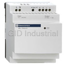
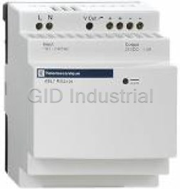
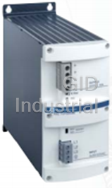


What they say about us
FANTASTIC RESOURCE
One of our top priorities is maintaining our business with precision, and we are constantly looking for affiliates that can help us achieve our goal. With the aid of GID Industrial, our obsolete product management has never been more efficient. They have been a great resource to our company, and have quickly become a go-to supplier on our list!
Bucher Emhart Glass
EXCELLENT SERVICE
With our strict fundamentals and high expectations, we were surprised when we came across GID Industrial and their competitive pricing. When we approached them with our issue, they were incredibly confident in being able to provide us with a seamless solution at the best price for us. GID Industrial quickly understood our needs and provided us with excellent service, as well as fully tested product to ensure what we received would be the right fit for our company.
Fuji
HARD TO FIND A BETTER PROVIDER
Our company provides services to aid in the manufacture of technological products, such as semiconductors and flat panel displays, and often searching for distributors of obsolete product we require can waste time and money. Finding GID Industrial proved to be a great asset to our company, with cost effective solutions and superior knowledge on all of their materials, it’d be hard to find a better provider of obsolete or hard to find products.
Applied Materials
CONSISTENTLY DELIVERS QUALITY SOLUTIONS
Over the years, the equipment used in our company becomes discontinued, but they’re still of great use to us and our customers. Once these products are no longer available through the manufacturer, finding a reliable, quick supplier is a necessity, and luckily for us, GID Industrial has provided the most trustworthy, quality solutions to our obsolete component needs.
Nidec Vamco
TERRIFIC RESOURCE
This company has been a terrific help to us (I work for Trican Well Service) in sourcing the Micron Ram Memory we needed for our Siemens computers. Great service! And great pricing! I know when the product is shipping and when it will arrive, all the way through the ordering process.
Trican Well Service
GO TO SOURCE
When I can't find an obsolete part, I first call GID and they'll come up with my parts every time. Great customer service and follow up as well. Scott emails me from time to time to touch base and see if we're having trouble finding something.....which is often with our 25 yr old equipment.
ConAgra Foods