

 Manufacturers
PANASONIC GP-XC12ML-P
Description
Panasonic GP-XC12ML-P Sensor - M12 Threaded Head, Unshielded 0 - 0.197 in +/- 5V PNP
Part Number
GP-XC12ML-P
Price
Request Quote
Manufacturer
PANASONIC
Lead Time
Request Quote
Category
PRODUCTS - G
Specifications
Accessory
ATA4811 (Controller mounting frame): 1 set
Ambient Humidity
35 to 85 % RH, Storage: 35 to 85 % RH
Ambient Temperature
0 to +50 °C +32 to +122 °F (No dew condensation),
Analog voltage outputs
Output voltage: -5 to +5 V (Note 4), Output impedance: 100 O approx.
Comparative outputs (HI, GO, LO)
PNP open-collector transistor. Maximum source current: 100 mA. Applied voltage: 30 V DC or less (between comparative output and 0 V). Residual voltage: 1.6 V or less (at 100 mA source current) 0.4 V or less (at 16 mA sink current)
Current consumption
150 mA or less
EMC
EN 61000-6-2, EN 61000-6-4
External input
Photo-coupler input. Input current: 9 mA or less. Operating voltage: ON voltage 17 V or more (between +24 V and input). OFF voltage 4 V or less (between +24 V and input) Input impedance: 5 kO approx.
GO
Green LED (lights up when within the upper and lower limit value)
HI
Orange LED (lights up when the upper limit value is exceeded)
Indicators
MODE Orange LED (lights up when in mode status)
Linearity (Note 2)
Within ±0.3 % F.S.
LO
Orange LED (lights up when less than the lower limit value)
Lower level digital display part
5 digit green LED (display of numerical values within the upper and lower limit value)
Material
Enclosure: Polycarbonate
Output Number
HI / GO / LO 3 value output
Output operation
HI : ON when measured value > the upper limit value GO: ON when upper limit value / measured value / lower limit value LO : ON when lower limit value > measured value
Pollution Degree
3 (Industrial environment)
Resolution (Note 2)
GP-XC3SE / GP-XC5SE: 0.04 % F.S. (64 times average processing)
Response Time
75 µs (maximum speed)
Sampling frequency
40 kHz (25 µs)
Serial I/O
RS-232C
Shock Resistance
100 m/s2 acceleration (10 G approx.) in X, Y and Z directions for five times each
Short-Circuit Protection
Incorporated
Supply Voltage
24 V DC ± 10 % Ripple P-P 10 % or less
Temperature characteristics (Note 3)
0.07 % F.S./°C or less
Timing
Green LED (lights up as per the external or internal trigger timing)
Upper level digital display part
5 digit orange LED (display of numerical values out of upper and lower limit value)
Utilization category
DC-12 or DC-13
Vibration Resistance
10 to 55 Hz frequency, 0.75 mm 0.030 in amplitude in X, Y and Z directions for two hours each
Weight
Net weight: 120 g approx.
Zero-set setting method
Push button setting / External input setting
Features
- Height Sensing Mode
- Manual Setting Mode
- Rotation/Eccentricity/Vibration Mode
- Stroke End Sensing Mode
- The 5-digit, dual, 2-color digital display offers great visibility
Datasheet

Extracted Text
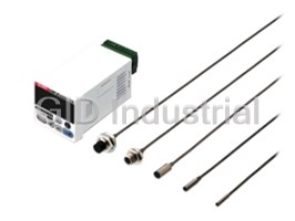
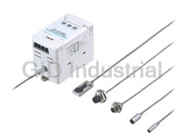
High Speed • High Accuracy Eddy Current Type Digital Displacement Sensor
GP-X SERIES
Conforming to
EMC Directive
25!s & 0.02%F.S.
High-speed sampling and high resolution.
The new choice for even more variegated data collection and processing.
The unique sensing technology developed by our SUNX team has made possible
an ultra-high speed minute displacement measurement function, essential for
high-precision processes, that boasts the highest resolution in the industry.
We’ve realized a 25 ¨s (40,000 They perform with a �0.3 %F.S.
times / sec.) ultra high sampling speed linearity for stainless steel and iron
With a 25 !s ultra high sampling speed, the GP-X series won’t miss Because they perform with a �0.3 % F.S. linearity, they can be used for
even high speed work displacements. sensing stainless steel and iron enabling precise measurements not affected by
the work’s material. Specifications corresponding to each material (stainless
steel, iron, aluminum) has already been inputted in the controller enabling the
These devices boast a 0.07 % F.S. / �C
easy selection of the setting that is most suitable for the particular material used.
temperature characteristics Optimal correction of the output feature
By combining the sensor head with the controller, we’ve realized
Aluminum Stainless steel
0.07 % F.S. / �C. They are highly resistant to ambient temperature
changes enabling stable micro-displacement measurements.
They possess a 0.02 % F.S. resolution
Iron
for highly accurate measurement
With the industry’s highest resolution, 0.02 % F.S. (Note), they can
perform high-accuracy measurements of micro-displacements.
(Average number of samples: 64)
Distance Distance
Note: GP-XC3SE and GP-XC5SE Resolution: 0.04 %F.S.
Before correction After correction
1
Output value
Output value
A total of 6 types of sensor head
6 types of sensor heads from the ultra compact "3.8 mm "0.150 in cylindrical type to the
long range sensing "22 mm "0.866 in / M12 screw type are available.
GP-X22KL
Sensing range : 0 to 10 mm
0 to 0.394 in
Appearance : "22 mm / M12
"0.866 in
Controller
GP-X12ML
Sensing range : 0 to 5 mm
NPN output type , PNP output type
0 to 0.197 in
DIN � 48 mm 1.890 in size
Appearance : M12
GP-X10M GP-X3SE GP-X5SE GP-X8S
Sensing range : 0 to 2 mm Sensing range : 0 to 0.8 mm Sensing range : 0 to 1 mm Sensing range : 0 to 2 mm
0 to 0.079 in 0 to 0.031 in 0 to 0.039 in 0 to 0.079 in
Appearance : M10 Appearance : "3.8 mm Appearance : "5.4 mm Appearance : "8 mm
"0.150 in "0.213 in "0.315 in
Sensor heads with superior workability and maintainability
Replacement of sensor heads possible One-touch connector hook up Sensor head extensions possible
Between the sensor head and the
As a result of damage or other mishap The sensor head and the controller connection
controller, a GP-XCCJ7 extension cable
rendering maintenance necessary, you is a simple one-touch connector type.
(optional) can be used up to a 10 m
can replace only the sensor head leaving
32.808 ft total length.
the controller as it is.
One-touch
connector
Sensor head Extension Cable
GP-XCCJ7 : 7 m 22.966 ft
Total length : 10 m
32.808 ft
Sensor cable : 3 m
9.843 ft
2
The SUNX sensor design policy has realized controllers
that are easy to use on-site.
Panel mounting type
Controller
Compact type DIN � 48 mm 1.890 in size
Out of setting range
(upper threshold)
Sensing values within
setting range
Out of setting range
(lower threshold)
The 5-digit, dual, 2-color
digital display offers great
visibility
If the measurement results fall within the
setting range (GO), they will appear on the
Sensing values
lower digital display in green. If they are out
of range (HI, LO), they will be displayed in
the upper digital in orange. The display Setting value verifiable
Simple setting mode Upper threshold value
position and color change allows for
Manual mode even in sensing mode
accurate visibility even for momentary
changes.
Digital input display
enabling easy setting
Its dual digital display enables numerical
setting while verifying setting items for each
Average number of Lower threshold value
mode. Even when sensing, it enables the
samples setting value
verification of the main settings.
3
Various functions made available through
the use of RS-232C standard interfaces.
Exclusive RS-232C cable
(Accessory for the intelligent monitor GP-XAiM)
Cable length : 3 m 9.843 ft
[PC side connector : D-SUB (9 pins)]
Link cable for controller communication
unit (optional) SL-F�
Cable length : 150 mm 5.906 in,
250 mm 9.843 in,
1,000 mm 39.370 in
Controller
communication unit
GP-XCOM
The RS-232C communication
connector is standard equipment
It is capable of various controls such as saving
measurement data to PC and the controller’s inputted
settings and loading stored memory.
Connector for RS-232C
communication
5
Intelligent monitor (GP-XAiM) optimal for
collecting and analyzing measurement data.
(Exclusive RC-232C cable is attached)
An intelligent monitor capable of the settings for each measurement
conditions and waveform display monitoring. It can perform
waveform monitoring, which could until now only be done by the
oscilloscope, as well as the simple loading and saving onto a PC of
settings for each condition and function.
Enables sensors data comparisons
Sensor A and sensor B
Sensor B Sensor A and calculations
can be linked together
and measurement can 3-value judgment output for calculating measurement data
be calculated (a – b) to conformity and calculation results between 2 interconnected
detect difference in controllers is rendered possible. The calculation function equipment
object. renders digital panel controllers unnecessary.
(a – b)
b
a
Datalink between sensors possible
The controller communication unit GP-XCOM (optional) can be
object
(a – b) : difference in object
linked to up to 8 controllers and load via just one RS-232C cable
each controller settings and measurement data to a PC.
Maximum of eight controllers
Data sent to
Controller communication unit a PC via the
Link cable
RS-232C
6
GP-X
ORDER GUIDE
Appearance (mm in)
Set Model No.
Type Sensing range Comparative output
(Sensor head model No.)
Sensor heads Controller
GP-XC3SE
NPN open-collector
"3.8
"0.150 transistor
(GP-X3SE) (Note)
0 to 0.8 mm
0 to 0.031 in
GP-XC3SE-P PNP open-collector
17
0.669
transistor
(GP-X3SE) (Note)
GP-XC5SE NPN open-collector
"5.4
"0.213 transistor
(GP-X5SE) (Note)
0 to 1 mm
0 to 0.039 in
GP-XC5SE-P
PNP open-collector
17
transistor
0.669 (GP-X5SE) (Note)
GP-XC8S NPN open-collector
83
transistor
(GP-X8S)
0 to 2 mm
3.268
0 to 0.079 in
"8
GP-XC8S-P PNP open-collector
17
"0.315
transistor
(GP-X8S)
0.669
48
1.890
GP-XC10M
NPN open-collector
transistor
(GP-X10M)
0 to 2 mm
0 to 0.079 in
48
M10 GP-XC10M-P PNP open-collector
1.890
17
transistor
(GP-X10M)
0.669
GP-XC12ML NPN open-collector
transistor
(GP-X12ML)
0 to 5 mm
0 to 0.197 in
GP-XC12ML-P
M12 PNP open-collector
21
transistor
0.827 (GP-X12ML)
GP-XC22KL NPN open-collector
transistor
(GP-X22KL)
0 to 10 mm
M12
0 to 0.394 in
GP-XC22KL-P PNP open-collector
"22
35
0.866
transistor
(GP-X22KL)
1.378
Note: High resolution types (GP-XC3S, GP-XC5S: 0.02 % F.S., average number of samples: 64) are available. These products correspond to the Export
Trade Administration Act of Japan. Shipping them outside Japan requires special permission from the Japanese government regarding stipulations in
Foreign Exchange and Foreign Trade Law. Please contact our office for details.
OPTIONS
Designation Model No. Description
This unit outputs measurement values in BCD data format at a high speed.
BCD output unit
GP-XBCD
• Sampling frequency : 20 kHz
Cable with connector
Cable for BCD data output unit.
on one end for GP-XBCC3 Length: 3 m 9.843 ft
• 26-core cable with connector on one end
BCD output unit
Controller
Up to 8 controllers can be linked.
GP-XCOM
communication unit
Length: 150 mm 5.906 in
SL-F150
Link cable for
This cable links the controller communication
controller Length: 250 mm 9.843 in
SL-F250
units. Select as per the cable length.
communication unit
Length: 1,000 mm 39.370 in
SL-F1000
Monitoring settings for each measurement condition and measurement
Intelligent monitor GP-XAiM waveforms is enabled by way of a PC.
• One exclusive RS-232C cable (3 m 9.843 ft length) is attached.
Extension cable for This cable with connector is for extensions
Length: 7 m 22.966 ft
GP-XCCJ7
between the sensor head and controller.
sensor head
Extension cable for
BCD output unit Controller communication unit Intelligent monitor
sensor head
Cable with connector on Link cable for controller • GP-XAiM
• GP-XCCJ7
one end for BCD communication
output unit unit
Controller
BCD output unit
communication unit
GP-XBCD
GP-XCOM
Link cable for controller
Cable with connector on one end communication unit
for BCD output unit GP-XBCC3 SL-F�
7
Threaded type sensor head Non-threaded type sensor head
GP-X
SPECIFICATIONS
Sensor heads
Non-threaded type Threaded type
Type
For 0.8 mm 0.031 in sensing For 1 mm 0.039 in sensing For 2 mm 0.079 in sensing For 2 mm 0.079 in sensing For 5 mm 0.197 in sensing For 10 mm 0.394 in sensing
Item Model No. GP-X3SE GP-X5SE GP-X8S GP-X10M GP-X12ML GP-X22KL
Sensing range (Note 1) 0 to 0.8 mm 0 to 0.031 in 0 to 1 mm 0 to 0.039 in 0 to 2 mm 0 to 0.079 in 0 to 2 mm 0 to 0.079 in 0 to 5 mm 0 to 0.197 in 0 to 10 mm 0 to 0.394 in
Standard sensing object Stainless steel (SUS304) / Iron sheet [Cold rolled carbon steel (SPCC)] 60�60�t 1 mm 2.362�2.362�t 0.039 in
Temperature characteristics (Note 2) 0.07 % F.S./�C or less
Pollution degree 3 (Industrial environment)
Protection IP67 (IEC), IP67g (JEM)
Ambient temperature �10 to�55 �C �14 to�131 �F, Storage: �20 to�70 �C �4 to�158 �F
Ambient humidity 35 to 85 % RH, Storage: 35 to 85 % RH
Voltage withstandability 250 V AC for one min. between all supply terminals connected together and enclosure
Insulation resistance 20 MΩ, or more, with 250 V DC megger between all supply terminals connected together and enclosure
Vibration resistance
10 to 150 Hz frequency, 0.75 mm 0.030 in amplitude in X, Y and Z directions for two hours each
2
Shock resistance 500 m/s acceleration (50 G approx.) in X, Y and Z directions for five times each
Enclosure Stainless steel (SUS303) Brass (Nickel plated)
Cable protector PP
Sensing Part ABS PAR ABS PA
Cable High frequency coaxial cable with connector, 3 m 9.843 ft long (Note 3)
Extension up to total 10 m 32.808 ft is possible with the optional cable
Cable extension
Weight (Note 4) 40 g approx. 40 g approx. 40 g approx. 50 g approx. 45 g approx. 80 g approx.
Accessories Nut: 2 pcs., Toothed lock washer: 1 pc.
Notes: 1) The sensing range is specified for the standard sensing object.
2) This value represents 20 to 60 % of the maximum sensing distance when combining the sensor head and the controller.
3) For the flexible cable type, please contact our office.
4) The given weight of the threaded type sensor head is the value including the weight of the nuts and the toothed lock washer.
8
Material Environmental resistance
GP-X
SPECIFICATIONS
Controllers
Type
NPN output PNP output
Item Set model No.
GP-XC� GP-XC�-P
Supply voltage 24 V DC �10 % Ripple P-P 10 % or less
Current consumption 150 mA or less
GP-XC3SE / GP-XC5SE: 0.04 % F.S. (64 times average processing)
Resolution (Note 1)
GP-XC8S / GP-XC10M / GP-XC12ML / GP-XC22KL: 0.02 % F.S. (64 times average processing)
Sampling frequency 40 kHz (25 !s)
Linearity (Note 1)
Within �0.3 % F.S.
Temperature characteristics (Note 2) 0.07 % F.S./�C or less
Analog voltage output Output voltage: �5 to �5 V (Note 3), Output impedance: 100 Ω approx.
Response time
75 !s (maximum speed)
NPN open-collector transistor PNP open-collector transistor
• Maximum sink current: 100 mA • Maximum source current: 100 mA
Comparative outputs
• Applied voltage: 30 V DC or less (between comparative output and 0 V) • Applied voltage: 30 V DC or less (between comparative output and �V)
(HI, GO, LO)
• Residual voltage: 1.6 V or less (at 100 mA sink current) • Residual voltage: 1.6 V or less (at 100 mA source current)
0.4 V or less (at 16 mA sink current) 0.4 V or less (at 16 mA source current)
Utilization category DC-12 or DC-13
Output number
HI / GO / LO 3 value output
HI : ON when measured value � the upper limit value
Output operation GO: ON when upper limit value j measured value j lower limit value
LO : ON when lower limit value � measured value
Short-circuit protection Incorporated
Photocoupler input Photocoupler input
• Input current: 9 mA or less • Input current: 9 mA or less
External input • Operating voltage: ON voltage 17 V or more (between �24 V and input) • Operating voltage: ON voltage 17 V or more (between 0 V and input)
OFF voltage 4 V or less (between �24 V and input) OFF voltage 4 V or less (between 0 V and input)
• Input impedance: 5 kΩ approx. • Input impedance: 5 kΩ approx.
Serial I/O
RS-232C
Zero-set setting method Push button setting / External input setting
MODE Orange LED (lights up when in mode status)
HI
Orange LED (lights up when the upper limit value is exceeded)
GO Green LED (lights up when within the upper and lower limit values)
LO Orange LED (lights up when less than the lower limit value)
TIMING
Green LED (lights up as per the external or internal trigger timing)
Upper line digital display part 5 digit orange LED (display of numerical values out of upper and lower limit values)
Lower line digital display part
5 digit green LED (display of numerical values within the upper and lower limit values)
Pollution degree
3 (Industrial environment)
Ambient temperature 0 to�50 �C �32 to �122 �F (No dew condensation), Storage: 0 to�50 �C �32 to �122 �F
Ambient humidity
35 to 85 % RH, Storage: 35 to 85 % RH
EMC EN 61000-6-2, EN 61000-6-4
Vibration resistance 10 to 55 Hz frequency, 0.75 mm 0.030 in amplitude in X, Y and Z directions for two hours each
2
Shock resistance
100 m/s acceleration (10 G approx.) in X, Y and Z directions for five times each
Material Enclosure: Polycarbonate
Weight 120 g approx.
Accessory
ATA4811 (controller mounting frame): 1 set
Notes: 1) This value is obtained at a constant �25 �C �77 �F.
2) This value represents 20 to 60 % of the maximum sensing distance when combining the sensor head and the controller.
3) Adjusted to a 0 to �5 V factory setting.
BCD output unit Controller communication unit
Model No. GP-XCOM
Model No. GP-XBCD
Current consumption
20 mA or less Current consumption 5 mA or less
N-channel MOSFET open drain
Output
Material Enclosure: ABS
• Maximum sink current: 50 mA
5 digits BCD,
• Applied voltage: 30 V DC or less (between output and GND) Weight 20 g approx.
Polarity indication,
()
• Residual voltage: 1 V or less (at 50 mA sink current)
VALID
Accessory Mounting bracket [Stainless steel (SUS304)]: 1 pc.
Non-voltage contact or NPN open-collector transistor input
Hold input
• Low: 0 to 1 V • High: Open
Note: Each GP-XCOM is connected using a link cable for controller com-
munication units (SL-F�, optional).
Material Enclosure: ABS
When GP-XCOM is used, controllers cannot communicate if their
Weight software versions are not compatible (Ver. 1.06 or earlier version with
30 g approx.
Ver 2.00 or later version).
Accessory
Mounting bracket [Stainless steel (SUS304)]: 1 pc.
Check the software version and use the correct combination.
Note: Connects to the control device with GP-XBCC3 cable with connector
on one end for BCD output unit (3 m 9.843 ft cable length, optional).
9
Environmental resistance Indicators
GP-X
I/O CIRCUIT AND WIRING DIAGRAMS
NPN output PNP output
type controller type controller
I/O circuit diagram I/O circuit diagram
Terminal No. Terminal No.
D1 D1
�V �V
18 18
Comparative
Load
ZD1 output LO
1 4 Output COM.
Tr1
Load
100mA max.
Comparative 100mA max.
ZD2
Tr1
2 output GO 1
Tr2 Load
ZD1 Comparative output LO
100mA max.
ZD3
Comparative output HI 100mA max.
Load Tr2
3 2
� �
Tr3
24 V DC 24V DC
ZD2 Comparative output GO
100mA max.
Load
ZD4 Alarm output 100mA max.
Load �10 % �10%
Tr3
5 � 3 �
Tr4
ZD3 Comparative output HI
Load
100mA max.
100mA max.
ZD5 Strobe output
Tr4
6 5
Tr5
Load
100 mA max. ZD4 Alarm output
100mA max.
ZD6
Interference Used for interference Tr5
Load
7 6
Tr6
prevention output Strobe output
prevention function. ZD5
Load
4 Interference prevention output
Output COM.
0 V Used for interference
Tr6
17 7
prevention function.
ZD6
47 Ω 47 Ω
�
17
9 Analog voltage output (�5 to �5 V) (Note)
�
0 V
8 For analog output GND 47 Ω 47 Ω
�
9 Analog voltage output (�5 to �5 V) (Note)
�
�24 V
8 For analog output GND
5 kΩ Zero-set input Input COM. (�24 V)
13
10
m1 m1 m1 m2 m1
�24 V
5 kΩ
Memory selection input 1
11
5 kΩ
Zero-set input
10
�24 V
5 kΩ
Memory selection input 2
12
5 kΩ Memory selection input 1
11
�24 V
5 kΩ
Timing input
5 kΩ Memory selection input 2
14
12
�24 V
5 kΩ Timing input
14
5 kΩ
Reset input
15
5 kΩ Reset input
�24 V
Interference prevention input 15
5 kΩ
Used for interference
16
m1 m2 m1 m1 m1
prevention function.
5 kΩ
Interference Used for interference
16
prevention function.
prevention input
Input COM.
13
(0 V)
Internal circuit Users’ circuit Internal circuit Users’ circuit
Note: Devices connected to the analog voltage output must have an input Note: Devices connected to the analog voltage output must have an input
impedance set at 1 MΩ or more. impedance set at 1 MΩ or more.
Symbols D1: Reverse supply polarity protection diode Symbols D1: Reverse supply polarity protection diode
��� ���
ZD1 to ZD6: Surge absorption zener diode ZD1 to ZD6: Surge absorption zener diode
Tr1 to Tr6: NPN output transistor Tr1 to Tr6: PNP output transistor
m1 m1
Non-voltage contact or NPN open-collector transistor Non-voltage contact or PNP open-collector transistor
or or
• Zero-set input, reset input, memory selection input • Zero-set input, reset input, memory selection input
Low (0 to 4 V) : Effective Low (0 V or open) : Ineffective
High (�V or open) : Ineffective High (�17 V to�24 V) : Effective
m2 m2
NPN open-collector transistor PNP open-collector transistor
• Timing input • Timing input
Low (0 to 4 V): Effective Low (0 V or open): Ineffective
High (�V or open): Ineffective High (�17 to �24 V): Effective
Memory selection input Memory selection input
Memory No. Memory selection 1 Memory selection 2 Memory No. Memory selection 1 Memory selection 2
0 High High 0 Low Low
1 Low High
1 High Low
2 High Low 2 Low High
3 Low Low 3 High High
10
Main circuit
Main circuit
25 24 23 22 21 20 19 18 17 16 15 14 13 12 11 10 9 8 7 6 5 4 3 2 1
GP-X
I/O CIRCUIT AND WIRING DIAGRAMS
Controller
Terminal arrangement
123456789
0ABCDEFGH
Connector for RS-232C
communication
Connector for
sensor head connection
Terminal No. Description Terminal No. Description
1 Comparative output LO 0 Zero-set input
2 A
Comparative output GO Memory selection input 1
3 Comparative output HI B Memory selection input 2
4 C
Output COM. Input COM.
5D Alarm output Timing input
6 E
Strobe output Reset input
7 Interference prevention output F Interference prevention input
8 G
For analog output GND 0 V
9 Analog output H
�V
BCD output unit
Connector pin position and cable color
Connector Cable
Signal Description
pin No.
Sheath color ID mark
1
Orange Red: 1 A0 1�
2
Orange Black: 1 B0 2� Measurement value
0
3 C0 to the 10 digit
Gray Red: 1 4�
4
Gray Black: 1 D0 8�
5 White A1
Red: 1 1�
6
White Black: 1 B1 2� Measurement value
1
7 Yellow Red: 1 C1 4� to the 10 digit
8
Yellow Black: 1 D1 8�
Connector for controller connection
9
Pink Red: 1 A2 1�
0
Pink Black: 1 B2 2� Measurement value Measurement value
2
A
Orange Red: 2 C2 4� to the 10 digit BCD output
B D2
Orange Black: 2 8�
C
Gray Red: 2 A3 1�
D Gray B3
Black: 2 2� Measurement value
3
E
White Red: 2 C3 4� to the 10 digit
Connector for BCD output
F
White D3 8�
Black: 2
G A4
Yellow Red: 2 1�
H
Yellow Black: 2 B4 2� Measurement value
4
I C4 to the 10 digit
Pink Red: 2 4�
J
Pink Black: 2 D4 8�
K Polarity signal output High (OFF): �, Low (ON): �
Orange Red: 3 POLE
Low (ON) when the
L
Orange Black: 3 VALID output
VALID
data output is enabled
This input is to maintain the external
M
Gray Red: 3 HOLD Hold input data output. The data output is
maintained during low (ON).
N Gray Ground
Black: 3 GND
O
White Red: 3 GND Ground
White Black: 3 Not connected Not used
Note: The shield wire is connected externally at 0 V.
11
GP-X
PRECAUTIONS FOR PROPER USE
Mounting with nut
This product is not a safety sensor. Its use is not
intended or designed to protect life and prevent body
Frequently asked questions
What makes Elite.Parts unique?

What kind of warranty will the GP-XC12ML-P have?
Which carriers does Elite.Parts work with?
Will Elite.Parts sell to me even though I live outside the USA?
I have a preferred payment method. Will Elite.Parts accept it?
Why buy from GID?

Quality
We are industry veterans who take pride in our work

Protection
Avoid the dangers of risky trading in the gray market

Access
Our network of suppliers is ready and at your disposal

Savings
Maintain legacy systems to prevent costly downtime

Speed
Time is of the essence, and we are respectful of yours
Related Products
Request a Quote

The quote request has been received
Close

Facing challenges or have inquiries? Feel free to contact us!
Call Us +1-469-283-2440
What they say about us
FANTASTIC RESOURCE
One of our top priorities is maintaining our business with precision, and we are constantly looking for affiliates that can help us achieve our goal. With the aid of GID Industrial, our obsolete product management has never been more efficient. They have been a great resource to our company, and have quickly become a go-to supplier on our list!
Bucher Emhart Glass
EXCELLENT SERVICE
With our strict fundamentals and high expectations, we were surprised when we came across GID Industrial and their competitive pricing. When we approached them with our issue, they were incredibly confident in being able to provide us with a seamless solution at the best price for us. GID Industrial quickly understood our needs and provided us with excellent service, as well as fully tested product to ensure what we received would be the right fit for our company.
Fuji
HARD TO FIND A BETTER PROVIDER
Our company provides services to aid in the manufacture of technological products, such as semiconductors and flat panel displays, and often searching for distributors of obsolete product we require can waste time and money. Finding GID Industrial proved to be a great asset to our company, with cost effective solutions and superior knowledge on all of their materials, it’d be hard to find a better provider of obsolete or hard to find products.
Applied Materials
CONSISTENTLY DELIVERS QUALITY SOLUTIONS
Over the years, the equipment used in our company becomes discontinued, but they’re still of great use to us and our customers. Once these products are no longer available through the manufacturer, finding a reliable, quick supplier is a necessity, and luckily for us, GID Industrial has provided the most trustworthy, quality solutions to our obsolete component needs.
Nidec Vamco
TERRIFIC RESOURCE
This company has been a terrific help to us (I work for Trican Well Service) in sourcing the Micron Ram Memory we needed for our Siemens computers. Great service! And great pricing! I know when the product is shipping and when it will arrive, all the way through the ordering process.
Trican Well Service
GO TO SOURCE
When I can't find an obsolete part, I first call GID and they'll come up with my parts every time. Great customer service and follow up as well. Scott emails me from time to time to touch base and see if we're having trouble finding something.....which is often with our 25 yr old equipment.
ConAgra Foods