

 Manufacturers
PANASONIC GP-A14FI
Description
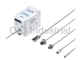
Panasonic GP-A14FI Sensor - Rectangular high accuracy inductive head, 0-3mm, different-frq, qd
Part Number
GP-A14FI
Price
Request Quote
Manufacturer
PANASONIC
Lead Time
Request Quote
Category
PRODUCTS - G
Specifications
Adjustments
(1) Shift adjustment (by push-buttons), (2) Span adjustment (by 14-turn adjuster)
Alarm indicator
Yellow LED (lights up when the alarm output is ON)
Alarm output
NPN open-collector transistor Maximum sink current: 100 mA Applied voltage: 30 V DC or less (between alarm output and 0 V) Residual voltage: 1.6 V or less (at 100 mA sink current) 0.4 V or less (at 16 mA sink current)
Analog output (Analog voltage output Analog current output)
Analog voltage Output voltage: 0 to 5 V Output impedance: 100 O approx. Analog current Output current: 4 to 20 mA Load resistance: 0 to 350 O
Current consumption
150 mA or less
External zero-adjustment input
Input condition: Non-voltage contact or NPN open-collector transistor input Signal condition: Low ... 0 to 1 V (duration 30 ms or more) High ... 5 to 30 V, or open Operation: Low ... External zero-adjustment setting High ... External zero-adjustment ineffective
Linearity
Within ±0.5 % F.S.
Output operation
Turns ON when the sensor head connection is improper or the sensor head cable is disconnected
Over indicator
Orange LED (lights up when sensing range is exceeded)
Power Indicator
Green LED (lights up when the power is ON)
Resolution
0.04 % F.S.
Response Frequency
1.6 kHz (-3 dB)
Sensing range
0 to 3 mm 0 to 0.118 in
Standard sensing object
Iron sheet 15 x 15 x t 1 mm 0.591 x 0.591 x t 0.039 in
Zero-adjustment setting method
Push button setting / External input setting
Features
- Accurate measurement of minute displacements
- Compact amplifier
- Equipped with a zero-adjustment function
- Equipped with useful indicators
- Fine adjustment of output
- High Accuracy Eddy Current Type Displacement Sensor
Datasheet

Extracted Text
GP-A SERIES
High Accuracy Eddy Current Type Displacement Sensor
High accuracy analog
sensing of minute
displacement
Accurate measurement of minute displacements Linearity �0.5 % F.S. Stable temperature characteristics
Minute displacement of metallic Displacement is accurately output These sensor heads boast a 2 mm
objects can be accurately measured since it incorporates a high accuracy 0.079 in or more sensing range
with a resolution of 0.04 % F.S. linearity correction circuit. enabling 0.03 % F.S./°C. (Excluding
GP-A5S (For 1 mm 0.039 in sensing type) the different frequency type)
[ ]
Resolution: 0.4 !m 0.016 mil GP-A8S (For 2 mm 0.079 in sensing type)
Temperature characteristics: 0.6 !m /°C
[ ]
0.024 mil /°C
The sensor head protected as per IP67g (JEM) Sensor heads can be mounted in narrow spaces Choice of sensor heads
You can choose from among 5 types of
With IP67g environment resistance, If mounting standard types and
sensor heads depending on the
variegated measurements are ren- different frequency types parallel to
mounting space available and the
dered possible under many different each other, they use up one-third the
application. Also, their cable joints are
conditions. space needed for mounting compared
equipped with a special protector that
to the same models. In addition, the
helps prevent the cable from severing
GP-A14F type can be mounted close
as a result of bending or other mishap.
together and the sensor heads can be
set in a narrow range for distortion and
GP-A5S(I) GP-A8S(I) GP-A10M(I)
other difficult measurements.
Sensors can be customized for metals other than steel Easy hookup connector type
"5.4 mm
"8 mm
M10
It is now possible to customize sensors Because the sensor heads and the "0.213 in
"0.315 in
to meet your metal measurement amplifier are connected with a
requirements. connector, they can be set up with
GP-A14F(I) GP-A12ML(I)
Performance may vary depending one touch. This resolves the problem
5.4 mm
0.213 in
on conditions. Please contact our of measurements impaired by
()
office. connection resistance fluctuations
34 mm
occurring with terminal types. 1.339 in
15 mm M12
0.591 in
986
GP-A GP-X LD LA LA-300 HL-T1 LM10 LH-50 HL-C1
MEASUREMENT SENSORS
Magnetic Displacement Light / Thru-beam Type Light / Reflective Type
GP-A
APPLICATIONS
Measuring iron sheet thickness Measuring gap between rollers Measuring parallelism of chassis
In combination with the digital panel Fine gap measurement is possible to Even a slight tilt can be reliably
controller CA series, it is optimally control the gap between rollers. detected.
suited for measuring thickness of
continuous iron sheets.
Equipped with a zero-adjustment function Fine adjustment of output
By pressing the zero-adjustment button, Fine adjustment according to the sensing conditions is possible with shift and span
you can reset the output voltage to 0 V functions.
with one touch. (Resets the current
Shift adjustment Span adjustment
output to 4 mA)
This function comes in handy when
�5 V
performing tolerance diagnosis of a
Shift adjustment
masterwork to be used as the standard.
range: �0.5 V
6.5 V
Zero-adjustment
Easy adjustment for product changes.
settable range
Remote operation is also possible by
5 V
()
0 V
way of an external input.
3.5 V
Maximum
distance
Shift adjustment
�5 V range: �0.5 V
0 V
Maximum distance
Equipped with useful indicators Compact amplifier
The amplifier is equipped with an
The amplifier has a W53�H90�D67 mm
ALARM indicator (yellow), which lights
W2.087�H3.543�D2.638 in compact
up in case of sensor head cable
size. Of course, it is mountable on a
disconnection or sensor head damage,
35 mm 1.378 in width DIN rail.
and an OVER indicator (orange),
53 mm
which lights up in case the sensing
2.087 in
90 mm
range is exceeded.
Suitable for various analog control devices
3.543 in
It is suitable for various analog control
devices since it is equipped with two
67 mm
outputs, analog voltage (0 to 5 V) and
2.638 in
analog current (4 to 20 mA).
987
Magnetic Displacement Light / Thru-beam Type Light / Reflective Type
MEASUREMENT SENSORS
GP-A GP-X LD LA LA-300 HL-T1 LM10 LH-50 HL-C1
GP-A
ORDER GUIDE
Please ensure to order the sensor head and the amplifier as a set. The set is calibrated and delivered.
Appearance (mm in)
Type Sensing range Set model No. Output
Sensor heads Amplifier
"5.4 GP-A5S
"0.213
0 to 1 mm
0 to 0.039 in
17
0.669
GP-A5SI
GP-A8S
0 to 2 mm
"8
0 to 0.079 in
17
"0.315
0.669
GP-A8SI
90
3.543
Analog voltage
• Output voltage:
GP-A10M
1 to 5 V
67 0 to 2 mm
M10 2.638
0 to 0.079 in
17
M0.394 Analog current
0.669
GP-A10MI
• Output current:
4 to 20 mA
53
2.087
GP-A12ML
0 to 5 mm
M12
0 to 0.197 in
21
M0.472
0.827
GP-A12MLI
5.4
GP-A14F
0.213
0 to 3 mm
0 to 0.118 in
34
15
1.339 GP-A14FI
0.591
OPTIONS
Sensor head mounting bracket
• MS-SS5
Type Model No. Description
• MS-SS8
• It enables easy fixing of the sensor head.
MS-SS5 Mounting bracket for GP-A5S(I)
Sensor head
mounting bracket
MS-SS8 Mounting bracket for GP-A8S(I)
This is a very small controller which allows
two independent threshold level settings.
• Supply voltage: 24 V DC�10 %
CA2-T1
• No. of inputs: 1 No. (sensor input)
• Input range: 4 to 20 mA (CA2-T1)
�5 V (CA2-T4)
NPN open-collector
• Main functions:
transistor
Digital panel controller
Threshold level setting function, zero-
• CA2 series
adjust function, scale setting function,
CA2-T4 hysteresis setting function, start / hold
function, auto-reference function, power
supply ON-delay function, etc.
Digital panel
controller This is a multi-functional controller having
CA-R1
(Note) Relay-contact mathematical functions, hold function, etc.
CA-R4 • Supply voltage: 100 to 240 V AC�10 %
• CA series
• No. of inputs: 2 Nos. (sensor inputs)
CA-T1
NPN open-collector • Input range: 4 to 20 mA (CA-�1)
transistor �5 V (CA-�4)
CA-T4
• Power supply for sensor: 12 V DC, 150 mA
• Main functions:
CA-B1
Mathematical functions, process number
selection function, hold function, scaling
NPN open-collector
function, auto-reference function, power
transistor
supply ON-delay function, measurement
CA-B4
With BCD output
start delay function, hysteresis setting
function, etc.
Note: For further details, refer to p.864 l for the ultra-compact digital panel controller CA2 series,
and to p.854l for the digital panel controller CA series.
988
GP-A GP-X LD LA LA-300 HL-T1 LM10 LH-50 HL-C1
MEASUREMENT SENSORS
Magnetic Displacement Light / Thru-beam Type Light / Reflective Type
For 3 mm 0.118 in sensing For 5 mm 0.197 in sensing For 2 mm 0.079 in sensing For 1 mm 0.039 in sensing
Front sensing Threaded type Threaded type Non-threaded type Non-threaded type
type sensor head sensor head sensor head sensor head sensor head
Different Different Different Different Different
frequency frequency frequency frequency frequency
GP-A
SPECIFICATIONS
For 1 mm 0.039 in sensing For 2 mm 0.079 in sensing For 5 mm 0.197 in sensing For 3 mm 0.118 in sensing
Non-threaded type sensor head Non-threaded type sensor head Threaded type sensor head Threaded type sensor head Front sensing type sensor head
Type
Different Different Different Different Different
frequency frequency frequency frequency frequency
GP-A5S GP-A5SI GP-A8S GP-A8SI GP-A10M GP-A10MI GP-A12ML GP-A12MLI GP-A14F GP-A14FI
Item Set model No.
Sensing range 0 to 1 mm 0.039 in 0 to 2 mm 0.079 in 0 to 5 mm 0.197 in 0 to 3 mm 0.118 in
Iron sheet 8�8�t 1 mm Iron sheet 12�12�t 1 mm Iron sheet 30�30�t 1 mm Iron sheet 15�15�t 1 mm
Standard sensing object
0.315�0.315�t 0.039 in 0.472�0.472�t 0.039 in00 1.181�1.181�t 0.039 in 0.591�0.591�t 0.039 in
Supply voltage 24 V DC�10 % Ripple P-P 10 % or less
Current consumption 150 mA or less
Analog current
Analog output Analog voltage
• Output current: 4 to 20 mA
Analog voltage output • Output voltage: 0 to 5 V
()
• Load resistance: 0 to 350 Ω
Analog current output • Output impedance: 100 Ω approx.
Response frequency 1.6 kHz (�3 dB)
Resolution 0.04 % F.S.
Linearity Within�0.5 % F.S.
NPN open-collector transistor
• Maximum sink current: 100 mA
Alarm output • Applied voltage: 30 V DC or less (between alarm output and 0 V)
• Residual voltage: 1.6 V or less (at 100 mA sink current)
0.4 V or less (at 16 mA sink current)
Output operation Turns ON when the sensor head connection is improper or the sensor head cable is disconnected.
Short-circuit protection
Input condition: Non-voltage contact or NPN open-collector transistor input
Signal condition: Low ... 0 to 1 V (duration 30 ms or more)
External zero-adjustment input High ... 5 to 30 V, or open
Operation: Low ... External zero-adjustment setting
High ... External zero-adjustment ineffective
Zero-adjustment setting method Push button setting / External input setting
Power indicator Green LED (lights up when the power is ON)
Over indicator Orange LED (lights up when sensing range is exceeded)
Alarm indicator Yellow LED (lights up when the alarm output is ON)
1 2
Adjustments Shift adjustment (by push-buttons), Span adjustment (by 14-turn adjuster)
0.5 !m /°C 0.6 !m /°C 1 !m /°C 0.6 !m /°C 1 !m /°C 1.5 !m /°C 2.5 !m /°C 0.9 !m /°C 1.5 !m /°C
Temperature
Sensor head
0.020 mil /°C 0.024 mil /°C 0.039 mil /°C 0.024 mil /°C 0.039 mil /°C 0.059 mil /°C 0.098 mil /°C 0.035 mil /°C 0.059 mil /°C
characteristics
(Note 1)
Amplifier 0.4 !m /°C 0.016 mil /°C 0.8 !m /°C 0.031 mil /°C 2.0 !m /°C 0.079mil /°C 1.2 !m /°C 0.047 mil /°C
Sensor head IP67 (IEC), IP67 g (JEM)
Protection
Amplifier
�10 to�55 °C �14 to�131 °F , Storage: �20 to�70 °C �4 to�158 °F
Sensor head
Ambient
temperature
Amplifier 0 to�50 °C �32 to�122 °F (No dew condensation), Storage: 0 to�50 °C �32 to�122 °F
Ambient humidity 35 to 85 % RH, Storage: 35 to 85 % RH
Voltage withstandability Sensor head 250 V AC for one min. between all supply terminals connected together and enclosure
Insulation resistance 20 MΩ, or more, with 250 V DC megger between all supply terminals connected together and enclosure
Sensor head
Sensor head 10 to 55 Hz frequency, 1.5 mm 0.059 in amplitude in X, Y and Z directions for two hours each
Vibration resistance
Amplifier 10 to 150 Hz frequency, 0.75 mm 0.030 in amplitude in X, Y and Z directions for two hours each
2
Sensor head 500 m/s acceleration (50 G approx.) in X, Y and Z directions for five times each
Shock resistance
2
Amplifier 100 m/s acceleration (10 G approx.) in X, Y and Z directions for five times each
Enclosure: Stainless steel (SUS303) Enclosure: Stainless steel (SUS303) Enclosure: Brass (Nickel plated) Enclosure: Stainless steel (SUS303)
Sensor head
Sensing part: Polyalylate Sensing part: ABS Sensing part: Nylon Sensing part: ABS
Material
Amplifier Enclosure: ABS
Cable Sensor head Connector attached high frequency coaxial cable, 3 m 9.843 ft long
2
Cable length (Note 2) Amplifier Up to total 100 m 328.084 ft with 0.3 mm , or more, cable
40 g approx. 50 g approx. (Note 3) 45 g approx. (Note 3) 50 g approx.
Sensor head
Weight
Amplifier 170 g approx.
2 pcs. each of M3 countersunk
head screws, spring washers,
Nut: 2 pcs., Toothed lock washer: 1 pc.
Accessories Adjusting screwdriver: 1 pc.
plain washers and M3 nuts
Adjusting screwdriver: 1 pc.
Adjusting screwdriver: 1 pc.
Notes: 1) These values are for a range which is 20 to 60 % of the maximum sensing distance.
2) Take care that the output voltage is reduced due to the resistance of the wiring cable.
3) The given weight of the threaded type sensor head is the value including the weight of the nuts and the toothed lock washer.
989
Magnetic Displacement Light / Thru-beam Type Light / Reflective Type
MEASUREMENT SENSORS
GP-A GP-X LD LA LA-300 HL-T1 LM10 LH-50 HL-C1
GP-A
I/O CIRCUIT AND WIRING DIAGRAMS
I/O circuit diagram Wiring diagram
Terminal No.
Amplifier
m1
Supply voltage
47 Ω 47 Ω �
Analog voltage output External zero-adjustment input
24 V DC�10 %
1
(0 to 5 V) (Note 1)
�
57 6 8
Analog output
20 V (Analog output)
5678
100 Ω
Analog current output
3
(4 to 20 mA) (Note 2)
Alarm output
4
Tr
100 mA max.
POWER OVER ALARM
ZD
5
External
m1
zero-adjustment
D1
6 input
GP-A8S
D2
�V
ANALOG PROXIMITY SENSOR
7
�
24 V DC
MADE IN JAPAN
�10 %
0 V
�
8
1234
Sensor head Internal circuit Users’ circuit
13 2 4
Load
Notes: 1) In case of using the analog voltage output, connect
Analog voltage output (0 to 5 V)
Alarm output
a device having a high input impedance. Also, take
care that the output voltage is reduced due to the
Analog current output (4 to 20 mA)
resistance of the wiring cable.
Notes: 2) The alarm output is not incorporated with a short-
circuit protection circuit. Do not connect it directly Note: After the wiring, make sure to fit the terminal covers. The terminal
to a power supply or a capacitive load. cover having a concave depression at the top should be fitted on the
side having terminal Nos. 1 to 4.
Symbols ... D1: Input protection diode
D2: Reverse supply polarity protection diode
ZD: Surge absorption zener diode
Tr : NPN output transistor
m1
Non-voltage contact or NPN open-collector transistor
Terminal No.
5
or
6
Low (0 to 1 V) (duration 30 ms or more): External zero-adjustment setting
High (5 to 30 V, or open): External zero-adjustment ineffective
SENSING CHARACTERISTICS (TYPICAL)
Correlation between material and output voltage / current
The GP-A series is made for all types of standard iron sensing objects. The graph below describes the output discrepancies
that occur when detecting different types of metals. It is now possible to customize sensors to meet your metal measurement
requirements. For more details, please contact our office.
( )
GP-A8S I
GP-A5S(I)
( )
GP-A10M I
8 8
Stainless
Stainless Stainless
steel
steel steel
Stainless
(SUS304)
(SUS304) (SUS410)
steel
6 6
(SUS410)
520 520
Brass
Aluminum Aluminum
Brass
4 4
Iron Iron
2 2
Sensing object
Sensing object
L
L
12�12�t 1 mm
8�8�t 1 mm
0.472�0.472�t 0.039 in
0.315�0.315�t 0.039 in
4 4
0 0.2 0.4 0.6 0.8 1 0 0.5 1 1.5 2
0.008 0.016 0.024 0.031 0.039 0.020 0.039 0.059 0.079
Setting distance L (mm in) Setting distance L (mm in)
990
GP-A GP-X LD LA LA-300 HL-T1 LM10 LH-50 HL-C1
MEASUREMENT SENSORS
Magnetic Displacement Light / Thru-beam Type Light / Reflective Type
Output voltage (V)
Connector for sensor head connection
Main circuit
Output current (mA)
Load
Output voltage (V)
Output current (mA)
GP-A
SENSING CHARACTERISTICS (TYPICAL)
Correlation between material and output voltage / current
GP-A12ML(I) GP-A14F(I)
8 8
Stainless
Stainless
Stainless
steel
steel
steel
(SUS410)
(SUS304)
(SUS304)
6 Brass 6
Brass
Aluminum Aluminum
5 20 5 20
Iron Iron
4 4
Stainless
steel
(SUS410)
2 2
Sensing object
Sensing object
L
L
15�15�t 1 mm
30�30�t 1 mm
0.591�0.591�t 0.039 in
1.181�1.181�t 0.039 in
4 4
0 1 2 3 4 5 0 1 2 3 4
0.039 0.079 0.118 0.157 0.197 0.039 0.079 0.118 0.157
Setting distance L (mm in) Setting distance L (mm in)
PRECAUTIONS FOR PROPER USE
Mounting sensor head
This product is not a safety sensor. Its use is not
• The tightening torque should be under the value given
intended or designed to protect life and prevent body
below.
injury or property damage from dangerous parts of
machinery. It is a normal object detection sensor.
Mounting with set screw
• Make sure to use an M3 or smaller set screw having a cup-point.
• Make sure to use in combination the sensor head and
amplifier which have the same production serial number
Frequently asked questions
What makes Elite.Parts unique?

What kind of warranty will the GP-A14FI have?
Which carriers does Elite.Parts work with?
Will Elite.Parts sell to me even though I live outside the USA?
I have a preferred payment method. Will Elite.Parts accept it?
Why buy from GID?

Quality
We are industry veterans who take pride in our work

Protection
Avoid the dangers of risky trading in the gray market

Access
Our network of suppliers is ready and at your disposal

Savings
Maintain legacy systems to prevent costly downtime

Speed
Time is of the essence, and we are respectful of yours
Related Products
Request a Quote

The quote request has been received
Close

Facing challenges or have inquiries? Feel free to contact us!
Call Us +1-469-283-2440
What they say about us
FANTASTIC RESOURCE
One of our top priorities is maintaining our business with precision, and we are constantly looking for affiliates that can help us achieve our goal. With the aid of GID Industrial, our obsolete product management has never been more efficient. They have been a great resource to our company, and have quickly become a go-to supplier on our list!
Bucher Emhart Glass
EXCELLENT SERVICE
With our strict fundamentals and high expectations, we were surprised when we came across GID Industrial and their competitive pricing. When we approached them with our issue, they were incredibly confident in being able to provide us with a seamless solution at the best price for us. GID Industrial quickly understood our needs and provided us with excellent service, as well as fully tested product to ensure what we received would be the right fit for our company.
Fuji
HARD TO FIND A BETTER PROVIDER
Our company provides services to aid in the manufacture of technological products, such as semiconductors and flat panel displays, and often searching for distributors of obsolete product we require can waste time and money. Finding GID Industrial proved to be a great asset to our company, with cost effective solutions and superior knowledge on all of their materials, it’d be hard to find a better provider of obsolete or hard to find products.
Applied Materials
CONSISTENTLY DELIVERS QUALITY SOLUTIONS
Over the years, the equipment used in our company becomes discontinued, but they’re still of great use to us and our customers. Once these products are no longer available through the manufacturer, finding a reliable, quick supplier is a necessity, and luckily for us, GID Industrial has provided the most trustworthy, quality solutions to our obsolete component needs.
Nidec Vamco
TERRIFIC RESOURCE
This company has been a terrific help to us (I work for Trican Well Service) in sourcing the Micron Ram Memory we needed for our Siemens computers. Great service! And great pricing! I know when the product is shipping and when it will arrive, all the way through the ordering process.
Trican Well Service
GO TO SOURCE
When I can't find an obsolete part, I first call GID and they'll come up with my parts every time. Great customer service and follow up as well. Scott emails me from time to time to touch base and see if we're having trouble finding something.....which is often with our 25 yr old equipment.
ConAgra Foods