

 Manufacturers
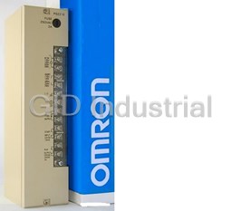
OMRON CQM1-PA203

Description
OMRON CQM1-PA203 Power Supply Module. 18W
Part Number
CQM1-PA203
Price
Request Quote
Manufacturer
OMRON
Lead Time
Request Quote
Category
COMPONENTS
Specifications
Power
18 Watts
Datasheet

Extracted Text
CQM1-PR | CQM1-TER | CQM1-DEM | CQM1-TU | CQM1-ME | CQM1-MP | CQM1-IP | CQM1-PA | CQM1-PD | CQM1-IP Call Today | There Tomorrow OMRON PLCs SYSMAC - CQM1 Memory, Power Supplies & Accessories Presented by - MRO Electric and Supply Company, Inc. For Product Needs: Email: sales@MROELECTRIC.COM Call: 1-800-691-8511 Fax: 919-415-1614 http://www.MROELECTRIC.com/ OMRON System CQM1 MRO ELECTRIC & SUPPLY Company www.mroelectric.com PC Assembly and Installation Section 2-4 2-4 PC Assembly and Installation This section describes how to assemble the Units that make up the CQM1 PC and install the PC on a DIN Track. PC Orientation When installing the CQM1 in the control panel, always mount the Units so that the ventilation openings are facing up. Also, there must be at least a 20-mm space both above and below the PC. Correct Wrong Wrong 2-4-1 Connecting PC Components The Units that make up a CQM1 PC can be connected simply by pressing the Units together and sliding the locking tabs towards the back of the Units. The End Cover is connected in the same way to the Unit on the far right side of the PC. Follow the procedure listed below to connect PC components. Always turn off the CQM1 when connecting or disconnecting Units. Replace Units only after shutting down the CQM1 system. 1, 2, 3... 1. The following diagram shows the connection of two Units that make up a CQM1 PC. Join the Units so that the connectors fit exactly. Connector 2. The yellow locking tabs at the top and bottom of each Unit lock the Units together. Slide these locking tabs towards the back of the Units as shown below. Slider Lock Release 24 PC Assembly and Installation Section 2-4 3. Attach the End Cover to the Unit on the far right side of the PC. End Cover ! Caution Be sure to attach the End Cover to the Unit on the far right side of the PC. The PC will not operate properly if the End Cover is not connected. 2-4-2 DIN Track Installation A CQM1 PC must be installed on DIN Track and secured with the DIN Track Brackets shown below. DIN Track DIN Track Brackets (PFP-M) (PFP-50N or PFP-100N) Use the following procedure to install a CQM1 PC on DIN Track. 1, 2, 3... 1. Mount the DIN Track securely to the control board or inside the control panel using screws in at least 3 separate locations. 2. Release the pins on the backs of the CQM1 Units. These pins lock the PC to the DIN Track. Unlock DIN track mounting pin 3. Fit the back of the PC onto the DIN Track by inserting the top of the track and then pressing in at the bottom of the PC, as shown below. Din track 25 MROELECTRIC.COM Wiring and Connections Section 2-5 4. Lock the pins on the backs of the CQM1 Units. DIN track mounting pin 5. Install a DIN Track Bracket on each side of the PC. To install a bracket, hook the bottom of the Bracket on the bottom of the track, rotate the Bracket to hook the top of the Bracket on the top of the track, and then tighten the screw to lock the Bracket in place. DIN Track Brackets 2-5 Wiring and Connections This section provides basic information on wiring the Power Supply Unit and I/O Units, and on connecting Peripheral Devices. 2-5-1 AC Power Supply Unit Wiring The following diagram shows the proper connection to an AC power supply. The AC voltage should be between 100 and 240 VAC. Refer to 2-2-3 Selecting a Power Supply Unit for details on Power Supply Unit capacity. Remove the seal from the top of the Power Supply Unit only after wiring is com- pleted. This seal must be removed before operating the Unit to prevent over- heating. 2 The cross-sectional area of each wire must be 2 mm min. Insulating transformer Breaker AC power supply An insulating transformer greatly Twist the wires. reduces the noise that may be induced between the power line and ground. Do not ground the secondary side of the insulating transformer. ! Caution Be sure that the AC power supply voltage remains within the allowed fluctuation range of 85 to 264 VAC. CQM1-PA216 is switchable with an input voltage range of 80 to 138 VAC or 160 to 264 VAC. 26 MROELECTRIC.COM Wiring and Connections Section 2-5 Terminal Block The following diagram shows the terminal blocks for the two AC Power Supply Units. CQM1-PA203 CQM1-PA206 CQM1-PA216 Use an AC Use an AC AC Use an AC AC AC power supply power supply of input power supply input input between 100 100 or between 100 and 240 VAC. 230 VAC. and 240 VAC. Noise filter Voltage selector Noise filter neutral Short: 100 VAC LG neutral terminal Open: 230 VAC terminal Protective Protective GR Protective earth terminal earth terminal earth ter- Use the 24 VDC, Use the 24 VDC, minal 0.5 A terminals 0.5 A terminals to supply power to supply power to DC Input to DC Input Units. Units. 2 The wire used should be at least 2 mm . Provide the grounding point as close to the CQM1 PC as possible. ! WARNING LG ( or ): Noise filter neutral terminal. Short-circuit the LG ( or ) terminal and GR ( ) terminals using the attached short-circuit bar and ground them at a resistance of less than 100 Ω to reduce noise and prevent electric shock. ! WARNING GR ( ): 2 Protective earth terminal. Connect to a separate ground wire of at least 2 mm to ground the terminal at a resistance of less than 100 Ω to prevent electric shock. ! Caution Avoid sharing the grounding wire with other equipment or attaching to the beam of a building, otherwise it may cause an adverse effect. Correct Incorrect Other Other CQM1 CQM1 equipment equipment 2-5-2 DC Power Supply Unit Wiring The following diagram shows the proper connection to a DC power supply. Refer to 2-2-3 Selecting a Power Supply Unit for details on Power Supply Unit capacity. Remove the seal from the top of the Power Supply Unit only after wiring is com- pleted. This seal must be removed before operating the Unit to prevent over- heating. Use power lines of 2 mm min. Breaker DC power supply Twist 27 MROELECTRIC.COM Wiring and Connections Section 2-5 ! Caution Be sure that the DC power supply voltage remains within the allowed fluctuation range of 20 to 28 VDC. Terminal Block The following diagram shows the terminal blocks for the DC Power Supply Unit. CQM1-PD026 Provide a 24-VDC DC power supply. input Noise filter neutral terminal Protective earth terminal NC NC 2 The wire used should be at least 2 mm . Provide the grounding point as close to the CQM1 PC as possible. Note To satisfy the EC directives (low-voltage directive), provide reinforced insulation or double insulation for the power supply. ! WARNING LG ( or ): Noise filter neutral terminal. Short-circuit the LG ( ) terminal and GR ( ) terminals using the attached short-circuit bar and ground them at a resistance of less than 100 Ω to reduce noise and prevent electric shock. ! WARNING GR ( ): 2 Protective earth terminal. Connect to a separate ground wire of at least 2 mm to ground the terminal at a resistance of less than 100 Ω to prevent electric shock. Caution Avoid sharing the grounding wire with other equipment or attaching to the beam ! of a building, otherwise it may cause an adverse effect. Correct Incorrect Other Other CQM1 CQM1 equipment equipment 2-5-3 Wiring Precautions for Ground Wires Wire the grounding wires according to the diagram shown below. The CQM1 PC with the lot number ��Z5 manufactured in December 1995 and later is pro- vided with the LG-GR short-circuit bar and the DIN-track cable. 28 MROELECTRIC.COM Wiring and Connections Section 2-5 In order to improve the electromagnetic compatibility (EMC), connect the LG ( or ) terminal to the screw on the end plate using the supplied DIN-track con- necting cable. Short-circuit bar (Supplied with the CQM1 PC) DIN-track cable (Supplied with the CQM1 PC) Grounding wire 2 (Use a wire of at least 2 mm to ground at a resistance of less than 100 Ω.) Note Definition of EMC: The EMC refers to the capacity of equipment represented in terms of emission, which indicates the degree to which electromagnetic waves produced by equip- ment do not affect other communications equipment, and also in terms of immu- nity, which indicates the degree of resistance against electromagnetic distur- bance. 2-5-4 I/O Unit Wiring Note To satisfy the EC directives (low-voltage directives), provide reinforced insula- tion or double insulation for the DC power supply used with the I/O Unit. The following information must be considered when connecting electrical devices to I/O Units. Caution Tighten the terminal screws to a torque of 0.5 to 0.6 N � m. ! ! WARNING Do not apply voltages exceeding the input voltages to Input Units nor voltages exceeding the switching capacity to Output Units. Doing so may result in damage or destruction of the I/O Unit or result in fire. 29 MROELECTRIC.COM Wiring and Connections Section 2-5 Leakage Current (24 VDC) A leakage current can cause false inputs when using 2-wire sensors (proximity switches or photoelectric switches) or limit switches with LEDs on 24 VDC. If the leakage current exceeds 1.3 mA, insert a bleeder resistor in the circuit to reduce the input impedance, as shown in the following diagram. Input power supply SYSMAC R Bleeder resistor 2-wire method sensor, etc. R = 7.2/(2.4I–3) kΩ max. I: Device’s leakage current (mA) R: Bleeder resistance (kΩ) W = 2.3/R W min. W: Bleeder resistor’s power rating (W) The equations above were derived from the following equation: Input voltage (24) R � Input current (10) ≤ OFF voltage (3) I � Input voltage (24) R + Input current (10) W ≥ Input voltage (24)/R � Input voltage (24) � tolerance (4) Inrush Current The following diagram shows two methods that can be used to reduce the large inrush current caused by certain loads, such as incandescent light bulbs. Example 1 Example 2 OUT OUT R R COM COM Generating a dark current (about 1/3 of the Inserting a regulating resistance. rated current) through the incandescent bulb. Be careful not to damage the output transistor. I/O Line Noise Do not run CQM1 I/O lines in the same duct or conduit as multi-conductor cables of other control lines. If power cables carry more than 10 A at 400 V or more than 20 A at 220 V, they must be run parallel to I/O wiring. Leave at least 300 mm between the power cables and the I/O wiring, as shown in the following diagram. Low current cables 300 mm min. Control cables and CQM1 power lines 300 mm min. Power cables Grounding at resistance of 100 � max. 30 MROELECTRIC.COM Wiring and Connections Section 2-5 If the I/O wiring and power cables must be placed in the same duct (for example, where they are connected to the equipment), shield them from each other using grounded metal plates. In addition, use shielded cables for the I/O signal lines to improve noise immunity. Also, connect the shielded cables to the GR terminal of the PC. Control cables and Metal plate (iron) Low current cables CQM1 power lines Power cables 200 mm min. Grounding at resistance of100 � max. Inductive Loads When connecting an inductive load to an I/O Unit, connect a diode in parallel with the load. The diode should satisfy the following requirements: 1, 2, 3... 1. Peak reverse-breakdown voltage must be at least 3 times the load voltage. 2. Average rectified current must be 1 A. Inputs Outputs IN OUT Contact output Diode DC input Diode Transistor output COM COM ! Caution Do not apply a voltage exceeding the maximum permissible input voltage of the Input Unit or the maximum switching capacity of the Output Unit, otherwise the Units may be damaged, a malfunction may occur, or a fire may result. Input Devices When connecting an external device with a DC output to a DC Input Unit, wire the device as shown in the following table. Device Circuit Diagram Contact output Relay IN COM(+) NPN open collector Sensor + Sensor power supply Output IN COM(+) 0 V 31 MROELECTRIC.COM Wiring and Connections Section 2-5 Device Circuit Diagram Use the same power supply for NPN current output the input and sensor. Constant current circuit + Output IN + Sensor power COM(+) 0 V supply PNP current output + Sensor power supply Output IN 0 V COM(–) Voltage output COM (+) Output IN 0 V Sensor power supply Precautions in Connecting The following conditions must be met when using a 2-wire DC sensor input from 2-wire DC Sensors a 12-/24-VDC input device. Malfunctions will occur if these connections are not met. 1, 2, 3... 1. The relationship between the PC’s ON voltage and the sensor’s residual voltage must be as follows: V ≤ V – V ON CC R 2. The relationship between the PC’s ON current and the sensor’s control out- put (load current) must be as follows: I (min.) � I � I (max.) OUT ON OUT Where, I = (V – V – 1.5 (residual voltage in PC))/R ON CC R IN If I is less than I (min.), connect a bleeder resistor, R. The resistance ON OUT constant of the bleeder resistor can be calculated as follows: R � (V – V )/(I (min.) – I ) CC R OUT ON 2 Power W � (V – V ) /R x 4 (tolerance) CC R 3. The relationship between the PC’s OFF current and the sensor’s residual current must be as follows: I � I OFF leak Refer to Leakage Current (24 VDC) earlier in this section for details. 32 MROELECTRIC.COM Wiring and Connections Section 2-5 The value of I is different for different Units, and is 1.3 mA for all Units for OFF which the OFF current is not listed in the Unit specifications. DC Input Unit V 2-wire sensor RR R IN V CC V : Power supply voltage V : Sensor’s output residual voltage CC R V : PC’s ON voltage I : Sensor’s control output (load current) ON OUT I : PC’s ON current I : Sensor’s leakage current ON leak I : PC’s OFF current R: Bleeder resistor OFF R : PC’s input impedance IN 2-5-5 Compliance with EC Directives The following precautions must be abided by when installing CQM1-series PCs to meet EC Directives. 1, 2, 3... 1. CQM1-series PCs are classified as open-structure devices and must be installed inside a control panel. 2. Use reinforced insulation or double insulation on the DC power supply con- nected to DC Power Supply Unit and DC I/O Units. 3. CQM1-series PCs that meet EC Directives meet the common emission standard (EN50081-2) of the EMC Directives as individual products. When assembled into machinery, however, the noise generated by switching relay outputs can fail to meet the standard. When noise is excessive, surge killers must be installed or other measures must be taken outside of the PC. The measures required to meet the standard will vary with the load being driven, wiring, the configuration of the machinery, etc. The following examples show means of reducing noise. These means will only reduce the amount of noise and will not eliminate noise. They are pro- vided here as examples only. Requirement The following conditions can be used to determine if measures to reduce noise are necessary. Refer to the EN50081-2 Standard for details. • If the loads of the devices into which the PC is built are switched less than 5 times a minute, then no measures need to be taken. • If the loads of the devices into which the PC is built are switched 5 times or more a minute, then measures need to be taken. Examples Inductive Load Surge Connect a surge suppressor or diode in parallel with the load, as shown in the Suppressor following diagrams, when switching inductive loads. CR Method (AC or DC) The reset time will be increased if the load is a relay, solenoid, or similar device. Connect the CR between the load connections for 24-V and 48-V power supply voltages and between the contact connections for 100 to 200-V power supply voltages. The capacitor and resistors can be based on the following guidelines. C: 0.5 to 1 μF for each amp of contact current R: 0.5 to 1 Ω for each volt of contact voltage. You will need to adjust the above values depending on the characteristics of the load, relay, etc., based on the discharge suppression of the capacitor when the contacts are open and the current control effect of the resistor the next time the circuit is closed. 33 MROELECTRIC.COM Wiring and Connections Section 2-5 The dielectric strength of the capacitor generally needs to be between 200 and 300 V. Use an AC capacitor (without polarity) in an AC circuit. Inductive load CR Power supply Diode Method (DC Only) The energy stored in the coil is impressed on the coil as a current by the action of the parallel diode and converted to Joule heat by the resistance of the inductive load. Here, the reset time will be increased even more than for the CR method. The reverse dielectric strength of the diode must be 10 times the circuit voltage and the forward current must be at least as high as that of the load. If the circuit voltage is low enough, as it is for most electronic circuits, then the reverse dielec- tric strength of the diode can be as low as 2 to 3 times the circuit voltage. Inductive load Power supply Varistor (AC or DC) The method uses the fixed voltage characteristics of a varistor to prevent high voltages from being applied to the contacts. Here, as well, the reset time will be increase somewhat. Connect the varistor between the load connections for 24-V and 48-V power supply voltages and between the contact connections for 100 to 200-V power supply voltages. Inductive load Power supply Output Surge Current When connecting an output device having a high surge current (such as an incandescent lamp), use one of the following circuit configurations to protect the Output Unit. The following circuit lets the load draw a small current (about one third the rated current) while the output is OFF, significantly reducing the surge current. OUT L + R COM 34 MROELECTRIC.COM Wiring and Connections Section 2-5 The following circuit reduces the surge current by employing a current-limiting resistor. R OUT L + COM 2-5-6 Cable Preparation (Connector Type) Prepare the cable for connector-type I/O Units as explained below. Recommended Connectors Connector type Model (by Fujitsu) Set (from OMRON) (Cable Side) Soldered Socket: FCN-361J040-AU C500-CE404 Connector cover: FCN-360C040-J2 Crimp Housing: FCN-363J040 C500-CE405 Contact: FCN-363J-AU Connector cover: FCN-360C040-J2 Pressure welded FCN-367J040-AU/F C500-CE403 A soldered-type socket and connector cover are provided with each I/O Unit. 2 Recommended Wire Use AWG26 to 24 (0.2 to 0.13 mm ) wire for connecting to all of the connector pins. Note For details on pin arrangement and the internal circuitry of connectors at the CQM1 side, refer to the sections on DC Input Units (32 points) and Transistor Output Units (32 points) in this manual. Wiring and Assembly The following illustrations show the procedure for wiring and assembly of solder- type connectors. First pass the electrical wires through heat-contraction tubes and solder them to the socket pins. Heat-contraction tube Electrical wire Connector After soldering all of the necessary pins, slide the heat-contraction tubes over the soldered areas of the respective wires. Then shrink the tubes by heating them with a jet of hot air. Heat-contraction tube 35 MROELECTRIC.COM Wiring and Connections Section 2-5 Finally, assemble the socket and connector cover as shown below. Connector cover Small screws (3) Small screws (2) Cable clamp Socket Connector lock screw Nuts (3) Nuts (2) 2-5-7 Cable Preparation (Pulse Output and ABS Interface) Dedicated ports are required for the pulse I/O (CQM1-CPU43-EV1 only) and ABS interface (CQM1-CPU44-EV1 only) functions. Follow the procedure explained here to prepare cable for these ports. Applicable Connectors Use the following products or equivalents for the connector on the cable side. (Cable Side) Socket: XM2D-1501 (OMRON) Hood: XM2S-1511 (OMRON) Cable Use shielded twisted-pair wire for the cable. Note For details on pin arrangement and the internal circuitry of connectors at the CQM1 side, refer to the sections on CQM1-CPU43-EV1 and CQM1-CPU44-EV1 CPU Units in this manual. Wiring and Assembly The following illustrations show the procedure for wiring and assembly of the connectors. First pass the signal wires through heat-contraction tubes and sol- der them to the socket pins. 1 mm Soldering iron Fold back the shield. Heat-contraction tube Inner diameter: 1.5 mm, l = 10 After soldering all of the necessary pins, slide the heat-contraction tubes over the soldered areas of the respective wires. Then shrink the tubes by heating them with a jet of hot air. Heat-contraction tube 36 MROELECTRIC.COM Wiring and Connections Section 2-5 Assemble the socket and hood as shown in the illustration below. At the connec- tor on the CQM1 side, wrap aluminum tape around the twisted wire as shown in the illustration, and secure the wire to the hood. Aluminum foil tape End connected to FG 2-5-8 Peripheral Port Connection Host Computer Connection The CQM1 CPU Unit can be connected to an IBM PC/AT compatible computer running LSS/SSS with a CQM1-CIF02 Connecting Cable, as shown in the fol- lowing diagram. The RS-232C port can also be used, but the user must provide the RS-232C cable. Personal computer COM1 RS-232C connector Peripheral port CQM1-CIF02 Peripheral Device The CQM1 CPU Unit can be connected to a C200H-PRO27-E Programming Connection Console with a standard C200H-CN222 (2 m) or C200H-CN422 (4 m) Connect- ing Cable. The CQM1 CPU Unit can be also connected to a CQM1-PRO01-E. The CQM1-PRO01-E is provided with a 2-m Connecting Cable. CQM1 Programming Peripheral port Console 37 MROELECTRIC.COM Wiring and Connections Section 2-5 2-5-9 RS-232C Port RS-232C Connections The RS-232C port on the CQM1-CPU21-E/4�-EV1 can be connected to vari- ous devices for communications with the PC via PORT INPUT and PORT OUT- PUT instructions or for automatic data links with other CQM1 PCs (also CQM1-CPU21-E/4�-EV1), as shown in the following diagram. Host link RS-232C 1 to 1 link Personal computer Printer CQM1-CPU21-E/4�-EV1 Bar Code Reader PT RS-232C Specifications The specifications for the RS-232C port are given below. Devices that meet these specifications can be connected. Connector Pin Assignments Pin assignments for the RS-232C port are given in the following table. Pin Abbreviation Name Direction 1 FG Field ground --- 1 2 SD (TXD) Send data Output 6 3 RD (RXD) Receive data Input 4 RS (RTS) Request to send Output 5 CS (CTS) Clear to send Input 9 5 6 --- Not used. --- 7 --- Not used. --- 8 --- Not used. --- 9 SG Signal ground --- Connector fitting FG Field ground --- 38 MROELECTRIC.COM Wiring and Connections Section 2-5 Connections The connections between the CQM1 and a personal computer are illustrated below as an example. CQM1 Personal Computer Signal Pin Pin Signal No. No. – FG 1 1 SD 2 2 RD RD 3 3 SD RS 4 4 DTR CS 5 5 SG DSR – 6 6 – 7 7 RS CS – 8 8 SG 9 9 9 – Shielded cable Applicable Connectors The following connectors are applicable. One plug and one hood are included with the CPU Unit. Plug: XM2A-0901 (OMRON) or equivalent Hood: XM2S-0901 (OMRON) or equivalent Port Specifications Item Specification Communications method Half duplex Sync Start-stop Baud rate 1,200, 2,400, 4,800, 9,600, or 19,200 bps Transmission method Point to point Transmission distance 15 m max. Interface EIA RS-232C One-to-one Link Connections The RS-232C port on the CQM1-CPU21-E and CQM1-CPU4�-EV1 can be connected to the same port on another CQM1 PC to create a data link. Wire the cable as shown in the diagram below. CQM1 CQM1 Signal Pin Pin Signal Abb. No. No. Abb. FG 1 1 FG SD 2 2 SD RD 3 3 RD RS 4 4 RS CS 5 5 CS – – 6 6 – 7 7 – – 8 8 – SG 9 9 9 SG Ground the FG terminals of CQM1 Units at a resistance of less than 100 Ω. 39 MROELECTRIC.COM Power Supply Unit Section 2-2 2-2 Power Supply Unit There are three AC Power Supply Units available, the CQM1-PA203, the CQM1-PA206, and the CQM1-PA216, and one DC, the CQM1-PD026. Select a Power Supply Unit that matches the current consumption of the system. 2-2-1 Power Supply Unit Components The following diagram shows the basic components of a Power Supply Unit. Power Indicator Lit when power is being supplied. External terminals Crimp connectors should be used for Power Supply Unit wiring and should be 2 less than 7 mm wide. The wires should be 1.04 to 2.63 mm . 7.0 mm max. 7.0 mm max. 2-2-2 Dimensions The following diagrams show the dimensions of the four Power Supply Units. All dimensions are in millimeters. CQM1-PA203 CQM1-PA206/PA216/PD026 110 113.7 110 113.7 85.5 53.5 Note The CQM1-PA203 weighs 460 g max. and the CQM1-PA206, CQM1-PA216, and CQM1-PD026 each weigh 560 g max. 2-2-3 Selecting a Power Supply Unit As mentioned previously, there are three AC Power Supply Units and one DC Power Supply Unit. Select the appropriate Power Supply Unit based on the total 5-VDC current consumption requirements of the Units in the configured system and the 24-VDC output terminals (PA206/PA216). Model Number Capacity CQM1-PA203 5 VDC, 3.6 A (18 W) CQM1-PA206, 5 VDC, 6.0 A; 24 VDC output, 0.5 A (30 W total) CQM1-PA216 The total power consumption from the 5-VDC supply and 24-VDC output must be less than 30 W. In other words: 5 VDC current consumption × 5 + 24 VDC current consumption × 24 ≤ 30 (W). CQM1-PD026 5 VDC, 6 A (30 W) 18 MROELECTRIC.COM Power Supply Unit Section 2-2 Current Consumption of The following table shows the current consumption of the CPU Unit and I/O Components Units: Unit Model Number Current Consumption (5 VDC) CPU Units CQM1-CPU11-E 800 mA CQM1-CPU21-E 820 mA CQM1-CPU41-EV1 820 mA CQM1-CPU42-EV1 820 mA CQM1-CPU43-EV1 980 mA CQM1-CPU44-EV1 980 mA DC Input Units CQM1-ID111 85 mA CQM1-ID112 170 mA CQM1-ID211 50 mA CQM1-ID212 85 mA CQM1-ID213 170 mA CQM1-ID214 170 mA AC Input Units CQM1-IA121/221 50 mA Contact Output Units CQM1-OC221 430 mA CQM1-OC222 850 mA CQM1-OC224 440 mA Transistor Output Units CQM1-OD211 90 mA CQM1-OD212 170 mA CQM1-OD213 240 mA CQM1-OD214 170 mA CQM1-OD215 110 mA CQM1-OD216 240 mA Triac Output Unit CQM1-OA221 110 mA CQM1-OA222 250 mA B7A Interface Units CQM1-B7A�� 100 mA I/O Link Unit CQM1-LK501 150 mA Analog Input Unit CQM1-AD041 80 mA Analog Output Unit CQM1-DA021 90 mA Power Supply Units y CQM1-IPS01 420 mA CQM1-IPS02 950 mA Sensor Unit CQM1-SEN01 600 mA max. Linear Sensor Interface CQM1-LSE01 380 mA Ui Unit CQM1-LSE02 450 mA Temperature Control Units CQM1-TC00�/10� 220 mA CQM1-TC20�/30� 190 mA G730 Interface Units CQM1-G7M21 250 mA (Master) CQM1-G7N11/01 80 mA Expansion Master CompoBus Units CQM1-SRM21 180 mA CQM1-DRT21 80 mA The total current consumption of the components in a PC must be less than the capacity of the Power Supply Unit being used. For example, a CQM1-PA203 Power Supply Unit (capacity: 3.6 A) can be used with a CQM1-CPU21-E CPU Unit, two 16-point DC Input Units, and three 16-point Contact Output Units, as shown below: Current Consumption = 0.82 + (0.085 × 2) + (0.85 × 3) = 3.54 A ≤ 3.6 A 19 MROELECTRIC.COM Unit Specifications Section 2-6 2-6 Unit Specifications 2-6-1 Power Supply Units Item CQM1-PA203 CQM1-PA206 CQM1-PA216 CQM1-PD026 Supply voltage 100 to 240 VAC, 50/60 Hz 100 or 230 VAC 24 VDC (selectable), 50/60 Hz Operating voltage range 85 to 264 VAC 85 to 132 VAC or 170 20 to 28 VDC to 264 VAC Operating frequency 47 to 63 Hz --- range Power consumption 60 VA max. 120 VA max. 50 W max. Inrush current 30 A max. Output capacity 5 VDC: 3.6 A (18 W) 5 VDC: 6 A 5 VDC: 6 A (30 W) 24 VDC: 0.5 A (30 W total) Insulation resistance 20 M� min. (at 500 VDC) between AC external terminals and GR 20 M� min. (at terminals (see note 1) 500 VDC) between AC external terminals and GR terminals (see note 1) Dielectric strength 2,300 VAC 50/60 Hz for 1 min between AC external and GR terminals, (see note 1) leakage current: 10 mA max. 1,000 VAC 50/60 Hz for 1 min between DC external and GR terminals, (see note 1) leakage current: 20 mA max. Noise immunity 1,500 Vp-p, pulse width: 100 ns to 1 �s, rise time: 1 ns (via noise simulation) 2 Vibration resistance 10 to 57 Hz, 0.075-mm amplitude, 57 to 150 Hz, acceleration: 9.8 m/s (see note 2) in X, Y, and Z directions for 80 minutes each (Time coefficient; 8 minutes � coefficient factor 10 = total time 80 minutes) 2 2 Shock resistance 147 m/s (21.8 m/s for Contact Output Units) 3 times each in X, Y, and Z directions Ambient temperature Operating: 0° to 55°C Storage: –20° to 75°C (except battery) Humidity 10% to 90% (with no condensation) Atmosphere Must be free from corrosive gasses Grounding Less than 100 � Enclosure rating Mounted in a panel Weight 5 kilograms max. Dimensions 219 to 443 � 110 � 107 mm (W�H�D) (without cables) Note 1. Disconnect the LG terminal of the Power Supply Unit from the GR terminal when performing insulation and dielectric strength tests. If the tests are repeatedly performed with the LG and GR terminals short-circuited, the internal components may be damaged. 2. 9.8 2 Acceleration (m/s ) Amplitude (0.075) Frequency (Hz) 2-6-2 CPU Unit Specifications CQM1-CPU41 CQM1-CPU42 CQM1-CPU43-EV1 Item CQM1-CPU11-E/21-E -EV1 -EV1 /44-EV1 Control method Stored program method I/O control method Cyclic scan with direct output; immediate interrupt processing Programming language Ladder diagram 40 MROELECTRIC.COM Unit Specifications Section 2-6 CQM1-CPU41 CQM1-CPU42 CQM1-CPU43-EV1 Item CQM1-CPU11-E/21-E -EV1 -EV1 /44-EV1 Instruction length 1 step per instruction, 1 to 4 words per instruction Types of instructions 117 instructions (14 basic types) 137 instructions (14 basic types) Execution time Basic instructions: 0.50 to 1.50 �s Special instructions: 24 �s (MOV instruction) Program capacity 3.2K words 7.2K words Input bits 00000 to I/O total within I/O total within 256 points (12 words) 128 points (8 01115 words) words) Out Output bits put bits 10000 10000 to 1 to 1111 1115 5 Bits not used as I/O bits can be used as work bits. Work bits 2720 bits min. 01200 to 09515 11200 to 19515 21600 to 21915 22400 to 22915 Function expansion bits 20000 to 21515: Used as work bits. 22000 to 22315: Used as work bits. Analog SV area Used as work bits. 23200 to 23515: Used as work bits. High-speed Counter 1,2 PV 23600 to 23915: Used as work bits. Pulse output 1, 2 volume (CPU43-EV1 only) 24000 to 24315: Used as work bits. MACRO instruction bits Inputs: 64 bits (IR 09600 to IR 09915) Outputs: 64 bits (IR 19600 to IR 19915) High-speed Counter 0 32 bits (IR 23000 to IR 23115) PV Special bits (SR area) 192 bits (IR 24400 to IR 25515) Temporary bits (TR area) 8 bits (TR0 to TR7) Holding bits (HR area) 1,600 bits (HR 0000 to HR 9915) Auxiliary bits (AR area) 448 bits (AR0000 to AR 2715) Link bits (LR area) 1,024 bits (LR 0000 to LR6315) Timers/counters 512 timers/counters (TIM/CNT 000 to TIM/CNT 511).Interrupt refreshing In addition to the possible for TIM 000 to TIM 015 (high-speed timer only).Interval timers 0 specifications on to 2 (interval timer 2 is used with the high-speed counter 0). High-speed the left, counter input. high-speed counter 1, 2 inputs (2 pts.) Data memory 1,024 words (DM 0000 to DM 6,144 words (DM 0000 to DM 6143) plus DM 6144 to 1023) plus DM 6144 to DM 6655 DM 6655 (read-only) (read-only) Interrupt processing External interrupts: 4 In addition to the Scheduled interrupts: 3 (one of which can be used as a high-speed specifications on counter interrupt and one of which can be used as pulse output) the left, high-speed counter 1, 2 interrupts (2 pts.) Memory protection HR, AR, and DM area contents; counter values; and clock (RTC) values maintained during power interruptions. Memory backup Battery life is 5 years regardless of presence or absence of clock (RTC). Backup time varies with ambient temperature. If BAT ERR indicator lights, replace the battery with a new one within 1 week. Connect new battery within 5 min of removing battery. Self-diagnostic functions CPU Unit failure (watchdog timer), I/O bus error, memory failure, battery error, and host link error Program checks No END instruction, programming errors (continuously checked during operation) 41 MROELECTRIC.COM Unit Specifications Section 2-6 2-6-3 Pulse Input Port (CQM1-CPU43-EV1) Item Specifications Name [Pulse I/O] CQM1-CPU43-EV1 (Built-in pulse function type) Pulse input Signals Encoder inputs A, B; pulse input Z Input voltage 12 VDC ± 10% 24 VDC ± 10% Input current A, B: 5 mA, TYP Z: 12 mA, TYP ON voltage 10.2 VDC min. 20.4 VDC min. OFF voltage 3.0 VDC max. 4.0 VDC max. Computation speed Single-phase: 50 kHz, two-phase: 25 kHz Minimum response pulse Encoder input A, B: Pulse input Z: Encoder input A, B waveform A minimum pulse Input rising/falling time: 3 μs max. width of 0.1 ms 50-kHz duty ratio: 50% pulse is required. 0.1 ms min. 20 ms min. 10 μs min. 10 μs min. ON ON 50% 50% OFF OFF 3 μs max. 3 μs max. Relation between phases A and B when phase-difference inputs are used. 20 ms min. ON Phase A 50% OFF ON Phase B 50% OFF T T T T 1 2 3 4 T , T , T , T : 4.5 μs max. 1 2 3 4 A minimum of 4.5 μs must be allowed for changing between phase A and phase B. 42 MROELECTRIC.COM Unit Specifications Section 2-6 Item Specifications Pulse output Signals Pulse output CW, CCW Output frequency 50 kHz (20 kHz max. when stepping motor is connected) Max. switching capacity NPN open collector, 30 mA, 5 to 24 VDC ± 10% Min. switching capacity NPN open collector, 7 mA, 5 to 24 VDC ± 10% Leakage current 0.1 mA max. Residual voltage 0.4 V max. External power supply 5 VDC ± 10%, 30 mA min. +10% 24 VDC / , 30 mA min. –15% Pulse output t ON specifications Minimum pulse width 90% ON 10% OFF t OFF Switching current/Load power supply voltage +10 Pulse frequency 7 to 30 mA/5 VDC ±10% 7 to 30 mA/24 VDC / % –15 t ON t OFF t ON t OFF 10 kpps max. 49.5 μs min. 48.5 μs min. 49.6 μs min. 46.0 μs min. 30 kpps max. 19.5 μs min. 18.5 μs min. 19.6 μs min. 16.0 μs min. 50 kpps max. 9.5 μs min. 8.5 μs min. 9.6 μs min. 6.0 μs min. Internal Circuit Configuration • Pulse Input Section Pin no. Name 3 . . . . . Encoder input A: 24 VDC Provide either one of these power supplies. 10 . . . . Encoder input A: 12 VDC Rectifier 4 . . . . . Encoder input B: 24 VDC Provide either one of these power supplies. 11 . . . . Encoder input B: 12 VDC Rectifier 2 . . . . . Pulse input Z: 24 VDC Provide either one of these power supplies. 9 . . . . . Pulse input Z: 12 VDC Rectifier 1 . . . . . Input common 43 MROELECTRIC.COM Unit Specifications Section 2-6 • Pulse Output Section Pin no. Name Provide either one Low voltage 15 . . . . Power supply input for output 24 VDC circuit of these power supplies. Do not 7 . . . . . Power supply input for output 5 VDC provide both, or the circuits will be 8 . . . . . Power supply input for output 5 VDC damaged. 1.6 kΩ (1/2 W) 13 . . . . CCW pulse output (with 1.6-kΩ resistance) 5 . . . . . CCW pulse output 1.6 kΩ (1/2 W) 14 . . . . CW pulse output / PWM output (with 1.6-kΩ resistance) 6 . . . . . CW pulse output / PWM output 12 . . . . Output common (0 V) Note Ports 1 and 2 are the same. Connector Pin Arrangement Pin arrangement Pin no. Signals 1 Input common 2 Pulse input Z: 24 VDC 3 Encoder input A: 24 VDC 4 Encoder input B: 24 VDC 8 8 15 5 CCW pulse output 6 CW pulse output / PWM output 7 Power supply input for output: 5 VDC 8 Power supply input for output: 5 VDC 9 Pulse input Z: 12 VDC 10 Encoder input A: 12 VDC 11 Encoder input B: 12 VDC 9 9 1 12 Output common (0 V) 13 CCW pulse output (with 1.6-Ω resistance) 14 CW pulse output / PWM output (with 1.6-Ω resistance) 15 Power supply input for output: 24 VDC 44 MROELECTRIC.COM Unit Specifications Section 2-6 Wiring Examples 1) Pulse Input Connection Depending on the count mode, the outputs from the encoder are connected to Port 1 and Port 2 as shown below. Ports 1 and 2 Encoder outputs Pin Signal name Phase-difference Pulse + direction Inc/Dec pulse no. input mode input mode input mode 3, 10 Encoder input A Encoder phase Direction signal Decrement pulse A output output output 4, 11 Encoder input B Encoder phase Pulse output Increment pulse B output output Phase-difference Input Mode Pulse and Direction Input Mode Encoder input A Encoder input A Encoder input B Encoder input B 12 34 56 787 65 43 2 123 21 Increment Decrement Increment Decrement Inc/Dec Pulse Input Mode Encoder input A Encoder input B 123 21 Increment Decrement 45 MROELECTRIC.COM Unit Specifications Section 2-6 For example, the following diagram shows the connection of an encoder with phases A, B, and C. (Do not share the power supply with other I/O.) (+) 12-VDC 12 VDC power Power provided here supply 0 V (–) Encoder CQM1-CPU43-EV1 Twisted-pair wire with shield 24 V 3 I I A A 12 V 10 Rectifier Encoder output 24 V 4 I I R R 12 V 11 Rectifier 2 24 V I I Z Z 12 V 9 Rectifier 1 COM E 2) Pulse Output Connection In these two example diagrams, the CQM1-CPU43-EV1 is connected to a 5-V input motor driver. • When a 5-VDC Power Supply is Used 5-VDC (Do not share the power supply with other I/O.) power supply CQM1-CPU43-EV1 +– 15 24-VDC power supply input 7 Motor driver (for 5-V input) 8 Example: R = 220Ω 5-VDC power supply input (+) 1.6 kΩ 13 CCW 5 (–) input CCW pulse Approx. output 15 mA (+) 1.6 kΩ 14 CW (–) input 6 CW pulse Approx. output 15 mA 12 Twisted-pair wire 46 MROELECTRIC.COM Unit Specifications Section 2-6 • When a 24-VDC Power Supply is Used 24-VDC (Do not share the power supply with other I/O.) power supply CQM1-CPU43-EV1 +– 15 24-VDC power supply input 7 Motor driver (for 5-V input) 8 Example: R = 220Ω 5-VDC power supply input (+) 1.6 kΩ 13 CCW 5 (–) input CCW pulse Approx. output 12 mA (+) 1.6 kΩ 14 CW (–) 6 input CW pulse Approx. output 12 mA 12 Twisted-pair wire Note In this example, in order to use a 5-V input motor driver with a 24-VDC power supply, the CQM1 internal resistance (1.6 kΩ) is used. Be careful with regard to the drive current at the motor driver. ! Caution Be careful when connecting the power supply inputs for the output section. If both 5-VDC and 24-VDC power supplies are provided, and if they are acciden- tally reversed, the CPU Unit and the power supply may be damaged. For the pulse output, connect a 7-mA to 30-mA load. (If using a load smaller than 7 mA, install a bypass resistor.) Two 1.6-kΩ (1/2 W) resistors are built into the internal circuitry (pin numbers 13 and 14) for the pulse output. Use either one of the following outputs, to conform with the power supply, motor driver, and so on, that are used. Open Collector Output Open Collector Output with 1.6-kΩ Series Resistance Output Output 7 to 30 mA 7 to 30 mA Output transistor Output transistor 47 MROELECTRIC.COM Unit Specifications Section 2-6 The built-in 1.6-kΩ resistors can be used as bypass resistors as shown in the example diagram below. In this example, the output-section transistor current of 7 mA equals the load current of 4 mA plus the bypass current of 3 mA. 5-VDC (Do not share the power supply with other I/O.) power supply CQM1-CPU43-EV1 +– 15 24-VDC power supply input 7 Motor driver (for 5-V input) 8 When load current 5-VDC power = approx. 4 mA supply input (+) 1.6 kΩ 13 CCW Approx. 5 (–) input 3 mA CCW pulse output Approx. 4 mA Approx. 7 mA (+) 1.6 kΩ 14 CW Approx. (–) 6 input 3 mA CW pulse output Approx. 4 mA Approx. 7 mA 12 Twisted-pair wire The pulse output section’s internal circuit transistor is off while pulse output is stopped. ON Output transistor OFF During pulse output 2-6-4 ABS Interface Port (CQM1-CPU44-EV1) Item Specifications Name [ABS interface] CQM1-CPU44-EV1 (built-in ABS interface type) +10% Input Voltage 24 VDC / –15% Input Impedance 5.4 kΩ Input Current 4 mA typical ON Voltage 16.8 VDC min. OFF Voltage 3.0 VDC max. Computation speed 4 kHz max. Input code Grey, binary (8, 10, 12 bits) 48 MROELECTRIC.COM Unit Specifications Section 2-6 Internal Circuit Configuration Bit no. Name 2.7 kΩ 11 2 . . . . . Encoder input Grey code 2 bit 2.7 kΩ 2.7 kΩ 10 10 . . . . Encoder input Grey code 2 bit 2.7 kΩ 2.7 kΩ 1 7 . . . . . Encoder input Grey code 2 bit 2.7 kΩ 2.7 kΩ 0 15 . . . . Encoder input Grey code 2 bit 2.7 kΩ 1 . . . . . Input common 9 . . . . . Input common Connector Pin Arrangement Pin arrangement Pin no. Signals 1 Input common 11 2 Encoder input, grey code 2 bit 9 3 Encoder input, grey code 2 bit 7 4 Encoder input, grey code 2 bit 5 8 5 Encoder input, grey code 2 bit 15 15 3 6 Encoder input, grey code 2 bit 1 7 Encoder input, grey code 2 bit 8 NC 9 Input common 10 10 Encoder input, grey code 2 bit 8 11 Encoder input, grey code 2 bit 9 9 6 12 Encoder input, grey code 2 bit 1 1 4 13 Encoder input, grey code 2 bit 2 14 Encoder input, grey code 2 bit 0 15 Encoder input, grey code 2 bit Note Ports 1 and 2 are the same. ! Caution The only absolute-type encoder that can be connected is the grey binary code output type. 49 MROELECTRIC.COM Unit Specifications Section 2-6 Wiring Example (Do not share the power supply with other I/O.) (+) 24-VDC 24 VDC Power provided here power supply 0 V (–) Encoder Twisted-pair wire with shield CQM1-CPU44-EV1 11 2 2 10 2 10 1 2 7 0 2 15 1 COM E 9 COM 50 MROELECTRIC.COM Unit Specifications Section 2-6 2-6-5 24-VDC Inputs (Built into CPU Unit) Item CQM1-CPU11-E/21-E/41-EV1/42-EV1/43-EV1/44-EV1 +10% Input Voltage 24 VDC / –15% Input Impedance IN4 and IN5: 2.2 kΩ; other inputs: 3.9 kΩ Input Current IN4 and IN5: 10 mA typical; other inputs: 6 mA typical (at 24 VDC) ON Voltage 14.4 VDC min. OFF Voltage 5.0 VDC max. ON Delay Default: 8 ms max. (can be set between 1 and 128 ms in PC Setup; see note) OFF Delay Default: 8 ms max. (can be set between 1 and 128 ms in PC Setup; see note) No. of Inputs 16 points (16 inputs/common, 1 circuits) Circuit Configuration Input IN0 LED to 3.9 kΩ IN15 (2.2 kΩ) Internal 560 Ω Circuits COM Note Figures in parentheses are for IN4 and IN5. The input power supply polarity may be con- nected in either direction. Terminal Connections 0 B0 1 A0 2 B1 3 A1 4 B2 5 A2 6 B3 7 A3 8 B4 9 A4 10 B5 11 A5 12 B6 13 A6 14 B7 15 A7 COM B8 – COM A8 – Note IN0 through IN3 can be set for use as input interrupts in the PC Setup. The ON and OFF delays for input interrupts are fixed at 0.1 ms max. and 0.5 ms max., respectively. IN4 through IN6 can be set for use as high-speed counter inter- rupts. The delays for high-speed counter interrupts are shown in the following table. Input Increment input mode Differential phase mode IN4 (A) 5 KHz 2.5 KHz IN5 (B) Normal input IN6 (Z) ON: 100 �s min. required; OFF delay: 500 �s min. required 51 MROELECTRIC.COM Unit Specifications Section 2-6 The minimum response pulses will be as follows: Input A (IN4), Input B (IN5) Increment Mode (5 kHz max.) 200 μs min. 90 μs min. ON Phase A OFF 90 μs min. Phase-input Difference Mode (2.5 kHz max.) 400 μs min. ON Phase A 50% OFF ON Phase B 50% OFF T T T T 1 2 3 4 T , T , T , T : 90 μs min. 1 2 3 4 Input Z (IN6) 100 μs min. ON Phase Z OFF 500 μs min. 52 MROELECTRIC.COM Unit Specifications Section 2-6 2-6-6 12-VDC Input Units Item CQM1-ID111 +10% Input Voltage 12 VDC / –15% Input 1.8 kΩ Impedance Input Current 6 mA typical (at 12 VDC) ON Voltage 8.0 VDC min. OFF Voltage 3.0 VDC max. ON Delay Default: 8 ms max. (can be set between 1 and 128 ms in PC Setup, see note) OFF Delay Default: 8 ms max. (can be set between 1 and 128 ms in PC Setup, see note) No. of Inputs 16 points (16 points/common, 1 circuit) Internal Current 85 mA max. at 5 VDC Consumption Weight 180 grams max. Circuit Input Configuration IN0 LED to 1.8 k� IN15 Internal 620 � Circuits COM Note The input power supply polarity may be con- nected in either direction. Terminal 0 B0 Connections 1 A0 2 B1 3 A1 4 B2 5 A2 6 B3 7 A3 8 B4 9 A4 10 B5 11 A5 12 B6 13 A6 14 B7 15 A7 COM B8 – COM A8 – Note Refer to 3-1-1 Offline Operations. 53 MROELECTRIC.COM
Frequently asked questions
What makes Elite.Parts unique?

What kind of warranty will the CQM1-PA203 have?
Which carriers does Elite.Parts work with?
Will Elite.Parts sell to me even though I live outside the USA?
I have a preferred payment method. Will Elite.Parts accept it?
Why buy from GID?

Quality
We are industry veterans who take pride in our work

Protection
Avoid the dangers of risky trading in the gray market

Access
Our network of suppliers is ready and at your disposal

Savings
Maintain legacy systems to prevent costly downtime

Speed
Time is of the essence, and we are respectful of yours
Related Products

Omron 3G2A5-II101 - I/O Control Module
Omron 3G2A5-PS221-E power supply - POWER SUPPLY MODULE C500 24VDC FOR CPU
OMRON-3G2A6-LK201-EV1-Adapter - HOST LINK ADAPTER MODULE

Omron 3G2C7-CPU34E CPU module - CPU MODULE WITH I/O AND BASE CR-69

Omron 3G2C7-LK201-EV1 Interface Module - C20/C20K RS232 HOST LINK
Omron 3G2S6-CPU11 Controller - Sysmac S6 Programmable Controller 24V AC/DC
Request a Quote

The quote request has been received
Close

Facing challenges or have inquiries? Feel free to contact us!
Call Us +1-469-283-2440
What they say about us
FANTASTIC RESOURCE
One of our top priorities is maintaining our business with precision, and we are constantly looking for affiliates that can help us achieve our goal. With the aid of GID Industrial, our obsolete product management has never been more efficient. They have been a great resource to our company, and have quickly become a go-to supplier on our list!
Bucher Emhart Glass
EXCELLENT SERVICE
With our strict fundamentals and high expectations, we were surprised when we came across GID Industrial and their competitive pricing. When we approached them with our issue, they were incredibly confident in being able to provide us with a seamless solution at the best price for us. GID Industrial quickly understood our needs and provided us with excellent service, as well as fully tested product to ensure what we received would be the right fit for our company.
Fuji
HARD TO FIND A BETTER PROVIDER
Our company provides services to aid in the manufacture of technological products, such as semiconductors and flat panel displays, and often searching for distributors of obsolete product we require can waste time and money. Finding GID Industrial proved to be a great asset to our company, with cost effective solutions and superior knowledge on all of their materials, it’d be hard to find a better provider of obsolete or hard to find products.
Applied Materials
CONSISTENTLY DELIVERS QUALITY SOLUTIONS
Over the years, the equipment used in our company becomes discontinued, but they’re still of great use to us and our customers. Once these products are no longer available through the manufacturer, finding a reliable, quick supplier is a necessity, and luckily for us, GID Industrial has provided the most trustworthy, quality solutions to our obsolete component needs.
Nidec Vamco
TERRIFIC RESOURCE
This company has been a terrific help to us (I work for Trican Well Service) in sourcing the Micron Ram Memory we needed for our Siemens computers. Great service! And great pricing! I know when the product is shipping and when it will arrive, all the way through the ordering process.
Trican Well Service
GO TO SOURCE
When I can't find an obsolete part, I first call GID and they'll come up with my parts every time. Great customer service and follow up as well. Scott emails me from time to time to touch base and see if we're having trouble finding something.....which is often with our 25 yr old equipment.
ConAgra Foods