

 Manufacturers
OMRON A Series
Description
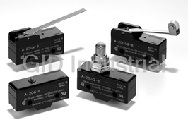
Omron A Series General Purpose Snap Action Switch
Part Number
A Series
Price
Request Quote
Manufacturer
OMRON
Lead Time
Request Quote
Category
PRODUCTS - A
Datasheet

Extracted Text
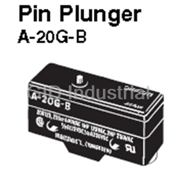
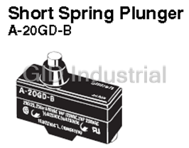
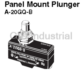
Snap Action Switch A General-purpose Snap Action Switch • High-capacity switch capable of handling 20 A loads with large inrush currents Directly switches such loads as motors, halogen lamps and solenoids Same shape as OMRON snap action switch model Z except in pin plunger position, yet endures inrush currents as large as 75 A. Ordering Information Terminal Solder terminal Screw terminal (-B) Actuator Model Model Pin plunger A-20G A-20G-B Short spring plunger A-20GD A-20GD-B Panel mount plunger A-20GQ A-20GQ-B Panel mount roller plunger A-20GQ22 A-20GQ22-B Panel mount cross roller plunger --- A-20GQ21-B Short hinge lever A-20GV21 A-20GV21-B Hinge lever A-20GV A-20GV-B Short hinge roller lever A-20GV22 A-20GV22-B Hinge roller lever A-20GV2 A-20GV2-B Model Number Legend A - 20 G - 1 2 3 4 3. Actuator 4. Terminals 1. Ratings None: Solder terminal 20: 20 A (250 VAC) None: Pin plunger B: Screw terminal D: Short spring plunger (with toothed washer) Q: Panel mount plunger 2. Contact Gap Q21: Panel mount cross roller plunger G: 0.5 mm Q22: Panel mount roller plunger V: Hinge lever V2: Hinge roller lever V21: Short hinge lever V22: Short hinge roller lever Snap Action Switch A 19 Specifications ■ Characteristics Operating speed 0.01 mm to 1m/s (see note 1) Operating frequency Mechanical 240 operations/min Electrical 20 operations/min Contact resistance 15 mΩ max. (initial value) Insulation resistance 100 MΩ min. (at 500 VDC) Dielectric strength 1,000 VAC, 50/60 Hz for 1 min between terminals of the same polarity 2,000 VAC, 50/60 Hz for 1 min between the current-carrying metal parts and the ground, and between each terminal and non-current-carrying metal parts Vibration resistance Malfunction 10 to 55 Hz, 1.5-mm double amplitude (See note 2) 2 Shock resistance Destruction max. 1,000 m/s 2 Malfunction 300 m/s max. (See notes 1 and 2) Degree of protection IP00 Degree of protection against electric shock Class I Proof tracking index (PTI) 175 Ambient operating temperature −25°C to 80°C (with no icing) Ambient operating humidity 35% to 85%RH Service life Mechanical 1,000,000 operations min. Electrical 500,000 operations min. Weight Approx. 22 to 58 g Note: 1. The value is for the pin plunger. 2. Malfunction: 1 ms max. ■ Operating Characteristics Characteristics A-20G-B A-20GD-B A-20GQ-B A-20GQ22-B A-20GQ21-B A-20GV21-B A-20GV-B A-20GV22-B A-20GV2-B OF 400 to 625 g 630 g max. 160 g 70 g 160 g 90 g RF min. 285 g 280g 42 g 14 g 42 g 14 g PT max. 1.3 mm 6.5 mm 15.9 mm 6.3 mm 12 mm OT min. 0.25 mm 3 mm 5.6 mm 3.58 mm 1.2 mm 4 mm 1.2 mm 2.4 mm MD max. 0.2 mm 0.35 mm 1.2 mm 2.4 mm 1.2 mm 2.2 mm OP 16.3±0.4 mm 26.2±0.5 mm 21.8±0.8 mm 33.4±1.2 mm 19±0.8 mm 19±0.8 mm 29.8±0.8 mm 30.2±0.8 mm ■ Ratings Non-inductive load (A) Inductive load (A) Rated voltage Resistive load Lamp load Inductive load Motor load (V) NC NO NC NO NC NO NC NO 125 VAC 20 7.5 20 12.5 250 VAC 20 7.5 20 8.3 500 VAC 15 4 10 2 8 VDC 20 3 1.5 20 12.5 14 VDC 20 3 1.5 15 12.5 30 VDC 6 3 1.5 5 5 125 VDC 0.5 0.5 0.5 0.05 0.05 250 VDC 0.25 0.25 0.25 0.03 0.03 Note: 1. The above values are for steady-state current. 4. Motor load has an inrush current of 6 times the steady-state current. 2. Inductive load has a power factor of 0.4 min. (AC) and a time 5. The ratings values apply under the following test conditions: constant of 7 ms max. (DC). (1) Ambient temperature: 20±2°C (2) Ambient humidity: 65±5%RH 3. Lamp load has an inrush current of 10 times the steady-state current. (3) Operating frequency: 20 operations/min ■ Contact Specification ■ Safety Standards Ratings UL/CSA (General ratings only) Contacts Shape Rivet Rated voltage A-20G Material Silver alloy 125 VAC 1 HP and 10 A "L" (Tungsten) Gap (standard value) 0.5 mm 250 VAC 2 HP Inrush current NC 75 A max. 480 VAC 20 A NO 75 A max. 125 VDC 0.5 A 250 VDC 0.25 A 20 Snap Action Switch A Engineering Data ■ Mechanical Durability (A-20G) ■ Electrical Durability (A-20G) 1,000 1,000 Ambient temperature: 20±2°C Ambient temperature: 20±2°C 700 Ambient humidity: 65±5%RH 700 Ambient humidity: 65±5%RH Without load Operating frequency: 500 500 Operating frequency: 20 operations/min 240 operations/min 300 300 125 VAC, cosφ = 1 125 VAC, cosφ = 0.4 250 VAC, cosφ = 1 100 100 70 70 50 50 250 VAC, cosφ = 0.4 30 30 10 10 0 0.1 0.2 0.3 0.4 0.5 0.6 0.7 0.8 052 10 15 205 Overtravel (mm) Switching current (A) ■ Structure Contact Form (SPDT) COM NC NO Dimensions Note: Unless otherwise specified, all units are in millimeters and a tolerance of ± 0.4 mm applies to all dimensions. ■ Terminals Screw Terminals (-B) Solder Terminal (Blank) 9.2 6.4 25.4±0.1 11.9 17.45±0.2 20 20 17.45±0.2 3 1 NO COM NO NC COM NC 2 13 2 Three, M4 × 5.5 49.2 Terminal screws 49.2 (with toothed washer) Note: Appropriate terminal screw tightening torque: 0.78 to 1.18 N·m. ■ Mounting Holes All switches can be mounted using M4 mounting screws with plane Versions with panel mount plungers can be panel mounted via the washers or spring washers to securely mount the Switch. Tighten the plunger, provided that the hexagonal nut of the actuator is tightened screws to a torque of 1.18 to 1.47 N·m. to a torque of 2.94 to 4.9 N·m. Two, 4.2 dia. mounting holes or M4 Panel Mount Plunger Panel Mount Roller Plunger + 0.2 +0.2 12.5 0 dia. 12.5 dia. 0 25.4±0.1 + 0.2 5 0 +0.2 13 0 Note: Mount using either the side mounting holes or the panel mount plunger, not both. If using the side mounting holes, then remove the hexagonal nut(s) from the panel mount plunger. Accessories (Terminal Covers, and Separators): Refer to ‘Z/A/X/DZ Common Accessories’ datasheet Snap Action Switch A 21 4 Durability (x10 operations) 4 Durability (x10 operations) Note: 1. All drawings show the switches with screw terminals. For solder terminals, remove the “-B” from the end of the part number 2. Unless otherwise specified, all units are in millimeters and a tolerance of ± 0.4 mm applies to all dimensions. 2.3 dia. 19.05±0.25 Pin Plunger PT +0.075 4.2 dia. hole −0.025 2.3SR * A-20G-B OP 24.2 9.2 +0.075 4.2 dia. −0.025 +0.1 4.36 dia. −0.05 11.9 17.45±0.2 25.4±0.1 * Stainless-steel plunger 49.2 15 dia. Short Spring Plunger 11.2 dia. A-20GD-B 19.05±0.25 7.15 PT 11.9SR * dia. 7.5 OP 24.2 * Stainless-steel plunger 8.35 dia. PT 19.05±0.25 Panel Mount Plunger 11.9SR *1 Note: Do not use both M12 M12 × 1 mounting screw mounting screw and A-20GQ-B mounting holes at the Two hexagon nuts OP same time. (2 t × 14 width across flats) *2 13.1 Two lock nuts (2 t × 15.6 width across flats) 16 dia. 16.3 *1 Stainless-steel plunger *2 Incomplete screw part with a maximum length of 1.5 mm. Panel Mount Roller Plunger 19.05±0.25 A-20GQ22-B PT 12.7 dia. × 4.8 *1 Two hexagon nuts (3 t × 17 width across flats) OP M12 × 1 mounting screw 15.5 *2 Note: Do not use both M12 mounting screw and mounting holes at the 16 dia. 16.3 same time. *1 Stainless-steel roller *2 Incomplete screw part with a maximum length of 1.5 mm. Panel Mount Cross Roller Plunger 19.05±0.25 A-20GQ21-B PT 12.7 dia. × 4.8 *1 Two hexagon nuts (3 t × 17 width across flats) OP M12 × 1 mounting screw 15.5 *2 Note: Do not use both M12 mounting screw and mounting holes at the 16 dia. 16.3 same time. *1 Stainless-steel roller *2 Incomplete screw part with a maximum length of 1.5 mm. 22 Snap Action Switch A Note: 1. All drawings show the switches with screw terminals. For solder terminals, remove the “-B” from the end of the part number 2. Unless otherwise specified, all units are in millimeters and a tolerance of ± 0.4 mm applies to all dimensions. Short Hinge Lever 24.56±0.25 A-20GV21-B t = 1 * 4.9 PT 20.2 17.9 OP 14.7 * Stainless-steel lever Hinge Lever 24.56±0.25 A-20GV-B 4.9 PT t = 1 * 20.2 17.9 OP 14.7 * Stainless-steel lever 24.56±0.25 9.5 dia. × 4 Short Hinge Roller Lever (plastic roller) t = 1 * A-20GV22-B PT OP 20.2 17.9 14.7 * Stainless-steel lever 9.5 dia. × 4 Hinge Roller Lever 24.56±0.25 (plastic roller) PT A-20GV2-B t = 1 * OP 20.2 17.9 14.7 * Stainless-steel lever Snap Action Switch A 23 63.5R 28.3R 48.4R 26.2R Safety Precautions Be sure to read the precautions and information common to all Snap Action and Detection Switches, contained in the Technical User’s Guide, “Snap Action Switches, Technical Information” for correct use. Do not use the switch in locations subject to hot water (greater than Precautions for Safe Use 60°C) or in water vapor. Terminal Connection Do not use the switch outside the specified temperature and When soldering lead wires to the Switch, make sure that the capacity atmospheric conditions. of the soldering iron is 60 W maximum. Do not take more than 5 s to The permissible ambient temperature depends on the model. solder any part of the Switch. The characteristics of the Switch will (Refer to the specifications in this catalog.) Sudden thermal deteriorate if a soldering iron with a capacity of more than 60 W is changes may cause thermal shock to distort the switch and result applied to any part of the Switch for 5 s or more. in faults. Operation Incorrect Correct Separate the installation lo-Make sure that the switching frequency or speed is within the cation from specified range. heat sources. 1. If the switching speed is extremely slow, the contact may not be switched smoothly, which may result in a contact failure or contact welding. 2. If the switching speed is extremely fast, switching shock may Mount a cover if the switch is to be installed in a location where damage the Switch soon. If the switching frequency is too high, worker inattention could result in incorrect operation or accidents. the contact may not catch up with the speed. The rated permissible switching speed and frequency indicate the Correct Incorrect switching reliability of the Switch. The life of a Switch is determined at the specified switching speed. The life varies with the switching speed and frequency even when they are within the permissible ranges. In order to determine the life of a Switch model to be applied to a particular (preventing malfunctions) use, it is best to conduct an appropriate durability test on some Subjecting the switch to continuous vibration or shock may result in samples of the model under actual conditions. contact failure or faulty operation due to abrasion powder and in Make sure that the actuator travel does not exceed the permissible reduced durability. Excessive vibration or shock will cause the OT position. The operating stroke must be set to 70% to 100% of contacts to operate malfunction or become damaged. Mount the the rated OT. switch in a location that is not subject to vibration or shock and in a direction that does not subject the switch to resonance. Precautions for Correct Use If silver contacts are used with relatively low frequency for a long Mounting Location time or are used with microloads, the sulfide coating produced on Do not use the switch alone in atmospheres such as flammable or the contact surface will not be broken down and contact faults will explosive gases. Arcing and heat generation associated with result. Use a microload switch that uses gold contacts. switching may cause fires or explosions.Do not use the switch in atmospheres with high humidity or heat or Switches are generally not constructed with resistance against in harmful gases, such as sulfide gas (H S, SO ), ammonia gas 2 2 water. Use a protective cover to prevent direct spraying if the switch (NH ), nitric acid gas (HNO ), or chlorine gas (Cl ). Doing so may 3 3 2 is used in locations subject to splashing or spurting oil or water, impair functionality, such as with damage due to contacting faults or dust adhering. corrosion. The switch includes contacts. If the switch is used in an atmosphere Incorrect Correct with silicon gas, arc energy may cause silicon oxide (SiO ) to 2 accumulate on the contacts and result in contact failure. If there is silicon oil, silicon filling, silicon wiring, or other silicon products in the vicinity of the switch, use a contact protection circuit to limit arcing and remove the source of the silicon gas. Terminal box Panel-mounting model (A-20GQ@) Terminal box If a Switch is side-mounted with screws, remove the hexagonal nut Install the switch in a location that is not directly subject to debris of the actuator. and dust from cutting. The actuator and the switch body must be If a Switch is side-mounted and secured with screws, make sure protected from accumulated cutting debris and dirt. that the angle or speed of the actuating object is not excessively large or too high, otherwise the Switch may be damaged. Incorrect Correct If a Switch is panel-mounted, pay utmost attention to make sure that the actuating speed or OT distance is not excessively high or large. Not doing so may damage the Switch. 24 Snap Action Switch A MEMO Snap Action Switch A All sales are subject to Omron Electronic Components LLC standard terms and conditions of sale, which can be found at http://www.components.omron.com/components/web/webfiles.nsf/sales_terms.html ALL DIMENSIONS SHOWN ARE IN MILLIMETERS. To convert millimeters into inches, multiply by 0.03937. To convert grams into ounces, multiply by 0.03527. OMRON ON-LINE OMRON ELECTRONIC COMPONENTS LLC Global - http://www.omron.com 55 E. Commerce Drive, Suite B USA - http://www.components.omron.com Schaumburg, IL 60173 847-882-2288 Cat. No. X303-E-1 11/10 Specifications subject to change without notice Printed in USA Snap Action Switch A
Frequently asked questions
What makes Elite.Parts unique?

What kind of warranty will the A Series have?
Which carriers does Elite.Parts work with?
Will Elite.Parts sell to me even though I live outside the USA?
I have a preferred payment method. Will Elite.Parts accept it?


What they say about us
FANTASTIC RESOURCE
One of our top priorities is maintaining our business with precision, and we are constantly looking for affiliates that can help us achieve our goal. With the aid of GID Industrial, our obsolete product management has never been more efficient. They have been a great resource to our company, and have quickly become a go-to supplier on our list!
Bucher Emhart Glass
EXCELLENT SERVICE
With our strict fundamentals and high expectations, we were surprised when we came across GID Industrial and their competitive pricing. When we approached them with our issue, they were incredibly confident in being able to provide us with a seamless solution at the best price for us. GID Industrial quickly understood our needs and provided us with excellent service, as well as fully tested product to ensure what we received would be the right fit for our company.
Fuji
HARD TO FIND A BETTER PROVIDER
Our company provides services to aid in the manufacture of technological products, such as semiconductors and flat panel displays, and often searching for distributors of obsolete product we require can waste time and money. Finding GID Industrial proved to be a great asset to our company, with cost effective solutions and superior knowledge on all of their materials, it’d be hard to find a better provider of obsolete or hard to find products.
Applied Materials
CONSISTENTLY DELIVERS QUALITY SOLUTIONS
Over the years, the equipment used in our company becomes discontinued, but they’re still of great use to us and our customers. Once these products are no longer available through the manufacturer, finding a reliable, quick supplier is a necessity, and luckily for us, GID Industrial has provided the most trustworthy, quality solutions to our obsolete component needs.
Nidec Vamco
TERRIFIC RESOURCE
This company has been a terrific help to us (I work for Trican Well Service) in sourcing the Micron Ram Memory we needed for our Siemens computers. Great service! And great pricing! I know when the product is shipping and when it will arrive, all the way through the ordering process.
Trican Well Service
GO TO SOURCE
When I can't find an obsolete part, I first call GID and they'll come up with my parts every time. Great customer service and follow up as well. Scott emails me from time to time to touch base and see if we're having trouble finding something.....which is often with our 25 yr old equipment.
ConAgra Foods