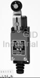
VL (AZ8)
COMPACT SIZE
LIMIT SWITCHES
Limit Switches
A compact and accurate vertical limit switch. Switches with indicator lamp available for
convenient maintenance; either a neon AC powered lamp or an LED DC powered lamp.
of the lamp holder attachment, it is
Inner construction
possible to display both lights during
Cover
attachment screw
inoperability and during operation
(however, if both NO and NC loads are
connected, only the inoperability lamp
Cable
Cover
can be displayed.)
Cord vent
Terminal screw
Construction permits lamp attach-
ment method to be changed.
Body
Operating lamp Inoperability lamp
Head block
(with output)
4. Mounting is possible from both
front and back
Standard type With lamp
(Roller arm)
M4 attachment nut
• Lead wiring type
Characteristics
(LED lamp type only)
1. Compact design approximately
Because the wiring can be made par-
1/3 of the AZ5 limit switches
allel to the load, current leakage from
Spring washer
the lamp can be reduced to 0. Even
with a slight leak, the electronic circuit
Approx. 1/3
incurring the leak can be used safely.
7. Dust-proof, waterproof, oil resis-
M5 attachment bolt
r
tant construction
The main unit and the cover are
sealed with rubber packing, and the
AZ5 type VL
cord runner is doubly sealed by the
2. Gold-clad contacts provide reli-
cord vent. The actuator is sealed by
able operation in low voltage cir-
Spring washer
both a rubber cap and an O ring in all
cuits. Design minimizes contact
models. Also, the lens and cover are
chatter and bounce
5. Lamp type switches can be used
formed simultaneously with the lamp
The built-in switch has gold-clad con-
with a wide range of voltages
type, and moreover, a nameplate is
tacts and uses a crossbar contact
• With neon lamp
affixed to the upper surface, thereby
method for excellent reliability. It also
Compatible with: AC100 and 200V ;
improving the already excellent water-
has a dual cutoff circuit (1a1b contact)
Even at AC 100V, sufficient luminosity
proof capabilities.
with little chattering and bouncing due
is achieved through the diamond-cut
(Note: Applications directly involving
to computer-operated analysis.
lens. The lamp has a long lifespan of
the cord entrance and the locations
3. Easy wiring with full-open terminals
more than 20 thousand hours.
which are always wet and oily, or sub-
When the cover is removed, the termi-
• With LED lamp
mersion in water or oil, cannot be
nals are fully accessible. Moreover, the
Covers 6 to 48V DC and comes in
used.)
wiring space is large despite the com-
three types, 6V DC , 12V DC ,
pact size, and the terminals are spread
24 to 48V DC Uses two highly lumi-
TYPICAL
in a tiered array, so that wiring work
nescent LEDs and a diamond-cut lens.
can be completed very easily.
6. Lamp connection can be either
APPLICATIONS
The cable can either be screwed in
spring type or lead wire type
Ideal for general plant facilities such as
directly, or can use U-shaped and cir-
• Spring type (wiring unnecessary)
engineering machinery, conveyer
cular pressure terminals.
(With neon or LED lamp type)
machinery, and assembly lines
Wiring is unnecessary because the
LED lamp type is also compatible with
U
® L lamp is directly connected to the termi-
low-voltage DC control circuits such as
nals. By simply changing the direction
in PCs and computers.
431
VL (AZ8)
PRODUCT TYPE
1. Standard type
Actuator Part No.
Push plunger AZ8111
Roller plunger AZ8112
Cross roller plunger AZ8122
Roller arm AZ8104
Adjustable roller arm AZ8108
Adjustable rod AZ8107
Flexible rod AZ8166
Spring wire AZ8169
Remote wire control plunger AZ8181
Note) When ordering an overseas-specified product,refer to the Overseas Standards given below.
2. With Neon lamp
Lamp connection Actuator Lamp rating Part No.
Push plunger AZ811106
Roller plunger AZ811206
Cross roller plunger AZ812206
Roller arm AZ810406
Spring type Adjustable roller arm 100 to 200V AC AZ810806
Adjustable rod AZ810706
Flexible rod AZ816606
Spring wire AZ816906
Remote wire control plunger AZ818106
Note) When ordering an overseas-specified product,refer to the Overseas Standards given below.
3. With LED
Lamp rating
Lamp connection Actuator 12V DC 24 to 48V DC
Part No.
Push plunger AZ8111161 AZ811116
Roller plunger AZ8112161 AZ811216
Cross roller plunger AZ8122161 AZ812216
Roller arm AZ8104161 AZ810416
Spring type Adjustable roller arm AZ8108161 AZ810816
Adjustable rod AZ8107161 AZ810716
Flexible rod AZ8166161 AZ816616
Spring wire AZ8169161 AZ816916
Remote wire control plunger AZ8181161 AZ818116
Push plunger AZ8111661 AZ811166
Roller plunger AZ81122661 AZ811266
Cross roller plunger AZ8122661 AZ812266
Roller arm AZ8104661 AZ810466
Lead wire type Adjustable roller arm AZ8108661 AZ810866
Adjustable rod AZ8107661 AZ810766
Flexible rod AZ8166661 AZ816666
Spring wire AZ8169661 AZ816966
Remote wire control plunger AZ8181661 AZ818166
Notes)1. LED rating 6V DC type is available. When ordering, add suffix 162(spring type) or 662(lead wire type) to the standard part No.
2.The DC24-48V rated lamp is recommended for PC input use.
4. Option
Application Part No.
VL limit conduit adapter VL, VL with lamp, VL-T AZ8801
STANDARDS
Standard Applicable product Part No.
File No. : E122222
Ratings : 5A 250V AC
UL
Pilot duty B300
Order by standard part No. However,
Product type : Standard model, with neon lamp
add “9” to the end of the part No. for the
model with neon lamp.
File No. : LR55880
Ratings : 5A 250V AC
CSA
Pilot duty B300
Product type : Standard model, with neon lamp
File No. : J9551203
TÜV Ratings : AC-15 2A/250V upwards Order by standard part No.
Product type : Standard model only
432
VL (AZ8)
SPECIFICATIONS
1. Contact Rating
1) Standard type 2) Type with indicator
Load
Resistive load Inductive load Rated control Resistive load Inductive load
Types
(cos f]1) (cos f]0.4) (cos f]1) (cos f]0.4)
Rated control voltage voltage
125V AC 5A 3A 125V AC 5A 3A
With Neon lamp
250V AC 5A 2A 240V AC 5A 2A
125V DC 0.4A 0.1A With LED 24V DC 3A –
2. Contact Characteristics
Contact arrangement 1 Form Z
Initial contact resistance, max. 15mΩ (By voltage drop 6 to 8V DC at rated current)
Contact material Gold clad over silver
Initial insulation resistance (At 500V DC) Min. 100MΩ
1,000Vrms for 1 min Between non-consective terminals 2,000Vrms for 1 min Between
Initial breakdown voltage
dead metal parts and each terminal 2,000Vrms for 1 min Between ground and each terminal
2
In the free position Max. 98m/s {10G}
Shock resistance max.
2
In the full operating position Max. 294m/s {30G}
Vibration resistance Standard type: Max. 55Hz Type with indicator: 10 to 50Hz, double amplitude of 1.5mm
7
Mechanical 10 (at 120 cpm)
5 6
Expected life (Min. operations) Electrical 3u10 (at rated resistive load) 5u10 (Magnetic contactor FC-100 200V AC load)
4
Life of lamp Min. 2u10 hours (Neon lamp type)
Ambient temperature/Ambient humidity –20 to +60°C –4 to +140°F/Max. 95%
Max. operating speed 120 cpm
3. EN60947-5-1 performance
Item Rating
Rated insulation voltage (Ui) 250VAC
Rated impulse withstand voltage (Uimp) 2.5kV
Switching overvoltage 2.5kV
Rated enclosed thermal current (Ithe)
5A
Conditional short-circuit current
100A
Short-circuit protection device
10A fuse
Protective construction
IP64
Pollution degree
3
4. Operating characteristics
Characteristics
Pretravel (P.T.), max. Movement Differential Overtravel (O.T.), min. Totaltravel (T.T.),
O.F. (N {gf}) max. R.F. (N {gf}) min.
mm inch (M.D.), max. mm inch mm inch min. mm inch
Actuator
Push plunger
Roller plunger 8.83 {900} 1.47 {150} 1.5 .059 0.7 .028 4 .028 5.5 .217
Cross roller plunger
Roller arm 5.88 {600} 0.49 {50} 20° 10° 75° 95°
Adjustable roller arm 7.84 {800}~3.35 {342} 0.49 {50}~0.21 {21} 20° 10° 75° 95°
Adjustable rod 7.84 {800}~1.99 {203} 0.49 {50}~0.12 {12} 20° 10° 75° 95°
Flexible spring wire 0.88 {90} – 30 (1.181) – 20 (.787) 50 (1.969)
Remote wire control 19.61 {2,000}~ 1.96 {200}~
1.5 .059 4 .157* 0.7 .028 2.0 .079* 4.5 .177 2.0 .079* 6 .236 6 .236*
plunger 24.52 {2,500}* 1.96 {200}*
*Characteristics measured at bent condition: min. radius 100mm 3.937inch.
Notes) 1. Keep the total travel values in the specified range. Otherwise the actuator force may rise to several times the operating force, resulting in a mechanical failure or much shorter service life.
2. For the operating characteristics, refer to the TECHNICAL INFORMATION.
5. Protective construction 6.Lamp rating
Protective construction Types Rated operating voltage Operating voltage range Internal resister
VL mini limit SW
VL mini limit SW
(with indicator)
IEC Neon lamp 100 to 200V AC 80 to 240V AC 120kΩ
IP60 p p 6V DC 5 to 15V DC 2.4kΩ
IP64 p p LED 12V DC 9 to 28V DC 4.7kΩ
24 to 48V DC 20 to 55V DC 15kΩ
DATA WIRING DIAGRAM
1. Life curve
2. Actual load life curve (relay coil load)
VL
Output
13 14
, 1000 NO NO
Life curve resistive load
circuit
( )
AC 240VC cos =1 φ 11 12
1000
NC NC
500 500
Terminal
400
300 13 14
0 0.5 1.0 3 5 50 260 700
200
NK HC HPHG VC-20 FC-10 FC-35 FC-100
Various relay loads (VA)
100
30
Note: The FC magnetic contactor series is 200V AC. The K is
0 5 10
2 Form C 24V DC type.
11 12
Load current, A
433
,
No. of operating million times
No. of operating, million times
VL (AZ8)
mm inch
10.2 10.2
7 .276 dia.
DIMENSIONS
.402 .402
stainless steel plunger 3
.118
General
PT 1.5max
• Push plunger type
tolerance:
+0.2
2-4.1 0 dia.
4 4
mounting holes 26.5
Standard type
.157 .157 ±0.4
1.043
M326 ( )
2-M5 P=0.8 tapped ( )
2-M5 P=0.8
20.4–0.3
cover screw 7 .276 in depth
7 .276 in depth
.803–.012
mounting holes
mounting holes
56–0.3 64 64
2.205–.012 2.520 2.520
Operation indicator
( ) 2-M5 (P=0.8)
2-M5 P=0.8 tapped
mounting holes mounting holes
2-M3223
cover screw
14 14
.551 .551
7.5–0.2 7.5–0.2
21–0.2
.295–.008 .295–.008
15.1 15.1
.827–.008
.594 .594
28 20.4–0.3
25
1.102 .803–.012
.984 30.3
1.193
(Standard type) (With Neon lamp)
12.5 dia.23.8
10.2 10.2
• Roller plunger type
stainless steel roller
.402 .402
General
PT 1.5max
Standard type tolerance:
14.8
.583
±0.4
+0.2
38
2-4.1 dia.
0
4 4
1.496
mounting holes
.157 .157
M326
( ) ( )
2-M5 P=0.8 tapped 2-M5 P=0.8
20.4–0.3
cover screw
7 .276 in depth 7 .276 in depth
.803–.012
mounting holes mounting holes
56–0.3 64 64
2.205–.012 2.520 2.520
Operation indicator
( ) ( )
2-M5 P=0.8 tapped 2-M5 P=0.8
mounting holes mounting holes
2-M3223
cover screw
14 14
.551 .551
7.5–0.2 7.5–0.2
21–0.2
.295–.008 .295–.008
15.1 15.1
.827–.008
.594 .594
28 20.4–0.3
25
1.102 .803–.012
30.3
.984
1.193
(Standard type) (With Neon lamp)
12.5 dia.23.8 10.2 10.2
• Cross roller plunger type
General
stainless steel roller .402 .402
PT 1.5max
tolerance:
Standard type
14.8 ±0.4
.583
+0.2
38
2-4.1 0 dia.
1.496 4 4
mounting holes
.157 .157
M326
2-M5 (P=0.8) tapped 2-M5 (P=0.8)
20.4–0.3
cover screw
.803–.012 7 .276 in depth 7 .276 in depth
mounting holes mounting holes
56–0.3 64 64
2.205–.012 2.520 2.520
Operation indicator
( ) ( )
2-M5 P=0.8 tapped 2-M5 P=0.8
mounting holes mounting holes
2-M3223
cover screw
14 14
.551 .551
7.5–0.2 7.5–0.2
21–0.2
.295–.008 .295–.008
15.1 15.1
.827–.008
.594 .594
28 20.4–0.3
25
1.102 .803–.012
30.3
.984
1.193
( ) ( )
Standard type With Neon lamp
18 dia.27
41.2–0.8 45.2–0.8
nylon roller
• Roller arm type
1.622–.031 1.780–.031 General
(
Roller can be rotated
36.2–0.8 40.2–0.8
and locked in any
1.425–.031 1.583–.031
) tolerance:
position through 360°
Standard type
±0.4
10.2 10.2
.402 .402
M4 arm
M4 arm fixing nut
fixing screw
+0.2
(
2-4.1 0 dia. with hexagonal
)
mounting holes holes 2-M5 (P=0.8) tapped 2-M5 (P=0.8)
18.5 18.5
.728 7 .276 in depth .728 7 .276 in depth
12.5
mounting holes mounting holes
.492
M326 20.4–0.3
cover screw .803–.012
56–0.3 64 64
2.205–.012 2.520 2.520
Operation indicator
( ) ( )
2-M5 P=0.8 tapped 2-M5 P=0.8
mounting holes mounting holes
2-M3223
cover screw
14 14
.551 .551
7.5–0.2 7.5–0.2
21–0.2
.295–.008 .295–.008
15.1 15.1
.827–.008
.594 .594
28 25 20.4–0.3
1.102 .984 Standard type .803–.012 With lamp
38.1 30.3
1.5 1.193
( ) ( )
434
x
a
m
0°
2
T
P
R30
x
VL (AZ8)
( ) ( )
• Adjustable rod type 44.9 44.9
mm inch
5.5 ( ) ( )
1.768 1.768
.217
36.3–0.8 36.3–0.8
1.429–.031 1.429–.031
Standard type
General
2.6 .102 dia. rod
(Roller can be rotated
and locked in any tolerance:
position through 360°)
±0.4
M4 rod fastening plate
10.2 10.2
screw with hexagonal holes
.402 .402
Adjustable lenght of rod
(30-118)
Rod fastening plate
+0.2
2-4.1 0 dia.
18.5
mounting holes 18.5
Rod mounting metal Rod mounting metal
.728 .728
12.5
.492
M6 mounting rod M6 mounting rod
fastening screw with fastening screw with
hexagonal holes hexagonal holes
M326
2-M5 (P=0.8)
cover screw
7 .276 in depth
mounting holes
64
56–0.3 64 2-M5 (P=0.8) tapped
2.205–.012 2.520 2.520
7 .276 in depth
mounting holes
Operation indicator
( ) ( )
2-M5 P=0.8 tapped 2-M5 P=0.8
mounting holes mounting holes
2-M3223
cover screw
14 14
.551 .551
7.5–0.2 7.5–0.2
21–0.2
.295–.008 .295–.008
15.1 15.1
.827–.008
.594 .594
28 20.4–0.3 20.4–0.3
.803–.012
1.102 .803–.012
25 30.3
.984 1.193
(44.9) (1.768) (44.9) (1.768)
(Standard type) (With Neon lamp)
• Adjustable roller arm type
(Length of arm can be adjustable within 30 to 70mm 1.181 to 2.756inch by 1mm .039inch pitch)
47.7–0.8 47.7–0.8
Standard type
1.878–.031 1.878–.031
42.7–0.8 42.7–0.8
1.681–.031 1.681–.031
18 dia.27 nylon roller
33.5–0.8 33.5–0.8
Adjustable lenght of arm (
Roller can be rotated 1.319–.031 1.319–.031
( ) General
30-70
and locked in any
28.5–0.8 28.5–0.8
position through 360°)
1.122–.031 1.122–.031
tolerance:
M4 arm fastening
plate screw with
±0.4
hexagonal holes
10.2 10.2
.402 .402
Arm fastening plate
+0.2
2-4.1 0 dia. 18.5 18.5
mounting holes Mounting metal .728 Mounting metal .728
12.5
.492
M6 arm fastening M6 arm fastening
plate screw with plate screw with
M326 hexagonal holes hexagonal holes
2-M5 (P=0.8)
cover screw
7 .276 in depth
mounting holes
56–0.3 64 64
2-M5 (P=0.8) tapped
2.205–.012 2.520 2.520
7 .276 in depth
Operation indicator mounting holes
2.0 2-M5 (P=0.8) tapped 2.0 2-M5 (P=0.8)
.079 .079
mounting holes mounting holes
2-M3223
cover screw
14 14
.551 .551
7.5–0.2 7.5–0.2
21–0.2
.295–.008 .295–.008
15.1 15.1
.827–.008
.594 .594
28 20.4–0.3 20.4–0.3
1.102 .803–.012 .803–.012
25 30.3
.984 1.193
( ) ( ) ( ) ( )
46.4 1.827 ( ) 46.4 1.827 ( )
Standard type With Neon lamp
• Flexible rod type
(Should be used with less than 50mm 1.969inch of T.T.)
General
10.2 10.2
tolerance:
PT 50 max .402 .402
Standard type
3 dia. 3 dia.
±0.4
.118 .118
Nylon rod Nylon rod
41.5
1.634
5.8 dia. 5.8 dia.
.228 .228
100–1.5
3.937–.059
+0.2
2-4.1 0 dia.
4 4
mounting holes
.157 .157
M326
2-M5 (P=0.8) tapped 2-M5 (P=0.8)
cover screw 20.4–0.3
7 .276 in depth 7 .276 in depth
.803–.012
mounting holes mounting holes
56–0.3 64 64
2.205–.012 2.520 2.520
Operation indicator
2-M5 (P=0.8) tapped 2-M5 (P=0.8)
mounting holes mounting holes
2-M3223
cover screw
14 14
.551 .551
7.5–0.2 7.5–0.2
21–0.2
.295–.008 .295–.008
15.1 15.1
.827–.008
.594 .594
28 20.4–0.3
25
1.102 .803–.012
30.3
.984
1.193
( ) ( )
Standard type With Neon lamp
435
x
a
a
m
m
0°
0°
2
2
T
T
P
P
VL (AZ8)
• Spring wire type(Should be used with less than 50mm 1.969inch of T.T.) General tolerance: ±0.4 ±.016
Standard type
10.2 10.2
PT 30 max .402 .402
1.2 dia. 1.2 dia.
.047 stainless .047 stainless
steel wire steel wire
51.5
2.028
100–1.5
3.937–.059
+0.2
2-4.1 0 dia.
4 4
mounting holes
.157 .157
M326
( ) ( )
2-M5 P=0.8 tapped 2-M5 P=0.8
cover screw 20.4–0.3
7 .276 in depth 7 .276 in depth
.803–.012
mounting holes mounting holes
56–0.3 64
2.205–.012 2.520
64
Operation indicator 2.520
( ) ( )
2-M5 P=0.8 tapped 2-M5 P=0.8
mounting holes mounting holes
2-M3223
cover screw 14 14
.551 .551
7.5–0.2 7.5–0.2
21–0.2
.295–.008 .295–.008
15.1 15.1
.827–.008
.594 .594
28 20.4–0.3
25
1.102 .803–.012
30.3
.984
1.193
( ) ( )
Standard type With Neon lamp
• Remote wire control type ( ) General tolerance: ±0.4 ±.016
M12 P=1.25 Panel mounting nut and washer
1000–5
39.37–.197
( )
7 63
M10 operation adjustment nut
.276 (2.480)
Bending radius to be over 100mm 3.937inch
7
Wrench groove
PT 1.5max
.276 for operation
∗)(PT 4max)
10.2 10.2
adjustment
.402 .402
( )
M12 P=1.25
7 .276 dia. plunger
( )
+0.2 40
2-4.1 0 dia.
(1.575)
4 4
mounting holes
.157 .157
M326
2-M5 (P=0.8) tapped 2-M5 (P=0.8)
cover screw
20.4–0.3
7 .276 in depth 7 .276 in depth
.803–.012
mounting holes mounting holes
56–0.3 64 64
2.205–.012 2.520 2.520
Operation indicator
2-M5 (P=0.8) tapped 2-M5 (P=0.8)
mounting holes mounting holes
2-M3223
cover screw
14 14
.551 .551
7.5–0.2 7.5–0.2
21–0.2
.295–.008 .295–.008
15.1 15.1
.827–.008
.594 .594
28 20.4–0.3
25
1.102 .803–.012
30.3
.984
∗) 1.193
100 mm 3.937inch and the total bend comes to 360°
( ) ( )
Standard type With Neon lamp
1. Mounting 2) When the wire is bent, the radius
1) Fasten a switch body should be a minimum of 100mm
2) Temporarily fasten a wire 3.937inch.
3) Fasten an actuator 3) When fastening the wire to a support
4) Permanently fasten the wire when surface locate the fasteners at least
adjustment is complete 100mm 3.937inch from the end of the
Note) When setting the operating position, it is rec-
wire as shown below:
ommended to adjust operation adjustment nut
to keep safety margin for releasing.
2. Actuator
100mm 100mm
1) Make a hole (12.5±0.3mm
3.937 inch 3.937 inch
.492±.012inch dia.) on the panel.
4) Use the least number of fastening points
2) Fasten the actuator with a panel
possible.
mounting nut
5) When the wire is fastened, use the
and washer. 12.5–0.3 dia.
.492–.012 rubber bushing to avoid a change in
3. Remote wire
the diameter.
1) Use the wire in
6) When the wire is bent, P.T., M.D. and
as straight a
O.T. can be adjustable as below;
configuration
P.T. = 2.5mm .098inch (max.)
as possible.
M.D. = 1.5mm .059inch (max.)
Panel thickness max. 10mm .394 inch
O.T. = 3.5mm .138inch (min.)
436
VL (AZ8)
mm inch
OPTION
(A set of mounting hex.
t=7 max.
VL Conduit Adapter
socket screws is supplied.)
.276
AZ8801
56
• Applicable wire
13/64
(
Same as with the
)
VL limit switch
Electric wire name Finished outside diameter
Vinyl cabtire cord (VCTF)
8.7 to 11 dia. 23
18
.906
.343 to .433 dia. .709
Part A
Vinyl cabtire cable (VCT)
(
Tighten up
)
with no gap
14.8
21
.827 .583
28 27.8
1.102 1.094
(
Same as with the
)
VL limit switch
( ) ( )
Front Side
INDICATOR LIGHTING CIRCUIT
1. Spring type
1) When connecting a load to the N.O. 2) When connecting a load to the N.C. 3) When connecting loads to both N.O.
side: side: and N.C. sides:
When the switch is in the free position, When the switch is in the free position, Same as in 1).
the indicator is lit. When the switch the indicator is off. When the switch (With the lamp holder in the same
operates, the indicator turns off. (With operates, the indicator turns on. position as shipped from the factory. In
the indicator holder in the same posi- (With the lamp holder position this case, the holder position cannot
tion as shipped from the factory.) changed by 180° from the factory set be changed.)
position.)
(With Neon lamp) (With Neon lamp) (With Neon lamp)
(With LED) (With LED) (With LED)
LED Resistor
LED Resistor (With Neon lamp) Neon lamp Resistor
(With Neon lamp)
Built-in switch
Built-in switch
Neon lamp Resistor 13 14
Load
N.O.
13 14
N.O.
13 14 N.O.
3 4 N.C.
N.O. Load N.O.
N.C.
13 14
N.O. Load Load
Load
11 12
13 14
N.C. 11 12
N.C.
Built-in switch N.C.
11 12 Load
Resistor 1 2
Load
N.C.
Built-in switch 11 12
AC power source
11 12 Neon lamp
AC power source
AC power source Built-in switch
Built-in switch
Resistor
LED
– +
– + – +
DC power source DC power source DC power source
2. Lead wire type (only for switches with 2) When the indication circuit is con-
LED
LED) nected with load in parallel:
1) When giving indication on N.O. side Load performs the same operation as
or N.C. side, operation is the same as the indication circuit does.
N.O.
13 14
Load
for the spring type. However, when the (When load operates, the lamp is lit,
Resistor
load is connected to both the N.O. side and when load is turned off, the lamp N.C.
11 12
and N.C. side, indication can be given goes out.)
Built-in switch
on both N.C. side and N.O. side. • More loads than for one circuit can-
not be controlled.
– +
• There is no leakage current.
DC power source
mm inch
MOUNTING DIMENSIONS
Surface mounting Through hole mounting Rear mounting
t
4 .157 tap
5 .197 mounting screw
mounting nut
(P=0.7)
4 .157
4 .157 dia.
4-5.5 .217 dia.
4 .157
mouting screw
mounting screw
56–0.2
56–0.3
56–0.3
2.205–.008
2.205–.012
2.205–.012
21–0.2
washer
21–0.3 21–0.3
washer
.827–.008 washer
.827–.012 .827–.012
Depth of screw holes > 15mm .591inch Thickness of panel < 5mm .197inch Length of bolt < panel thickness t+7mm
437
~
~
~
VL (AZ8)
Cable treatment
WIRING mm inch
Applicable fasten terminal
Ordinary termi-
-Insulation distance more than Max. 6.4 .252 Max. 6.4 .252 Max. 6.4 .252
3.0 to 3.7 dia. N.C. use N.O. use
6.4mm .252inch for wiring and live
.118 to .146
9 .354
parts
9 .354
27 1.063
3.0 to 3.7 dia. 3.0 to 3.7 dia.
11 .433
Max. 10 Max. 10
-Special assembly screws
.118 to .146 .118 to .146
.394 .394
With insulated grip Fasten terminal
N.C. use N.O. use
Max. 6.4 .252 Max. 6.4 .252 Max. 6.4 .252
Terminal
( )
Projection 8 locations
screw
3.0 to 3.7 dia.
32 1.260
.118 to .146
( )
Groove 8 points 16 .630
3.0 to 3.7 dia. 3.0 to 3.7 dia.
( )
Spring 4 locations
.118 to .146 .118 to .146
Max. 14
Max. 14 Max. 10
Terminal
.551 .551 .394
washer
Grounding terminal
Applicable wire Head direction change
(Roller arm, adjustable roller arm, adjustable rod types)
Applicable wire
Wire name
Actuator heads
Wire-strand Conductor Finished outside diameter
( )
Lock screw Black
2 2
may be moved in
2-wire 0.75mm •1.25mm
2
Vinyl cabtire cord (VCTF) 3-wire 2.0mm
90° increments to
2 2 Round shape
4-wire 0.75mm •1.25mm
any of four direc-
6 dia. to 9 dia.
2
Vinyl cabtire cable (VCT) 2-wire 0.75mm
tions, by removing
Flat shape Max. 9.4
1.0 dia. to 1.2 dia.
600V vinyl insulation sealed
one screw.
2-wire
cable (VVF)
1.6 dia.
5. Remote wire control types (fig. 1):
CAUTIONS
Because the main unit is not of water
1. When overtravel is too large, life is
resistant or immersion-proof construc-
shortened due to possible damage to the
tion, their use in water or oil should be
mechanism. Please use in the following
avoided. Also, locations where water or
appropriate range.
oil can normally impinge upon the switch Driver
or where there is an excessive accumu-
Types Overtravel
Spring
Lamp
lation of dust should be avoided. The
Plunger 1.5 to 2.0mm
holder
(AZ8111, 8112, 8122) .059 to .079inch
Cover
main unit should be installed above the
Roller Arm
detection part in such case. (An actuator
20 to 30°
(AZ8104, 8107, 8108)
is immersion-protected construction.)
Flexible Rod 15 to 20mm .591 to
fig. 2
(AZ8166, 8169) .787inch (at the top) 6. Mounting
Three cover screws should be fastened
2. Because these switches are not of
uniformly. The rubber for opening cord
8. Matters to be attended to in using
immersion protected construction, their
should be corrected as normal condition
spring type VL Limit Switch with indica-
use in water or oil should be avoided.
after connecting the wire.
tor.
Also, locations where water or oil can
7. How to change the indicator holder.
1) When loads are connected to both
normally impinge upon the switch or
1) As shown in the photograph (fig. 2),
N.O. and N.C. only the indicatin at non-
where there is an excessive accumula-
insert a flatblade screw driver in the gap
operation time can be used.
tion of dust should be avoided.
between the cover and the part of the
2) Take special care not to damage or
3. The use of these switches under the
indicator holder indicated by the arrow in
deform the contact spring during change
following conditions should be avoided. If
the direction of insertion, and raise the
of indicator holder direction or during
the following conditions should become
lamp a little.
connection work.
necessary, we recommend consulting us
2) After removing the indicator holder,
3) In the case of VL Limit Switch with
first.
insert it in the reverse direction, and
Neon lamp, if the indicator is connected
• Use where there will be direct contact
push it in until a snap is heard.
in series in a 100V circuit, the indicator
with organic solvents, strong acids or
3) After changing the direction of the
ceases to be lighted.
alkalis, or direct exposure to their vapors.
indicator holder, put the cover on it in
However, for a 200V circuit, up to 2
• Use where inflammable or corrosive
such a way that the spring touches the
lamps can be connected in series.
gases exist.
top of the terminal screw.
9. Matters to be attended to in using lead
4. In order to maintain the reliability at a
(Unless the spring rests completely on
wire type VL with lamp.
high level under practical conditions of
the terminal screw, distortion of the
1) When loads are connected to both
use, the actual operating conditions
spring, failure in lighting of the lamp or
N.O. and N.C. indication can be given on
should be checked for the benefit of the
short circuit may result.)
both N.O. and N.C. sides, but it is impos-
quality of the product.
sible to connect the indication circuit to
the load in series.
Detected object
fig. 1
438


 Manufacturers


What they say about us
FANTASTIC RESOURCE
One of our top priorities is maintaining our business with precision, and we are constantly looking for affiliates that can help us achieve our goal. With the aid of GID Industrial, our obsolete product management has never been more efficient. They have been a great resource to our company, and have quickly become a go-to supplier on our list!
Bucher Emhart Glass
EXCELLENT SERVICE
With our strict fundamentals and high expectations, we were surprised when we came across GID Industrial and their competitive pricing. When we approached them with our issue, they were incredibly confident in being able to provide us with a seamless solution at the best price for us. GID Industrial quickly understood our needs and provided us with excellent service, as well as fully tested product to ensure what we received would be the right fit for our company.
Fuji
HARD TO FIND A BETTER PROVIDER
Our company provides services to aid in the manufacture of technological products, such as semiconductors and flat panel displays, and often searching for distributors of obsolete product we require can waste time and money. Finding GID Industrial proved to be a great asset to our company, with cost effective solutions and superior knowledge on all of their materials, it’d be hard to find a better provider of obsolete or hard to find products.
Applied Materials
CONSISTENTLY DELIVERS QUALITY SOLUTIONS
Over the years, the equipment used in our company becomes discontinued, but they’re still of great use to us and our customers. Once these products are no longer available through the manufacturer, finding a reliable, quick supplier is a necessity, and luckily for us, GID Industrial has provided the most trustworthy, quality solutions to our obsolete component needs.
Nidec Vamco
TERRIFIC RESOURCE
This company has been a terrific help to us (I work for Trican Well Service) in sourcing the Micron Ram Memory we needed for our Siemens computers. Great service! And great pricing! I know when the product is shipping and when it will arrive, all the way through the ordering process.
Trican Well Service
GO TO SOURCE
When I can't find an obsolete part, I first call GID and they'll come up with my parts every time. Great customer service and follow up as well. Scott emails me from time to time to touch base and see if we're having trouble finding something.....which is often with our 25 yr old equipment.
ConAgra Foods