

 Manufacturers
MATSUSHITA ANR11821
Description
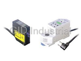
Panasonic ANR11821 Sensor - Laser Head 60-100MM 12-24VDC 20UM
Part Number
ANR11821
Price
Request Quote
Manufacturer
MATSUSHITA
Lead Time
Request Quote
Category
PRODUCTS - A
Specifications
Ambient illuminance (Incandescent lamp)
2,500 lx or less
Beam spot diameter
0.7 x 1.2 mm 0.028 x 0.047 in approx.
Light source
Laser diode (Peak emission wavelength: 650 nm 0.026 mil)
Linearity error (Note 2)
Within ±0.2 % of F.S.
Measuring Range
±20 mm ±0.787 in
Protection (excluding connector)
IP67 (IEC)
Pulse width / Max.output /Laser class
15 µs (Duty 50 %) / 0.4 mW (Peak value) / Class 1 (IEC 60825-1), (Class II for FDA regulations conforming type
Resolution
10Hz-20 µm 0.787 mil 100Hz-65 µm 2.559 mil 1kHz-200 mm 7.874 in
Weight (including cable)
Net weight: 300 g approx.
Features
- High-precision measurements, comparative output (amount of light / displacement) function
- New circuitry lowers costs
- The LM10 makes laser sensors super easy to use!
- The LM10’s cost-performance ratio far outstrips the competition
Datasheet

Extracted Text
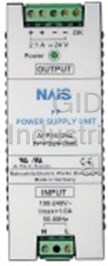
Matsushita Electric Works
LM10
Micro Laser Displacement Sensor
The LM10 makes laser
sensors super easy to use!
Conforming to
EMC Directive
High-precision measurements, comparative output (amount of light / displacement) function New circuitry lowers costs
In addition to conventional analog Measurement principle of LM10 LM10 uses the single-channel IC, which
output, it is equipped with standard (optical triangulation) reduces the dual-channel processing
ON / OFF control output (single / Part of the light rays which come from requirement of conventional products to
double comparator) enabling its use as the target object by means of diffuse a single channel. Building the arithmetic
a photoelectric sensor. It is compatible reflection produce a light spot on the circuits into the IC has made it possible
for ‘micro-spotting’ and ‘high-precision’ position sensing device (PSD). This to reduce costs.
applications normally reserved for light spot varies depending on the
lasers. displacement of the target object. By
Conventional circuit LM10
Signal
measuring the fluctuations in the light
Sensor head Sensor head
processing
spot, LM10 can measure the distance circuit
Setting modes and types of ON / OFF control
of the target object.
Type Standard mode Intensity mode
Position sensing device (PSD)
Window Distance judgment
No mode setting
comparator (3 value output) Beam-receiving lens
a
Controller Controller
Power
Single Distance judgment Intensity judgment
b circuit
comparator (2 value output) (2 value output)
Light receiver
Light emitter
Distance judgment: ON / OFF control on the basis
of distance measurement.
Beam-emitting lens
Intensity judgment: ON / OFF control on the basis
Center point
of received light level.
Emitting element
(semiconductor laser)
Measuring range
AB
918
GP-A GP-X LD LA LA-300 HL-T1 LM10 LH-50 HL-C1
MEASUREMENT SENSORS
Magnetic Displacement Light / Thru-beam Type Light / Reflective Type
LM10
The LM10’s cost-performance ratio far outstrips the competition Globally usable
This micro laser sensor LM10 comply
with the requirements of the relevant
EC Directives (CE marking). Not only
Shape recognition
Measuring
can they work well in devices made for
Position displacement measurement
sensors
Thickness measurement
European industry but also possess
LM10
enhanced electromagnetic environment
High-precision position fixing
performance making them safe to use.
High-precision detection of presence / absence
For the controller’s comparative output,
General purpose
in addition to the NPN transistor output,
photoelectric
Simple position fixing
sensors the PNP transistor output is also
Detection of presence / absence
available.
Price
Use LM10 with confidence. It meets for class 1 laser safety (IEC standards) Interchangeable sensor heads
In addition to our laser Class 2 products, a full line of Class 1 products have been Nine types of sensor heads and four
added. Development of a high-precision aspheric surface plastic lens has made it types of controllers can be freely
possible to maintain both high precision and Class 1 safety. The visible light spot combined in 36 different ways. Unlike
makes it easy to see and safe to use. with conventional sensors, these
heads and controllers are completely
interchangeable to meet any type of
Basic IEC classification outline and requirements (IEC standard 825)
measuring and processing require-
Level of risk Required labeling User precautions
ments, so there is no need for pair
Class 1 Fundamentally safe Explanatory label No precautions necessary management of heads and controllers.
Closing the eyelids will
Class 2 Warning label Avoid the laser beam
protect the eyes.
Excellent in the following circumstances...
Direct observation is Remote interlock Safety manager,
Class 3 (B)
• When carrying out repairs
dangerous. connector Remote safety device
Warning label, Suppose an accident on
Key switch,
High output, Safety goggles, the production line
Class 4 Beam cut-off device,
danger of skin damage Safety clothing, damages the sensor head.
Laser leakage warning
Employee training
With the
MICRO LASER DISPLACEMENT
SENSOR LM10...
...all you have to do is
replace the sensor head.
As long as there is a spare
sensor available, the prob-
lem can be solved without
stopping the production
line.
• When changing to a different model
Suppose that after
purchasing the sensor it
becomes necessary to
switch to a different model
due to changes in the
object you are measuring.
With the
MICRO LASER DISPLACEMENT
SENSOR LM10...
...all you have to do is buy
a new sensor head. The
current controller need not
be replaced.
919
Detection Measurement
Resolution
Magnetic Displacement Light / Thru-beam Type Light / Reflective Type
MEASUREMENT SENSORS
GP-A GP-X LD LA LA-300 HL-T1 LM10 LH-50 HL-C1
LM10
APPLICATIONS
Stage position check Measuring packing-tape thickness Slack detection
Detection of pallet orientation Measuring board thickness Wood surface form detection
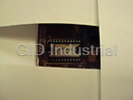
Construction material overlap detection Asymmetry detection Detecting edge of IC
Detecting IC package components IC insertion presence detection Inner-chamber evenness detection
equipment
Aluminum disk
Suction pad
Glass
window
Wafer
Vacuum
chamber
Detecting edge of rubber sheet Inspection of tire groove depth Tire finished product dimension detection
920
GP-A GP-X LD LA LA-300 HL-T1 LM10 LH-50 HL-C1
MEASUREMENT SENSORS
Magnetic Displacement Light / Thru-beam Type Light / Reflective Type
LM10
ORDER GUIDE
Sensor heads
Laser class Type Measuring range Resolution Spot diameter Model No.
LM10-50 50�10 mm 1.969�0.394 in 005 !m 0.197 mil 0.6�1.1 mm 0.024�0.043 in ANR1150
ANR1151
LM10-50S 50�10 mm 1.969�0.394 in 005 !m 0.197 mil 0.09�0.05 mm 0.004�0.002 in
Class 1
LM10-80 80�20 mm 3.150�0.787 in 020 !m 0.787 mil 0.7�1.2 mm 0.023�0.047 in ANR1182
LM10-130 130�50 mm 5.118�1.969 in 100 !m 3.937 mil 0.7�1.4 mm 0.028�0.055 in ANR1115
ANR1250
LM10-50 50�10 mm 1.969�0.394 in 001 !m 0.039 mil 0.6�1.1 mm 0.024�0.043 in
LM10-50S 50�10 mm 1.969�0.394 in 001 !m 0.039 mil 0.09�0.05 mm 0.004�0.002 in ANR1251
Class 2 80�20 mm 3.150�0.787 in 004 !m 0.157 mil 0.7�1.2 mm 0.028�0.047 in ANR1282
LM10-80
LM10-130 130�50 mm 5.118�1.969 in 020 !m 0.787 mil 0.7�1.4 mm 0.028�0.055 in ANR1215
LM10-250 250�150 mm 9.843�5.906 in 150 !m 5.906 mil 0.8�1.5 mm 0.031�0.059 in ANR1226
Controllers
Output Specifications Model No.
Built-in single comparator ANR5131
�5 V
Built-in window comparator ANR5231
Controller
Built-in single comparator ANR5141
4 to 20 mA
(NPN output)
Built-in window comparator ANR5241
Note: NPN and PNP outputs are coordinated as per all the models’ comparative outputs.
Extension cable (for sensor Class 2 types only) for connection to the intermediate cable (1.5 m 4.921 ft intermediate cable is supplied with Class 2 type sensor heads)
Designation Specifications Model No.
02 m 06.562 ft cable length ANR81020
03 m 09.843 ft cable length ANR81030
05 m 16.404 ft cable length ANR81050
Extension cable (Flexible cable) 08 m 26.247 ft cable length ANR81080
10 m 32.808 ft cable length ANR81100
20 m 65.617 ft cable length ANR81200
30 m 98.425 ft cable length ANR81300
SENSOR HEAD AND CONTROLLER ASSEMBLY
Range: 50 �10 mm 1.969�0.394 in
Class 1
(ANR1150)
Resolution: 5 !m 1.969 mil
Range: 50 �10 mm 1.969 �0.394 in Single comparator type
(ANR1151)
Resolution: 5 !m 1.969 mil
(ANR5131)
Range: 80 �20 mm 3.150�0.787 in
(ANR5141)
(ANR1182)
Resolution: 20 !m 0.787 mil
Range: 130 �50 mm 5.118�1.969 in
(ANR1115)
Resolution: 100 !m 3.937 mil
2 m 6.562 ft.
Single comparator judgment output
(displacement / amount of light).
Range: 50 �10 mm 1.969�0.394 in
Class 2
(ANR1250)
Resolution: 1 !m 0.039 mil
Window comparator type
Range: 50 �10 mm 1.969�0.394 in
(ANR1251)
Resolution: 1 !m 0.039 mil
(ANR5231)
Range: 80 �20 mm 3.150�0.787 in (ANR5241)
(ANR1282)
Resolution: 4 !m 0.157 mil
Range: 130 �50 mm 5.118�1.969 in
(ANR1215)
Resolution: 20 !m 0.787 mil
Range: 250 �150 mm 9.843�5.906 in
Resolution: 150 !m 5.906 mil
(ANR1226)
0.5 m 1.640 ft
1.5 m 4.921 ft Window comparator judgment output
(displacement).
With LCD monitor.
Relay connector Intermediate cable
Note: Extension cable is connected to the intermediate cable.
921
MICRO LASER MICRO LASER
SENSOR LM10 SENSOR LM10
LOW HIGH OPRRATION
LASER LASER LASER LASER
LOW HIGH
SET SET DISPLACE SET
MENT
DISPLACEMENT
V
ADJ ADJ
LOW HIGH SET
- + - +
SPEED(Hz) GAIN SPEED(Hz)
GAIN
AUTO LOW AUTO LOW
Magnetic Displacement Light / Thru-beam Type Light / Reflective Type
MEASUREMENT SENSORS
GP-A GP-X LD LA LA-300 HL-T1 LM10 LH-50 HL-C1
LM10
SPECIFICATIONS
Sensor heads
Class 1 type
Model No.
ANR1150 ANR1151 ANR1182 ANR1115
Item
Measurement center distance 50 mm 1.969 in 50 mm 1.969 in 80 mm 3.150 in 130 mm 5.118 in
Measuring range �10 mm �0.394 in �10 mm �0.394 in �20 mm �0.787 in �50 mm �1.969 in
Light source Laser diode (Wavelength: 685 nm 0.027 mil)
Pulse width / Max.output /
15 !s (Duty 50 %) / 0.4 mW (Peak value) / Class 1 (IEC 825)
Laser class
Beam spot diameter
0.6 � 1.1 mm 0.09 � 0.05 mm 0.7 � 1.2 mm 0.7 � 1.4 mm
Representative values from a
0.024 � 0.043 in 0.004 � 0.002 in 0.028 � 0.047 in 0.028 � 0.055 in
(
measurement center distance
10 Hz 5 !m 0.197 mil 5 !m 0.197 mil 20 !m 0.787 mil 100 !m 03.937 mil
Resolution (2σ) 100 Hz 16 !m 0.630 mil 16 !m 0.630 mil 65 !m 2.559 mil 330 !m 12.992 mil
1 kHz 50 !m 1.969 mil 50 !m 1.969 mil 200 !m 7.874 mil 1 mm 00.039 in
Linearity error (Note) Within �0.2 % of F.S.
Protection
IP67 (IEC)
(excluding connector)
Ambient illuminance
2,500 ?x or less
(Fluorescent lamp)
Weight (including cable) 300 g approx.
Note: White ceramics is the target of this value.
Class 2 type
Model No.
ANR1250 ANR1251 ANR1282 ANR1215 ANR1226
Item
Measurement center distance 50 mm 1.969 in 50 mm 1.969 in 80 mm 3.150 in 130 mm 5.118 in 250 mm 9.843 in
Measuring range �10 mm �0.394 in �10 mm �0.394 in �20 mm �0.787 in �50 mm �1.969 in �150 mm �5.906 in
Light source Laser diode (Wavelength: 685 nm 0.027 mil)
Pulse width / Max.output /
15 !s (Duty 50 %) / 1.6 mW (Peak value) / Class 2 (IEC 825)
Laser class
Beam spot diameter
0.6 � 1.1 mm 0.09 � 0.05 mm 0.7 � 1.2 mm 0.7 � 1.4 mm 0.8 � 1.5 mm
Representative values from a
0.024 � 0.043 in 0.004 � 0.002 in 0.028 � 0.047 in 0.028 � 0.055 in 0.031 � 0.059 in
(
measurement center distance
10 Hz 1 !m 0.039 mil 1 !m 0.039 mil 4 !m 0.157 mil 20 !m 0.787 mil 150 !m 05.906 mil
Resolution (2σ) 100 Hz 3.5 !m 0.138 mil 3.5 !m 0.138 mil 13 !m 0.512 mil 65 !m 2.551 mil 500 !m 19.685 mil
1 kHz 10 !m 0.394 mil 10 !m 0.394 mil 40 !m 1.575 mil 200 !m 7.874 mil 1.5 mm 0.059 in
Linearity error (Note) Within �0.2 % of F.S. Within �0.4 % of F.S.
Protection
IP67 (IEC)
(excluding connector)
Ambient illuminance
3,000 ?x or less 2,500 ?x or less
(Fluorescent lamp)
Weight Sensor (including cable): 240 g approx., Intermediate cable: 130 g approx.
Note: White ceramics is the target of this value.
922
GP-A GP-X LD LA LA-300 HL-T1 LM10 LH-50 HL-C1
MEASUREMENT SENSORS
Magnetic Displacement Light / Thru-beam Type Light / Reflective Type
(
(
LM10
SPECIFICATIONS
Controllers
Model No.
ANR5131 ANR5141 ANR5231 ANR5241
Item
Comparative output type Single comparator Window comparator
Analog output �5 V/F.S. (2 mA max.) 4 to 20 mA/F.S. (250 Ω max.) �5 V/F.S. (2 mA max.) 4 to 20 mA/F.S. (250 Ω max.)
Output impedance 50 Ω 50 Ω
Zero-point adjustment Within �10 % of F.S.
Temperature drift
Within �(0.03 % of F.S.) / °C Within �(0.04 % of F.S.) / °C Within �(0.03 % of F.S.) / °C Within �(0.04 % of F.S.) / °C
(Sensor and controller set)
Response frequency (�3 dB) 1 kHz / 100 Hz / 10 Hz
Response time (10 to 90 %) 0.4 ms / 4 ms / 40 ms (Switchable)
NPN open collector 2 Nos. (Note 1) NPN open collector 3 Nos. (Note 1)
Comparative output
(100 mA, 30 V DC or less, residual voltage 1.5 V or less) (100 mA, 30 V DC or less, residual voltage 1.5 V or less)
Hysteresis 0.15 % of F.S. or less
Alarm output NPN open collector 1 No. (100 mA, 30 V DC or less, residual voltage 1.5 V or less)
Intensity monitor output �5 V
Comparative timing Input No voltage input (when earthing, no comparative output allowed)
Sensor head: Measuring range display LED (RANGE)
Displacement display Sensor head: Measuring range display LED (RANGE)
Controller: LCD 3 digit display
Gain selection AUTO / LOW (switchable)
Mutual interference prevention (Note 2) Between 2 sets
�10
Operating voltage range 12 to 24 V DC % including ripple 0.5 V (P-P)
�15
Current consumption
250 mA or less (at 12 V DC), 125 mA or less (at 24 V DC)
(Sensor and controller set)
Weight (including cable) 180 g approx.
Notes: 1) PNP output type is also available.
Notes: 2) The value of the linearity characteristics, resolution and response time might get worse.
Common
Insulation resistance (Initial) Between external DC input and sensor metal parts (except for connector metal parts) 20 MΩ or more (at 500 V DC megger)
Voltage withstandability (Initial) Between external DC input and sensor metal parts (except for connector metal parts) AC 500 V 1 min
Vibration resistance 10 to 55 Hz (1 cycle/min.) double amplitude of 1.5 mm 0.059 in (controller: 0.75 mm 0.030 in),
(Screw installation) in X, Y and Z directions for two hours each
Shock resistance (Screw installation) 20 G or more, in X, Y and Z directions for three times each
Ambient temperature 0 to�50 °C �32 to�122 °F, Storage: �20 to�70 °C �4 to�158 °F
Ambient humidity 35 % to 85 % RH (No dew condensation)
Note: If there is no description for measurement conditions, the test is performed under operating voltage 24 V DC, ambient temperature �20° C �68 °F, gain
AUTO, response frequency 10 Hz, interference prevention OFF and white ceramics as a target at a measurement center distance.
923
Magnetic Displacement Light / Thru-beam Type Light / Reflective Type
MEASUREMENT SENSORS
GP-A GP-X LD LA LA-300 HL-T1 LM10 LH-50 HL-C1
LM10
I/O CIRCUIT AND WIRING DIAGRAMS
Wiring and functions 5
Intensity monitor output [red, shielding (GND)]
Single comparator type • Analog voltage (�5 V to�5 V) is output corresponding to
the amount of light reflected from the target. If the amount
[Brown] 12 to 24 V DC
of light increases, the voltage value becomes larger and if
[Blue] 0 V
[White] Analog displacement output (with shielding) it decreases, the voltage value becomes smaller.
[Shielding] Analog ground
[Red] Intensity monitor output
MICRO LASER (Voltage output type)
SENSOR LM10 [Green] Mutual interference prevention input
OPRRATION
Analog displacement output
LASER LASER [Yellow] Mutual interference prevention output
50 Ω
DISPLACE
SET
MENT
White
[Black] Comparative output (FAR / LIGHT ON)
[Gray] Comparative output (NEAR / DARK ON)
ADJ (Current output type)
SET
[White] Comparative and alarm output COM.
- +
Shield wire
SPEED(Hz) GAIN
[Orange] Alarm output
GND
[Violet] Displacement / intensity comparative selection input
AUTO LOW
[Light blue] Comparative timing input
GND
GND
50 Ω
Red Intensity monitor output
Window comparator type
Laser sensor Analog converter etc.
[Brown] 12 to 24 V DC
[Blue] 0 V
6
Alarm output [orange, white (COM)]
[White] Analog displacement output (with shielding)
• Outputs during insufficient light (DARK) or too much light
[Shielding] Analog ground
[Red] Intensity monitor output
(BRIGHT).
MICRO LASER
SENSOR LM10 [Green] Mutual interference prevention input
LOW HIGH
LASER LASER [Yellow] Mutual interference prevention output
LOW HIGH
SET 7
SET Comparative output
[Black] Comparative output (HIGH)
DISPLACEMENT
Single comparator type [black, gray, white (COM)]
[Gray] Comparative output (IN RANGE)
V
ADJ
LOW HIGH
[Violet] Comparative output (LOW)
- +
Displacement /
SPEED(Hz) GAIN [White] Comparative and alarm output COM.
intensity comparative Comparing operations
[Orange] Alarm output
AUTO LOW
selection input [Violet]
[Light blue] Comparative timing input
When displacement data is set value or over
(far side): FAR / LIGHT ON output is ON.
When not connected
When displacement data is less than set value
(near side): NEAR / DARK ON output is ON.
1 Power input [brown (�) � blue (�)]
When intensity data is set value or over (near
• Input 12 to 24 V DC.
side): FAR / LIGHT ON output is ON.
When connected to 0 V
When intensity data is less than set value (far
[blue]
2 Comparative timing input [light blue]
side): NEAR / DARK ON output is ON.
• While shorted to the 0 V (blue), comparative output is
Note: With the single comparator type, connecting the violet wire and blue
prevented. When using a transistor to establish the timing,
wire changes from the analog displacement output to the light amount
use a transistor with a residual output voltage of 1.5 V or
monitoring value output.
less during output.
Window comparator type [black, gray, violet, white (COM)]
Comparative timing input connection example
Judgment result of analog displacement data is output.
+
LOW [violet] Outputs when below the set value’s lower limit.
Light blue
Outputs when between the set value’s lower and
IN RANGE [gray]
upper limits.
Blue
–
Laser sensor
Photoelectric sensor etc.
HIGH [black] Outputs when above the set value’s upper limit.
3
Mutual interference prevention I/O [green (input),
Description of comparative output operations
yellow (output)]
Frequently asked questions
What makes Elite.Parts unique?

What kind of warranty will the ANR11821 have?
Which carriers does Elite.Parts work with?
Will Elite.Parts sell to me even though I live outside the USA?
I have a preferred payment method. Will Elite.Parts accept it?
Why buy from GID?

Quality
We are industry veterans who take pride in our work

Protection
Avoid the dangers of risky trading in the gray market

Access
Our network of suppliers is ready and at your disposal

Savings
Maintain legacy systems to prevent costly downtime

Speed
Time is of the essence, and we are respectful of yours
Related Products
MATSUSHITA AN630U Driver IC

Matsushita ANR5131 Sensor
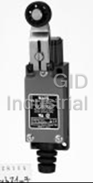
Matsushita AZ-8181 Limit Compact Switch - Vertical W/Remote wire control plunger
Request a Quote

The quote request has been received
Close

Facing challenges or have inquiries? Feel free to contact us!
Call Us +1-469-283-2440
What they say about us
FANTASTIC RESOURCE
One of our top priorities is maintaining our business with precision, and we are constantly looking for affiliates that can help us achieve our goal. With the aid of GID Industrial, our obsolete product management has never been more efficient. They have been a great resource to our company, and have quickly become a go-to supplier on our list!
Bucher Emhart Glass
EXCELLENT SERVICE
With our strict fundamentals and high expectations, we were surprised when we came across GID Industrial and their competitive pricing. When we approached them with our issue, they were incredibly confident in being able to provide us with a seamless solution at the best price for us. GID Industrial quickly understood our needs and provided us with excellent service, as well as fully tested product to ensure what we received would be the right fit for our company.
Fuji
HARD TO FIND A BETTER PROVIDER
Our company provides services to aid in the manufacture of technological products, such as semiconductors and flat panel displays, and often searching for distributors of obsolete product we require can waste time and money. Finding GID Industrial proved to be a great asset to our company, with cost effective solutions and superior knowledge on all of their materials, it’d be hard to find a better provider of obsolete or hard to find products.
Applied Materials
CONSISTENTLY DELIVERS QUALITY SOLUTIONS
Over the years, the equipment used in our company becomes discontinued, but they’re still of great use to us and our customers. Once these products are no longer available through the manufacturer, finding a reliable, quick supplier is a necessity, and luckily for us, GID Industrial has provided the most trustworthy, quality solutions to our obsolete component needs.
Nidec Vamco
TERRIFIC RESOURCE
This company has been a terrific help to us (I work for Trican Well Service) in sourcing the Micron Ram Memory we needed for our Siemens computers. Great service! And great pricing! I know when the product is shipping and when it will arrive, all the way through the ordering process.
Trican Well Service
GO TO SOURCE
When I can't find an obsolete part, I first call GID and they'll come up with my parts every time. Great customer service and follow up as well. Scott emails me from time to time to touch base and see if we're having trouble finding something.....which is often with our 25 yr old equipment.
ConAgra Foods