

 Manufacturers
LENZE AC TECH EVF8216E

Description
Lenze's EVF8216-E Inverter, is a frequency inverter for single-phase and three
phase mains connection, line-side, and motor-side accessories. Accessories for
braking, accessories for networking with host system, and device variants for
special applications. User-friendliness, an attachable operating module with
an LCD display makes it easy to set parameters for and configure your drive
system. The operating module also displays the status of the drive and is
used for troubleshooting as well.
Part Number
EVF8216E
Price
Request Quote
Manufacturer
LENZE AC TECH
Lead Time
Request Quote
Category
PRODUCTS - E
Datasheet

Extracted Text
490 826 Lenze Global Drive Frequency inverters 8200/9300 vector 0.37 … 90 kW Lenze Drive Systems GmbH, Postfach 1013 52, D-31763 Hameln Site: Hans-Lenze-Straße 1, D-31855 Aerzen, Tel. ++49 (0) 5154 82-0, Fax ++49 (0) 5154 82-21 11 CTi Automation - Phone: 800.894.0412 - Fax: 208.368.0415 - Web: www.ctiautomation.net - e.mail: info@ctiautomation.net E-mail: Lenze@Lenze.de · Internet: http://www.Lenze.com Subject to technical modifications · Printed in Germany 05/04 by ME / LHM · 02/12 en Product selection and orders This catalog will help you to select and order the AC drive you need quickly and easily. It features: • Static frequency inverters for controlling three-phase AC motors • Accessories for assembling and connecting the inverters • Application examples • Order forms CTi Automation - Phone: 800.894.0412 - Fax: 208.368.0415 - Web: www.ctiautomation.net - e.mail: info@ctiautomation.net 2 Lenze Frequency inverter product information Overview Mains Mains fuses or EFS... range automatic circuit breakers Mains chokes type ELN... Mains Interference filter filter EZF... EZN... EMZ8201BB Special mounting kits EJ... operator terminal Automation module e.g. EMF2xxxIB Frequency inverter e.g. EVF82xx-E Brake resistor ERB... Brake chopper e.g. EMB825.-E Motor filter Sinusoidal filter ELM... EZS... M 3~ 3 Lenze CTi Automation - Phone: 800.894.0412 - Fax: 208.368.0415 - Web: www.ctiautomation.net - e.mail: info@ctiautomation.net An introduction to Lenze Intelligent drives in automation Application intelligence is the feature which sets the Global The freely connectable internal control structure of the Drive controller apart. When used in machines, it offers servo inverters, servo register control, servo cam and 9300 designers enormous potential for reducing costs. servo position controller eliminates the need for numerous external I/O devices. For example, complete position Starting with the Global Drive 8200 frequency inverters for control has been integrated into the 9300 servo position use in standard applications or HVAC and pump drives, controller via the software. Each device type provides frequently used additional automation features (e.g. PID technology functions which are able, for example, to controller) have been integrated into the device. execute subprocesses. The additional switching elements in the system can be evaluated via the control inputs and outputs or via the system bus. There’s only one name for intelligent drives: Global Drive. CTi Automation - Phone: 800.894.0412 - Fax: 208.368.0415 - Web: www.ctiautomation.net - e.mail: info@ctiautomation.net List of abbreviations Abbreviations used in this catalog Drive controllers General U [V] Mains voltage 82xxE Types 8201 to 8204E and mains I [A] Mains current types 8211 to 8227E mains U [V] DC bus voltage 820xE Types 8201 to 8204E DC I [A] Rated current/Output current 821xE Types 8211 to 8218E (standard + Klima) r I [A] Maximum output current 824xE Types 8241 to 8246E (standard + Klima) max 822xE Types 8221 to 8227E (standard + Klima) P [kW] Rated motor power 825xE Types 8251 to 8253E r S [kVA] Inverter output power 93xxEV Types 9321EV to 9333EV r P [W] Inverter power loss loss AC Alternating current/voltage f [kHz] Chopper frequency DC Direct current/voltage ch f [Hz] Set maximum frequency max f [Hz] Field frequency DIN Deutsches Institut für Normung d L [mH] Inductance EMC Electromagnetic compatibility R [Ω] Resistance EN European standard IEC International Electrotechnical Commission IP International Protection Code NEMA National Electrical Manufacturers Association VDE Verband deutscher Elektrotechniker CE Communauté Européene IM International Mounting Code CTi Automation - Phone: 800.894.0412 - Fax: 208.368.0415 - Web: www.ctiautomation.net - e.mail: info@ctiautomation.net 6 Lenze Contents DC fuses _______________________________________ 91 DC fuses for DC-bus operation and Product information DC power supply________________________________91 Product information 8200___________________________ 8t Product information - 9300 vector __________________ 10 8201BB operating module _________________________ 94 Design - 8200 and 9300 vector _____________________ 13 9371BC operating module _________________________ 95 Frequency inverters ________________________________________________________9 Plug-in modules for 8200 inverters _________________ 96 System bus components for 9300 vector ___________ 98 Ordering data Selecting a drive system __________________________ 14 Additional accessories ___________________________ 100 Setpoint potentiometer_________________________ 100 Digital display _________________________________ 101 Design - 82xx Communication with a host system________________ 102 Overview of the 8200 frequency inverter_____________ 16 Overview of the 8200 klima frequency inverter _____ 17 Overview of accessories for the 8200 inverter_______ 104 Accessories for General data _____________________________________ 18 8201 - 8204 frequency inverters_________________ 105 8200 range ratings______________________________ 19 Accessories for 8210 range ratings______________________________ 20 8211 - 8218 frequency inverters_________________ 106 8240 range ratings______________________________ 24 Accessories for 8220 range ratings______________________________ 28 8241 - 8246 frequency inverters_________________ 108 Accessories for Design - 8200 and 9300 vector 8221 - 8227 frequency inverters_________________ 110 Overview of the 9300 vector _____________________32 Accessories for General data____________________________________33 supply and regenerative feedback modules _______111 Ratings ________________________________________34 Overview of accessories for the 9300 vector _______ 112 Mechanical installation ____________________________ 43 Accessories for General information _____________________________ 43 9321 - 9333 frequency inverters_________________ 114 Assembly with fixing rails ________________________ 44 Mounting on DIN rails ___________________________ 47 Assembly with thermal separation ________________ 48 Application examples Flat horizontal assembly _________________________ 50 Mounting on a swivel bracket ____________________ 50 Connecting diagrams _____________________________ 118 8200 range power connection___________________ 118 Line-side electrical installation _____________________ 51 8210/8240/8220 range power connection ________ 119 Line protection _________________________________ 51 Connection of control terminals CE-typical installation ___________________________ 56 for the 8200 and 8210 ranges ___________________ 120 Mains chokes __________________________________ 58 Connection of control terminals for the 8240/8220 Interference suppression to EN 55011 limiting value __ ranges _______________________________________ 121 class A _______________________________________ 62 9300 vector range power connection ____________ 123 Interference suppression to EN 55011 limiting value __ Connecting diagrams for 9300 vector class B _______________________________________ 62 frequency inverters ____________________________ 124 Mains filter A for 8200 and 9300 vector ___________ 66 Mains filter B for 8200 and 9300 vector ___________ 70 Applications ____________________________________ 125 Subassembly mains filters limiting value class A and B DC-bus operation _____________________________ 125 (15 kW … 90 kW) ________________________________73 Pump application______________________________ 127 Air conditioning system ________________________ 128 Motor-side electrical installation ____________________ 75 Level control __________________________________ 129 Output filters ___________________________________ 75 Step control __________________________________ 130 Motor filters____________________________________ 76 Traversing control _____________________________ 131 Sinusoidal filters ________________________________ 78 Pilot frequency - Slave _________________________ 132 Dancer positioning control______________________ 133 Braking__________________________________________ 80 Options________________________________________ 80 Brake modules _________________________________ 81 Order forms Brake choppers ________________________________ 84 ________________________________________________ 136 Brake resistors _________________________________ 86 Supply and regenerative feedback modules _________ 88 Lenze worldwide General data ___________________________________ 88 ________________________________________________ 144 Mains filter A __________________________________ 90 CTi Automation - Phone: 800.894.0412 - Fax: 208.368.0415 - Web: www.ctiautomation.net - e.mail: info@ctiautomation.net 7 Lenze i Product information 8200 A complete programme CE conformity – Frequency inverters for single-phase and three- The 8200 range frequency inverters meet the phase mains connection requirements of the following EU guidelines: – Line-side and motor-side accessories – CE conformance according to the Low-Voltage – Accessories for braking Directive – Accessories for networking with host system – CE conformance with the EU’s EMC directive for – Device variants for special applications generic drive configurations with frequency inverters User-friendliness An attachable operating module with an LCD Overload capacity display makes it easy to set parameters for and Flux Torque Control (FTC) can make available up to configure your drive system. The operating module 180% rated torque. This significantly increases the also displays the status of the drive and is used for drive’s torque and dynamics. troubleshooting as well as for transferring parameters to other devices. Operational reliability An adjustable slip compensation function compensates load-dependent speed deviations Ready for immediate operation without complex speed feedback. The maximum The frequency inverters are preset for standard current limitation ensures stable operation at all operation, e.g. with Lenze geared motors. times with static and dynamic loads. The preset parameters include: –Maximum torque at low frequencies Adaptability – Safe start with maximum load The selectable form of the V/f characteristic enables – Controlled acceleration and deceleration due to the frequency inverter to be adapted to loads with current limiting control constant or square-law torque. The integrated flying – Assignment of standard functions to inputs restart circuit enables the machine to be restarted and outputs even if the shaft is still rotating. Communication options Optimised performance The frequency inverters communicate with a higher- The performance of the devices can be optimised by level host system via attachable communication applying 150% or 120% overload: modules: – 150% overload for example for transportation systems, packaging machines, etc. – LECOM-AB: Networking via the RS232/485 – 120% overload for example for pumps, interface air conditioning systems, etc. – LECOM-LI: Networking via optical fibres – INTERBUS-S: Remote bus link with DRIVECOM profile 21 – System bus Link to I/O terminals, (CAN): as well as links between a number of inverters –PROFIBUS: Serial coupling to PROFIBUS-DP HVAC version The following features are amongst those required in HVAC and pump drive applications: – PID controller – Manual-remote changeover – Belt monitoring The 8200 HVAC and pump drive inverter meets these requirements. CTi Automation - Phone: 800.894.0412 - Fax: 208.368.0415 - Web: www.ctiautomation.net - e.mail: info@ctiautomation.net 8 Lenze i Product information 8200 Versatility Ease of controller connection Many different types of three-phase AC motors can The plug-in terminal system means that all be controlled: control connections can be accessed easily from – Three-phase asynchronous motors outside the unit. – Three-phase reluctance motors – Motors for use in hazardous areas A Lenze geared motor – Your ideal partner (pressure-enclosed) In terms of technology, Lenze geared motors are – Medium-frequency motors up to max. 480 Hz perfectly compatible with 8200 frequency inverters. Commissioning could not be easier, as the frequency The correct setpoint source for every application: inverter is configured for the motor data. There is no – Via setpoint potentiometer on the control need to set motor data parameters. terminals (You can find more information about Lenze geared – Via master reference voltage or master reference motors in the corresponding catalog.) current on the control terminals – Via the operating module on the frequency Special applications? No problem. inverter Device variants mean that the ranges can be – Via a networking module directly from a adapted for use in any application: host system – Convection-cooled version 4.0 kW upwards Energy-saving Please contact us should you require more The power is adapted to the drive requirements, i.e. information. the momentary torque and current requirements. Space in the control cabinet The frequency inverters are particularly compact as they can be mounted directly side by side, without the need for any clearance in between. Thanks to an extensive range of fixing accessories, they can be used in a variety of mounting positions. CTi Automation - Phone: 800.894.0412 - Fax: 208.368.0415 - Web: www.ctiautomation.net - e.mail: info@ctiautomation.net 9 Lenze i Product information - 9300 vector CE conformity A complete programme 9300 range frequency inverters meet the – Frequency inverter for three-phase mains requirements of the following EU guidelines: connection – CE conformance with the Low-Voltage Directive – Line-side and motor-side accessories – CE conformance with the EU’s EMC directive for – Accessories for braking generic drive configurations with frequency – Accessories for networking with host systems inverters – Device variants for special applications Overload capacity User-friendliness Vector Control can make available up to twice the An attachable operating module with an LCD rated torque. display makes it easy to set parameters for and This significantly increases the drive’s torque and configure your drive system. The operating module dynamics. also displays the status of the drive and is used for troubleshooting as well as for transferring parameters Operational reliability to other devices. Configurable slip compensation can be employed to compensate load-dependent fluctuations in speed Ready for immediate operation without having to apply complex speed feedback. The frequency inverters are preset for standard The maximum current limiting function ensures operation, e.g. with Lenze geared motors. stable operation at every operating point for both The preset parameters include: static and dynamic loads. –V/f characteristic control with adjusted slip compensation Adaptability – Controlled acceleration and deceleration due to The selectable form of the V/f characteristic enables preset current limiting control the frequency inverter to be adapted to loads with – Assignment of standard functions to inputs and constant or square-law torque. The integrated flying outputs restart circuit enables the machine to be restarted even if the shaft is still rotating. Communication options The frequency inverters communicate with a Optimised performance higher-level host system via attachable The performance of the devices can be optimised by communication modules: applying 150% or 120% overload: – 150% overload for example for transportation – LECOM-AB: Networking via the RS232/485 systems, packaging machines, etc. interface – 120% overload for example for pumps, – LECOM-LI: Networking via optical fibres air conditioning systems, etc. – INTERBUS-S: Remote bus link with DRIVECOM profile 21 – System bus Link to I/O terminals, (CAN): as well as links between a number of inverters (integrated) –PROFIBUS: Serial coupling to PROFIBUS-DP CTi Automation - Phone: 800.894.0412 - Fax: 208.368.0415 - Web: www.ctiautomation.net - e.mail: info@ctiautomation.net 10 Lenze i Product information - 9300 vector Versatility Increased functionality makes control significantly easier: Many different types of three-phase AC motors can – Pilot frequency for synchronous operation using be controlled: – Three-phase asynchronous motors simple connectors – Vector Control for maximum dynamics and high – Three-phase synchronous motors starting torque – Three-phase reluctance motors – Motors for use in hazardous areas – Modular, freely configurable control/function blocks which can be linked incredibly easily (pressure-enclosed) – Medium-frequency motors up to max. 600 Hz – Process controller and arithmetic blocks for closed-loop and open-loop control tasks – Integrated system bus for linking a number of The correct setpoint source for every application: – Via setpoint potentiometer on the control controllers current on the control terminals Regenerative feedback modules – Via master reference voltage or master reference current on the control terminals For energy-saving interconnected and multi-axis applications. – Via the operating module on the frequency inverter Ease of controller connection – Via a networking module directly from a The plug-in terminal system means that all control host system current terminals can be accessed easily from outside the unit. Energy-saving The power is adapted to the drive requirements, i.e. the momentary torque and current requirements. A Lenze geared motor – Your ideal partner In terms of technology, Lenze geared motors are Space in the control cabinet perfectly compatible with 93xx frequency inverters. The frequency inverters are particularly compact Commissioning could not be easier, as the frequency inverter is configured for the motor data. There is no as they can be mounted directly side by side, without the need for any clearance in between. need to set motor data parameters. (You can find more information about Lenze Thanks to an extensive range of fixing accessories, geared motors in the corresponding catalog.) they can be used in a variety of mounting positions. Please contact us should you require more information. CTi Automation - Phone: 800.894.0412 - Fax: 208.368.0415 - Web: www.ctiautomation.net - e.mail: info@ctiautomation.net 11 Lenze Your application ... Extruder technology Dosing machines Winding technology ... solved with 8200/9300 vector frequency inverters CTi Automation - Phone: 800.894.0412 - Fax: 208.368.0415 - Web: www.ctiautomation.net - e.mail: info@ctiautomation.net 12 Lenze i Design - 8200 and 9300 vector Inverters for your application Your application Transport and Flow Miniature handling Extruders, conveyor drives drives, equipment, dosing machines, pumps, beverage and wood processing, air conditioning systems snack warehousing, dispensers etc. Task/ Few Industrial Small-scale Complex Application technology applications applications functions Single-phase 8201-8204 8201-8204 with – 0.37 – 2.2 kW Plug-in modules 0.37 – 2.2 kW Three-phase 8211-8218 8211-8218 V020 8211-8218 9321-9333 8221-8227 8221-8227 V020 with Vector 8241-8246 8241-8246 V020 plug-in modules 0.37 – 110 kW 0.37 – 110 kW 0.37 – 110 kW 0.37 – 11 kW Compact design �� � � Short circuit protected �� � � FTC process �� � Vector Control � Flying restart circuit �� � � Bipolar setpoint �� Motor potentiometer �� � � Freely assignable � � �� inputs/outputs Elapsed time � � � meter Fault indication output �� � � DC � � �� braking Slip � � �� compensation Skip frequencies �� PID controller �� Manual/remote � Belt monitoring � 4 parameter sets � Mains � monitoring Pilot frequency input � Sensorless � rotational speed control Modular � function blocks Integrated system bus � CTi Automation - Phone: 800.894.0412 - Fax: 208.368.0415 - Web: www.ctiautomation.net - e.mail: info@ctiautomation.net 13 Lenze � � �� � Design - 8200 and 9300 vector Selecting a drive system Sequence diagram Calculate the inverter power P � 2.2 kW P � 2.2 kW � � Select single-phase or 3-ph. inverter Select 3-ph. inverter � � No Wall mounting? Yes � � supplied Select alternative mounting � � Line protection Fuse Circuit breaker � No Reduce the mains current? Yes � � Select mains choke or mains filter � No RFI filter? Class A Class B � � � Select RFI filter and Select RFI filter or mains choke or mains filter mains filter � � Motor cable < 50 m shielded or 50 to 100 m shielded or 100 m to 200 m shielded Longer motor cable < 100 m unshielded 100 to 200 m unshielded 200 m to 400 m unshielded Select motor filter Select sinusoidal filter Contact Lenze � No Braking on short ramps or with high mass moment of inertia Yes � � Select brake chopper and brake resistor or supply/ regenerative feedback module � Determine the type of operation/control Control via terminals Control via terminals Control and parameter setting Parameter setting via operating module Parameter setting via wiring system via host system ��� Select potentiometer and Select potentiometer and Select fieldbus module operating module fieldbus module � � � Enter data into order form CTi Automation - Phone: 800.894.0412 - Fax: 208.368.0415 - Web: www.ctiautomation.net - e.mail: info@ctiautomation.net 14 Lenze � � � i Ordering data - 8200 and 9300 vector A step-by-step guide to ordering your drive The following sections of this catalog will assist you in finding a tailor-made frequency inverter for your machines. Enter your selection in the order form. Å This section provides extensive information Example: 1. Select the 82XX-E device type • Inverter drive for 7.5 kW motor with 150% (Å Design, Technical data) overload capacity Select the drive controller to control the speed of the three-phase AC motor. The type of device will EVF8217-E depend on the motor power required. 2. Select how the device is to be installed • As the heat sink is installed separately, a smaller (Å Design, Mechanical installation) controlcabinet can be used. Select the accessories for installing your frequency inverter. Frame for thermal separation EJ0004 3. Select the line-side accessories • Drive location: (Å Design, Line-side electrical installation) On an industrial network Select the appropriate fuses and the accessories to ensure conformance with the limiting value classes • Radio interference suppression: specified if the applicable European legislation. The environmental conditions require limiting value class A to EN 55011 RFI filter EZF3-025A001 4. Select the motor-side accessories •Motor cable: (Å Design, Motor-side electrical installation) Length 210 m, unshielded Special measures may be required for motor cables longer than 50m: Select your simple and cost-effective solution with compact motor filters or sinusoidal filters. Sinusoidal filter EZS3-025A 5. Select additional accessories for • For analog setpoint selection via master controlling the device voltage or master current: (Å Design, Additional accessories) Select useful accessories for controlling Setpoint potentiometer ERPD0001k0001W the device: Scale for potentiometer ERZ0001 - Operating module Rotary button for potentiometer ERZ0002 - Automation accessories - Setpoint potentiometer. • If you need a quick and easy device for changing the factory settings: Operating module EMZ8201BB Our example is based on the 82xx-E frequency inverter. Follow the same procedure for the 9300 vector frequency inverter. CTi Automation - Phone: 800.894.0412 - Fax: 208.368.0415 - Web: www.ctiautomation.net - e.mail: info@ctiautomation.net 15 Lenze Design - 8200 Overview of the 8200 frequency inverter Compact frequency inverter for single-phase and three-phase mains connection: • Single-phase:8200 range 0.37 kW -2.2 kW • Three-phase: 8210 range 0.75 kW -11.0 kW 8220 range 15.0 kW - 110.0 kW 8240 range 0.37 kW -11.0 kW Product features 8201-4 8211-18 8221-27 8241-46 Single-phase Three-phase Three-phase Three-phase 0.37 -2.2 kW 0.75 -11.0 kW 15.0-110.0 kW 0.37-11.0 kW Compact design �� � � Load capacity for 1 min. up to 150% I �� � � r Inverter outputs protected against short-circuits �� � � Earth fault check on mains disconnection �� � � Fixed chopper frequency 9.2 kHz � Variable chopper frequency 4, 8, 12 or 16 kHz �� � V/f characteristic control with constant V boost or min � auto boost Motor current control or V/f characteristic control selectable �� � (FTC technique) Mains voltage compensation �� � � Slip compensation �� � � Adjustable current limitation with V/f control �� � � Pulse width modulation inverter with IGBT power stages �� � � Connection for DC bus and brake units �� � � Potential-free analog input and output �� � � Relay outputs (changeover contacts) 1 1 2 2 Isolated (potential-free) digital inputs with programmable functions 4 4 4 4 Up to 3 fixed frequencies (JOG) per parameter set �� � � DC braking �� � � TRIP set and TRIP reset functions �� � � Motor potentiometer �� � � Output frequency up to 240 Hz/480 Hz � Output frequency up to 480 Hz �� � Flying restart with coasting motor �� � � 2 parameter sets �� � � Elapsed time and running time counter �� � � Assembly with thermal separation of power stage, 4.0 kW upwards �� � Attachable accessories 8201BB operating module for control and parameter setting ���� with memory for parameter transfer Serial RS232/485 module, wire or optical fibre 2102IB ���� INTERBUS-S module 2111IB ���� PROFIBUS module 2131IB ���� System bus module 2171IB/2172IB ���� 8274-78IB plug-in modules for function extension ���� CTi Automation - Phone: 800.894.0412 - Fax: 208.368.0415 - Web: www.ctiautomation.net - e.mail: info@ctiautomation.net 16 Lenze Design - 8200 Overview of the 8200 frequency inverter 8200 klima range frequency inverters All standard device features plus the following features for environment technology, HVAC and pump drives 8211-18E-V020 8221-27E-V020 8241-46E-V020 Three-phase Three-phase Three-phase 0.75 -11 kW 15 -110 kW 0.37 -11.0 kW Integrated PID process controller �� � Elimination of mechanical resonances �� � Load loss (V-belt) monitoring �� � Smooth start/stop along S ramps �� � Manual/automatic changeover �� � Motor phase failure detection �� Mains failure detection �� � Inverse setpoint handling �� � Volume flow control without feedback �� � Speed control with feedback �� � Torque control �� � Max. possibilities for analog input signals 2 2 2 Max. possibilities for digital output signals 2 3 3 Level inversion of digital input signals �� � Priority: bus control/terminal control �� � Attachable accessories Analog input module 8279 �� � 8201BB operating module for control and parameter setting �� � with memory for parameter transfer Serial RS232/485 module, wire �� � or optical fibre 2102IB INTERBUS-S module 2111IB �� � PROFIBUS module 2131IB �� � System bus module 2171IB/2172IB �� � 8274-78IB plug-in modules for function extension �� � See page 32 for details of 9300 vector frequency inverters. CTi Automation - Phone: 800.894.0412 - Fax: 208.368.0415 - Web: www.ctiautomation.net - e.mail: info@ctiautomation.net 17 Lenze Design - 8200 General data Range Values Vibration resistance Germanischer Lloyd, general conditions Humidity Humidity class F, no condensation (average relative humidity 85%) Permissible temperature ranges During device transport: - 25°C ... +7 0°C During device storage: - 25°C ... +55°C During device operation: 0°C ... +40°C + 40°C ... +50°C with power derating 2.5% per K Permissible installation height h Up to 1000 m above sea level Without power derating 1000 m above sea level ... 4000 m above sea level 5%/1000m Pollution degree VDE 0110 Part 2 pollution degree 2 Noise emission Requirements to EN 50081-1, EN 50081-2, IEC 22G-WG4 (Cv) 21 Limiting value class A to EN 55011 (industrial area) with mains filter Limiting value class B to EN 55022 (residential area) with mains filter and control cabinet installation Noise immunity Complies with limit values with mains filter Requirements to EN 50082-2, IEC 22G-WG4 (Cv) 21 Requirements Standard Intensity of tests ESD EN61000-4-2 3, i.e. 8 kV with air discharge and 6 kV with contact discharge HF field (housing) EN61000-4-3 3, i.e. 10 V/m; 27 up to 1000 MHz Burst EN61000-4-4 3/4, i.e. 2 kV/5 kHz Surge (on mains cable) IEC 1000-4-5 3, i.e. 1.2/50 µs 1 kV phase-phase, 2 kV phase-PE Insulation strength Overvoltage category III to VDE 0110 Packaging To DIN 4180 - 8201 to 8218: Dust packaging - 8221 to 8227: Shipping container Degree of protection IP20 NEMA 1: Protection against contact Approvals CE: Low-Voltage Directive 8201 - 8218: VDE approval 8241 - 8246, 8221 - 8227: UL 508: Industrial control equipment UL 508C: Power conversion equipment CTi Automation - Phone: 800.894.0412 - Fax: 208.368.0415 - Web: www.ctiautomation.net - e.mail: info@ctiautomation.net 18 Lenze � � Design - 8200 Ratings Frequency inverter for single-phase mains connection Type 8201 8202 8203 8204 Order ref. EVF8201-E EVF8202-E EVF8203-E EVF8204-E Order ref. EVF8202-E compact device -V002 Mains voltage U [V] 1 / N / PE / AC / 230V / 50 Hz / 60 Hz M permissible range 190...260 V ± 0% / 45...65 Hz ± 0% Alternative DC supply U [V] 270 V...360 V ± 0% DC 1) Output voltage 3 / PE / AC / 0...U / 0...50 Hz , up to 240 Hz as an option mains Data for operation on mains: 1 AC / 230 V / 50 Hz / 60 Hz Motor power 4-pole ASM kW 0.37 0.75 1.50 2.20 Output current A 2.6 4.0 7.0 9.5 Max. output current 60 s A 3.9 6.0 10.5 14.2 Output power kVA 1.0 1.5 2.7 3.6 2) Mains r.m.s. current Without mains choke/filter A 5.0 9.0 15.0 – With mains choke/filter 4.2 7.5 12.5 17.0 Power loss W 30 50 70 100 Chopper frequency Up to 9.2 kHz Field frequency Resolution 50 mHz absolute Accuracy Digital setpoint preselection ± 0.05 Hz Analog setpoint preselection - Linearity ± 0.5% max. selected - Temperature sensitivity 0...40°C + 0.4% signal level - Offset ± 0.3% 5 V or 10 V Dimensions a mm64648383 b 180 180 250 250 e 158 198 (158) 211 211 Weight kg 1.0 1.3 2.2 2.2 Weight (compact device) 1.0 1) With mains choke/filter: Max. output voltage = approx. 96% of mains voltage 2) Take the N-conductor load into account if the mains power is being distributed symmetrically on a number of inverters! � b � e a CTi Automation - Phone: 800.894.0412 - Fax: 208.368.0415 - Web: www.ctiautomation.net - e.mail: info@ctiautomation.net 19 Lenze � � � � Design - 8200 Ratings Frequency inverter for three-phase mains connection at 150% overload Type 8211E 8212E 8213E 8214E Order ref. EVF8211-E EVF8212-E EVF8213-E EVF8214-E Order ref. 8200 HVAC and pump drive EVF8211-E EVF8212-E EVF8213-E EVF8214-E -V020 -V020 -V020 -V020 Mains voltage U [V] 3 / N / PE / AC / 460 V / 50 Hz / 60 Hz M permissible range 320...510 V ± 0% / 45...65 Hz ± 0% Alternative DC supply U [V] 450 V...715 V ± 0 % DC 1) Output voltage 3 / PE / AC / 0...U / 0...50 Hz , up to 480 Hz as an option mains Data for operation on 3 AC / 400 V / 50 Hz / 60 Hz mains Motor power 4-pole ASM kW 0.75 1.5 2.2 3.0 Output current A 2.4 3.9 5.5 7.3 Max. output current 60 s A 3.6 5.9 8.3 11.0 Output power kVA 1.6 2.7 3.8 5.2 Data for operation on 3 AC / 460 V / 50 Hz / 60 Hz mains Motor power 4-pole ASM kW 1.1 1.5 2.2 3.7 Output current A 2.4 3.9 5.5 7.3 Max. output current 60 s A 3.6 5.9 8.3 11.0 Output power kVA 1.9 3.1 4.3 5.8 1) Mains r.m.s. current Without mains choke/filter A 3.75 5.85 7.5 - With mains choke/filter 2.5 3.9 5.0 7.0 Power loss W 55 75 90 100 Chopper frequency Adjustable 4 kHz, 8 kHz, 16 kHz Field frequency Resolution 20 mHz absolute Accuracy Digital setpoint preselection ± 0.05 Hz Analog setpoint preselection - Linearity ± 0.5% Reference fmax - Temperature sensitivity 0...40°C + 0.4 % - Offset ± 0 % Dimensions a mm83838383 b 250 250 250 250 e 211 211 211 211 Weight kg 2.2 2.2 2.2 2.2 1) Data for operation with factory setting of 8 kHz chopper frequency � b � e a CTi Automation - Phone: 800.894.0412 - Fax: 208.368.0415 - Web: www.ctiautomation.net - e.mail: info@ctiautomation.net 20 Lenze � � � � Design - 8200 Ratings Frequency inverter for three-phase mains connection at 120% overload Type 8211E 8212E 8213E 8214E Order ref. EVF8211-E EVF8212-E EVF8213-E EVF8214-E Order ref. 8200 HVAC and pump drive EVF8211-E EVF8212-E EVF8213-E EVF8214-E -V020 -V020 -V020 -V020 Mains voltage U [V] 3 / N / PE / AC / 400 V / 50 Hz / 60 Hz M permissible range 320...440 V ± 0% / 45...65 Hz ± 0% Alternative DC supply U [V] 460 V...620 V ± 0 % DC 1) Output voltage 3 / PE / AC / 0...U / 0...50 Hz , up to 480 Hz as an option mains Data for operation on 3 AC / 400 V / 50 Hz / 60 Hz mains Motor power 4-pole ASM kW 1.1 1.5 3.0 3.0 Output current A 3.0 3.9 7.3 7.3 Max. output current 60 s A 3.6 5.9 11.0 11.0 Output power kVA 2.1 2.7 5.2 5.2 1) Mains r.m.s. current Without mains choke/filter A 3.75 5.85 7.5 - With mains choke/filter 2.5 3.9 5.0 7.0 Power loss W 55 75 90 100 Chopper frequency Adjustable 4 kHz, 8 kHz, 16 kHz Field frequency Resolution 20 mHz absolute Accuracy Digital setpoint preselection ± 0.05 Hz Analog setpoint preselection - Linearity ± 0.5% Reference fmax - Temperature sensitivity 0...40°C + 0.4% - Offset ± 0% Dimensions a mm83838383 b 250 250 250 250 e 211 211 211 211 Weight kg 2.2 2.2 2.2 2.2 1) Data for operation with factory setting of 8 kHz chopper frequency � b � e a CTi Automation - Phone: 800.894.0412 - Fax: 208.368.0415 - Web: www.ctiautomation.net - e.mail: info@ctiautomation.net 21 Lenze � � � � Design - 8200 Ratings Frequency inverter for three-phase mains connection at 150% overload Type 8215E 8216E 8217E 8218E Order ref. EVF8215-E EVF8216-E EVF8217-E EVF8218-E Order ref. 8200 HVAC and pump drive EVF8215-E EVF8216-E EVF8217-E EVF8218-E -V020 -V020 -V020 -V020 Mains voltage U [V] 3 / N / PE / AC / 460 V / 50 Hz / 60 Hz M permissible range 320...510 V ± 0% / 45...65 Hz ± 0% Alternative DC supply U [V] 450 V...715 V ± 0 % DC 1) Output voltage 3 / PE / AC / 0...U / 0...50 Hz , up to 480 Hz as an option mains Data for operation on 3 AC / 400 V / 50 Hz / 60 Hz mains Motor power 4-pole ASM kW 4.0 5.5 7.5 11.0 Output current A 9.4 13.0 16.5 23.5 Max. output current 60 s A 14.1 19.5 24.8 35.3 Output power kVA 6.5 9.0 11.4 16.3 Data for operation on 3 AC / 460 V / 50 Hz / 60 Hz mains Motor power 4-pole ASM kW 5.5 7.5 11.0 15.0 Output current A 9.4 13.0 16.5 23.5 Max. output current 60 s A 14.1 19.5 24.8 35.3 Output power kVA 7.5 10.3 13.1 18.7 1) Mains r.m.s. current Without mains choke/filter A 13.2 18.0 22.5 - With mains choke/filter 8.8 12.0 15.0 20.5 Power loss W 150 200 280 400 Chopper frequency Adjustable 4 kHz, 8 kHz, 16 kHz Field frequency Resolution 20 mHz absolute Accuracy Digital setpoint preselection ± 0.05 Hz Analog setpoint preselection - Linearity ± 0.5% (reference fmax) - Temperature sensitivity 0...40°C + 0.4 % - Offset ± 0 % Dimensions a mm125125125125 b 250 250 250 250 e 218 218 218 218 Weight kg 5.3 5.3 5.3 5.3 1) Data for operation with factory setting of 8 kHz chopper frequency � b � e a CTi Automation - Phone: 800.894.0412 - Fax: 208.368.0415 - Web: www.ctiautomation.net - e.mail: info@ctiautomation.net 22 Lenze � � � � Design - 8200 Ratings Frequency inverter for three-phase mains connection at 120% overload Type 8215E 8216E 8217E 8218E Order ref. EVF8215-E EVF8216-E EVF8217-E EVF8218-E Order ref. 8200 HVAC and pump drive EVF8215-E EVF8216-E EVF8217-E EVF8218-E -V020 -V020 -V020 -V020 Mains voltage U [V] 3 / N / PE / AC / 400 V / 50 Hz / 60 Hz M permissible range 320...440 V ± 0% / 45...65 Hz ± 0% Alternative DC supply U [V] 460 V...620 V ± 0 % DC 1) Output voltage 3 / PE / AC / 0...U / 0...50 Hz , up to 480 Hz as an option mains Data for operation on 3 AC / 400 V / 50 Hz / 60 Hz mains Motor power 4-pole ASM kW 5.5 5.5 11.0 11.0 Output current A 13.0 13.0 23.5 23.5 Max. output current 60 s A 14.1 19.5 24.8 35.3 Output power kVA 9.0 9.0 16.3 16.3 1) Mains r.m.s. current Without mains choke/filter A 13.2 18.0 22.5 - With mains choke/filter 8.8 12.0 15.0 20.5 Power loss W 150 200 280 400 Chopper frequency Adjustable 4 kHz, 8 kHz, 16 kHz Field frequency Resolution 20 mHz absolute Accuracy Digital setpoint preselection ± 0.05 Hz Analog setpoint preselection - Linearity ± 0.5% (reference fmax) - Temperature sensitivity 0...40°C + 0.4 % - Offset ± 0 % Dimensions a mm125125125125 b 250 250 250 250 e 218 218 218 218 Weight kg 5.3 5.3 5.3 5.3 1) Data for operation with factory setting of 8 kHz chopper frequency � b � e a CTi Automation - Phone: 800.894.0412 - Fax: 208.368.0415 - Web: www.ctiautomation.net - e.mail: info@ctiautomation.net 23 Lenze � � � � Design - 8200 Ratings Frequency inverter for three-phase mains connection at 150% overload Type 8241 8242 8243 8244 Order ref. EVF8241-E EVF8242-E EVF8243-E EVF8244-E Order ref. 8200 HVAC and pump drive EVF8241-E EVF8242-E EVF8243-E EVF8244-E -V020 -V020 -V020 -V020 Mains voltage U [V] 320 V... 528 V ± 0% ; 45 Hz ... 65 Hz ± 0% M Alternative DC supply U [V] 460 V... 740 V ± 0% DC Data for operation on mains: 3 AC / 400 V / 50 Hz / 60 Hz Motor power (4-pole ASM) P [kW] 0.37 0.75 1.5 3.0 r Output current I [A] 1.5 2.5 3.9 7.0 Max. output current 60 s I [A] 2.2 3.7 5.8 10.5 max Output power S [kVA] 1.0 1.7 2.7 4.8 r Data for operation on mains: 3 AC / 480 V / 50 Hz / 60 Hz Motor power (4-pole ASM) P [kW] 0.37 0.75 1.5 3.0 r Output current I [A] 1.5 2.5 3.9 7.0 Max. output current 60 s I [A] 2.25 3.75 5.85 10.5 max Output power S [kVA] 1.2 2.1 3.2 5.8 r Mains current I [A] 1.5 2.5 3.9 7.0 r Power loss P [W] 50 65 100 150 loss Chopper frequency Adjustable 4 kHz, 8 kHz, 12 kHz, 16 kHz Field frequency Resolution 20 mHz absolute Accuracy Digital setpoint preselection ± 0.05 Hz Analog setpoint preselection - Linearity ± 0.5% (reference fmax) - Temperature sensitivity 0...40°C + 0.4 % - Offset ± 0 % Dimensions [mm] a 78 x 78 x 97 x 97 x b 350 x 350 x 350 x 350 x e 250 250 250 250 Weight m [kg] 3.5 3.5 5.0 5.0 � b � e CTi Automation - Phone: 800.894.0412 - Fax: 208.368.0415 - Web: www.ctiautomation.net - e.mail: info@ctiautomation.net 24 Lenze a � � � � Design - 8200 Ratings Frequency inverter for three-phase mains connection at 120% overload Type 8241 8242 8243 8244 Order ref. EVF8241-E EVF8242-E EVF8243-E EVF8244-E Order ref. 8200 HVAC and pump drive EVF8241-E EVF8242-E EVF8243-E EVF8244-E -V020 -V020 -V020 -V020 Mains voltage U [V] 320 V... 440 V ± 0% ; 45 Hz ... 65 Hz ± 0% M Alternative DC supply U [V] 460 V... 620 V ± 0% DC Data for operation on mains: 3 AC / 400 V / 50 Hz / 60 Hz Motor power (4-pole ASM) P [kW] 0.55 1.1 2.2 4.0 r Output current I [A] 1.8 3.0 5.5 9.4 Max. output current 60 s I [A] 2.2 3.7 5.8 10.5 max Output power S [kVA] 1.3 2.1 3.8 6.5 r Mains current I [A] 1.5 2.5 3.9 7.0 r Power loss P [W] 50 65 100 150 loss Chopper frequency Adjustable 4 kHz, 8 kHz, 12 kHz, 16 kHz Field frequency Resolution 20 mHz absolute Accuracy Digital setpoint preselection ± 0.05 Hz Analog setpoint preselection - Linearity ± 0.5% (reference fmax) - Temperature sensitivity 0...40°C + 0.4 % - Offset ± 0 % Dimensions [mm] a 78 x 78 x 97 x 97 x b 350 x 350 x 350 x 350 x e 250 250 250 250 Weight m [kg] 3.5 3.5 5.0 5.0 � b � e CTi Automation - Phone: 800.894.0412 - Fax: 208.368.0415 - Web: www.ctiautomation.net - e.mail: info@ctiautomation.net 25 Lenze a � � � � Design - 8200 Ratings Frequency inverter for three-phase mains connection at 150% overload Type 8245 8246 Order ref. EVF8245-E EVF8246-E Order ref. 8200 HVAC and pump drive EVF8245-E EVF8246-E -V020 -V020 Mains voltage U [V] 320 V... 528 V ± 0 % ; 45 Hz ... 65 Hz ± 0% M Alternative DC supply U [V] 460 V... 740 V ± 0% DC Data for operation on mains: 3 AC / 400 V / 50 Hz / 60 Hz Motor power (4-pole ASM) P [kW] 5.5 11.0 r Output current I [A] 13.0 23.5 Max. output current 60 s I [A] 19.5 35.0 max Output power S [kVA] 9.0 16.3 r Data for operation on mains: 3 AC / 480 V / 50 Hz / 60 Hz Motor power (4-pole ASM) P [kW] 5.5 11.0 r Output current I [A] 13.0 23.5 Max. output current 60 s I [A] 19.5 33.5 max Output power S [kVA] 10.8 18.5 r Mains current I [A] 12.0 20.5 r Power loss P [W] 210 360 loss Chopper frequency Adjustable 4 kHz, 8 kHz, 12 kHz, 16 kHz Field frequency Resolution 20 mHz absolute Accuracy Digital setpoint preselection ± 0.05 Hz Analog setpoint preselection - Linearity ± 0.5% (reference fmax) - Temperature sensitivity 0...40°C + 0.4 % - Offset ± 0 % Dimensions [mm] a 135 x 135 x b 350 x 350 x e 250 250 Weight m [kg] 7.5 7.5 � b � e CTi Automation - Phone: 800.894.0412 - Fax: 208.368.0415 - Web: www.ctiautomation.net - e.mail: info@ctiautomation.net 26 Lenze a � � � � Design - 8200 Ratings Frequency inverter for three-phase mains connection at 120% overload Type 8245 8246 Order ref. EVF8245-E EVF8246-E Order ref. 8200 HVAC and pump drive EVF8245-E EVF8246-E -V020 -V020 Mains voltage U [V] 320 V... 440 V ± 0 % ; 45 Hz ... 65 Hz ± 0% M Alternative DC supply U [V] 460 V... 620 V ± 0% DC Data for operation on mains: 3 AC / 400 V / 50 Hz / 60 Hz Motor power (4-pole ASM) P [kW] 7.5 11.0 r Output current I [A] 16.0 23.5 Max. output current 60 s I [A] 19.5 35.0 max Output power S [kVA] 11.1 16.3 r Mains current I [A] 12.0 20.5 r Power loss P [W] 210 360 loss Chopper frequency Adjustable 4 kHz, 8 kHz, 12 kHz, 16 kHz Field frequency Resolution 20 mHz absolute Accuracy Digital setpoint preselection ± 0.05 Hz Analog setpoint preselection - Linearity ± 0.5% (reference fmax) - Temperature sensitivity 0...40°C + 0.4% - Offset ± 0 % Dimensions [mm] a 135 x 135 x b 350 x 350 x e 250 250 Weight m [kg] 7.5 7.5 � b � e CTi Automation - Phone: 800.894.0412 - Fax: 208.368.0415 - Web: www.ctiautomation.net - e.mail: info@ctiautomation.net 27 Lenze a � � � � Design - 8200 Ratings Frequency inverter for three-phase mains connection at 150% overload Type 8221 8222 8223 8224 Order ref. EVF8221-E EVF8222-E EVF8223-E EVF8224-E Order ref. 8200 HVAC and pump drive EVF8221-E EVF8222-E EVF8223-E EVF8224-E -V020 -V020 -V020 -V020 Mains voltage U [V] 320 V... 528 V ± 0% ; 45 Hz ... 65 Hz ± 0% M Alternative DC supply U [V] 460 V... 740 V ± 0% DC Data for operation on mains: 3 AC / 400 V / 50 Hz / 60 Hz Motor power (4-pole ASM) P [kW] 15.0 22.0 30.0 45.0 r Output current I [A] 32.0 47.0 59.0 89.0 Max. output current 60 s I [A] 48.0 70.5 89.0 134.0 max Output power S [kVA] 22.2 32.6 41.6 61.7 r Data for operation on mains: 3 AC / 480 V / 50 Hz / 60 Hz Motor power (4-pole ASM) P [kW] 18.5 30.0 37.0 55.0 r Output current I [A] 32.0 47.0 56.0 84.0 Max. output current 60 s I [A] 48.0 70.5 84.0 126.0 max Output power S [kVA] 26.6 39.1 49.9 73.3 r Mains current I [A] 29.0 42.0 55.0 80.0 r Power loss P [W] 430 640 810 1100 loss Chopper frequency Adjustable 4 kHz, 8 kHz, 12 kHz, 16 kHz Field frequency Resolution 20 mHz absolute Accuracy Digital setpoint preselection ± 0.05 Hz Analog setpoint preselection - Linearity ± 0.5% (reference fmax) - Temperature sensitivity 0...40°C + 0.4 % - Offset ± 0 % Dimensions [mm] a 250 x 250 x 250 x 340 x b 350 x 350 x 350 x 510 x e 250 250 250 285 Weight m [kg] 12.5 12.5 12.5 22.0 � b � e a CTi Automation - Phone: 800.894.0412 - Fax: 208.368.0415 - Web: www.ctiautomation.net - e.mail: info@ctiautomation.net 28 Lenze � � � � Design - 8200 Ratings Frequency inverter for three-phase mains connection at 120% overload Type 8221 8222 8223 8224 Order ref. EVF8221-E EVF8222-E EVF8223-E EVF8224-E Order ref. 8200 HVAC and pump drive EVF8221-E EVF8222-E EVF8223-E EVF8224-E -V020 -V020 -V020 -V020 Mains voltage U [V] 320 V... 440 V ± 0% ; 45 Hz ... 65 Hz ± 0% M Alternative DC supply U [V] 460 V... 620 V ± 0% DC Data for operation on mains: 3 AC / 400 V / 50 Hz / 60 Hz Motor power (4-pole ASM) P [kW] 22.0 30.0 37.5 55.0 r Output current I [A] 43.0 56.0 66.0 100.0 Max. output current 60 s I [A] 48.0 70.5 89.0 134.0 max Output power S [kVA] 29.8 39.5 46.4 74.8 r Mains current I [A] 29.0 42.0 55.0 80.0 r Power loss P [W] 430 640 810 1100 loss Chopper frequency Adjustable 4 kHz, 8 kHz, 12 kHz, 16 kHz Field frequency Resolution 20 mHz absolute Accuracy Digital setpoint preselection ± 0.05 Hz Analog setpoint preselection - Linearity ± 0.5% (reference fmax) - Temperature sensitivity 0...40°C + 0.4 % - Offset ± 0 % Dimensions [mm] a 250 x 250 x 250 x 340 x b 350 x 350 x 350 x 510 x e 250 250 250 285 Weight m [kg] 12.5 12.5 12.5 22.0 � b � e a CTi Automation - Phone: 800.894.0412 - Fax: 208.368.0415 - Web: www.ctiautomation.net - e.mail: info@ctiautomation.net 29 Lenze � � � � Design - 8200 Ratings Frequency inverter for three-phase mains connection at 150% overload Type 8225 8226 8227 Order ref. EVF8225-E EVF8226-E EVF8227-E Order ref. 8200 HVAC and pump drive EVF8225-E EVF8226-E EVF8227-E -V020 -V020 -V020 Mains voltage U [V] 320 V... 528 V ± 0 % ; 45 Hz ... 65 Hz ± 0% M Alternative DC supply U [V] 460 V... 740 V ± 0% DC Data for operation on mains: 3 AC / 400 V / 50 Hz / 60 Hz Motor power (4-pole ASM) P [kW] 55.0 75.0 90.0 r Output current I [A] 110.0 150.0 180.0 Max. output current 60 s I [A] 165.0 225.0 270.0 max Output power S [kVA] 76.2 103.9 124.7 r Data for operation on mains: 3 AC / 480 V / 50 Hz / 60 Hz Motor power (4-pole ASM) P [kW] 75.0 90.0 110.0 r Output current I [A] 105.0 142.0 162.0 Max. output current 60 s I [A] 157.0 213.0 256.0 max Output power S [kVA] 91.4 124.0 149.0 r Mains current I [A] 100.0 135.0 165.0 r Power loss P [W] 1470 1960 2400 loss Chopper frequency Adjustable 4 kHz, 8 kHz, 12 kHz, 16 kHz Field frequency Resolution 20 mHz absolute Accuracy Digital setpoint preselection ± 0.05 Hz Analog setpoint preselection - Linearity ± 0.5% (reference fmax) - Temperature sensitivity 0...40°C + 0.4 % - Offset ± 0 % Dimensions [mm] a 340 x 450 x 450 x b 591 x 680 x 680 x e 285 285 285 Weight m [kg] 36.5 59.0 59.0 � b � e a CTi Automation - Phone: 800.894.0412 - Fax: 208.368.0415 - Web: www.ctiautomation.net - e.mail: info@ctiautomation.net 30 Lenze � � � � Design - 8200 Ratings Frequency inverter for three-phase mains connection at 120% overload Type 8225 8226 8227 Order ref. EVF8225-E EVF8226-E EVF8227-E Order ref. 8200 HVAC and pump drive EVF8225-E EVF8226-E EVF8227-E -V020 -V020 -V020 Mains voltage U [V] 320 V... 440 V ± 0 % ; 45 Hz ... 65 Hz ± 0% M Alternative DC supply U [V] 460 V... 620 V ± 0% DC Data for operation on mains: 3 AC / 400 V / 50 Hz / 60 Hz Motor power (4-pole ASM) P [kW] 75.0 90.0 110.0 r Output current I [A] 135.0 159.0 205.0 Max. output current 60 s I [A] 165.0 225.0 270.0 max Output power S [kVA] 91.5 110.0 142.0 r Mains current I [A] 100.0 135.0 165.0 r Power loss P [W] 1470 1960 2400 loss Chopper frequency Adjustable 4 kHz, 8 kHz, 12 kHz, 16 kHz Field frequency Resolution 20 mHz absolute Accuracy Digital setpoint preselection ± 0.05 Hz Analog setpoint preselection - Linearity ± 0.5% (reference fmax) - Temperature sensitivity 0...40°C + 0.4 % - Offset ± 0 % Dimensions [mm] a 340 x 450 x 450 x b 591 x 680 x 680 x e 285 285 285 Weight m [kg] 36.5 59.0 59.0 � b � e a CTi Automation - Phone: 800.894.0412 - Fax: 208.368.0415 - Web: www.ctiautomation.net - e.mail: info@ctiautomation.net 31 Lenze � � Design - 9300 vector Overview of the 9300 Compact frequency inverter for three-phase mains connection: • Three-phase: 9300 range 0.37 kW - 110.0 kW Product features Three-phase 0.37 - 110.0 kW Single-axis, compact design � For 1 min. up to 150 % overload � Power terminals (top) � Motor connections (bottom) � Direct connection of incremental encoder TTL 5-8 V � Motor phase monitoring for asynchronous motor � Mains monitoring � Vector control or V/f characteristic control � Sensorless speed control (vector control) � Digital synchronization system via pilot frequency (speed-synchronous) � Integrated pilot frequency input and output � Accessible application configurations � Automatic detection of motor parameters � Modular function blocks � Process controller and arithmetic blocks � Integrated system bus interface (CAN) � Flying restart with coasting motor � Motor potentiometer � Freely assignable inputs/outputs � 4parameter sets � 3skip frequencies � Output frequency up to 600 Hz � Up to 15 fixed frequencies (JOG) per parameter set � Chopper frequencies 2, 4, 8,16kHz � CTi Automation - Phone: 800.894.0412 - Fax: 208.368.0415 - Web: www.ctiautomation.net - e.mail: info@ctiautomation.net 32 Lenze Design - 9300 vector General data Range Values Vibration resistance Germanischer Lloyd, general conditions Humidity Humidity class F, no condensation (average relative humidity 85%) Permissible temperature ranges During device transport: -25 ° C +70°C During device storage: -25 °C ... + 55 °C During device operation: 0 ° C ... + 40 ° C +40 ° C ... + 50 ° C with power derating 2.5% per K Permissible installation height h Up to 1000 m above sea level Without power derating 1000 m above sea level ... 4000 m above sea level 5%/1000m Pollution degree VDE 0110 Part 2 pollution degree 2 Noise emission Requirements to EN 50081-1, EN 50081-2, IEC 22G-WG4 (Cv) 21 Limiting value class A to EN 55011 (industrial area) with mains filter Limiting value class B to EN 55022 (residential area) withmains filter and control cabinet nstallation i Noise immunity Complies with limit values with mains filter Requirements to EN 50082-2, IEC 22G-WG4 (Cv) 21 Requirements Standard Intensity of tests ESD EN61000-4-2 3, i.e. 8 kV with air discharge and 6 kV with contact discharge HF field (housing) EN61000-4-3 3, i.e. 10 V/m; 27 up to 1000 MHz Burst EN61000-4-4 3/4, i.e. 2 kV/5 kHz Surge (on mains cable) IEC 1000-4-5 3, i.e. 1.2/50 µs 1 kV phase-phase, 2 kV phase-PE Insulation strength Overvoltage category III to VDE 0110 Packaging To DIN 4180 - 9321 to 9333EV: Shipping container Degree of protection IP20 NEMA 1: Protection against contact Approvals CE: Low voltage directive UL508: Industrial Control Equipment UL508C: Power Conversion Equipment CTi Automation - Phone: 800.894.0412 - Fax: 208.368.0415 - Web: www.ctiautomation.net - e.mail: info@ctiautomation.net 33 Lenze � � Design - 9300 vector Ratings Frequency inverter for three-phase mains connection at 150% overload Type 9321 9322 9323 9324 Order ref. EVF9321-EV EVF9322-EV EVF9323-EV EVF9324-EV Mains voltage U [V] 320 V... 528 V ± 0 % ; 45 Hz ... 65 Hz ± 0% M Alternative DC supply U [V] 460 V... 740 V +/-0% DC Data for operation on a network: 3 AC / 400 V / 50 Hz / 60 Hz Motor power (4-pole ASM) P [kW] 0.37 0.75 1.5 3.0 r Output current I [A] 1.5 2.5 3.9 7.0 Max. output current 60 s I [A] 2.2 3.7 5.8 10.5 max Output power S [kVA] 1.0 1.7 2.7 4.8 r Data for operation on a network: 3 AC / 480 V / 50 Hz / 60 Hz Motor power (4-pole ASM) P [kW] 0.37 0.75 1.5 3.0 r Output current I [A] 1.5 2.5 3.9 7.0 Max. output current 60 s I [A] 2.2 3.7 5.8 10.5 max Mains current I [A] 1.5 2.5 3.9 7.0 r Power loss P [W] 50 65 100 150 loss Chopper frequency [%/K] Adjustable 2/4 kHz, 8 kHz, 16 kHz Dimensions [mm] a 78 x 78 x 97 x 97 x b 350 x 350 x 350 x 350 x e 250 250 250 250 Weight m [kg] 4.9 4.9 5.8 6.0 � b � e a CTi Automation - Phone: 800.894.0412 - Fax: 208.368.0415 - Web: www.ctiautomation.net - e.mail: info@ctiautomation.net 34 Lenze � � � � Design - 9300 vector Ratings Frequency inverter for three-phase mains connection at 120% overload Type 9321 9322 9323 9324 Order ref. EVF9321-EV EVF9322-EV EVF9323-EV EVF9324-EV Mains voltage U [V] 320 V... 528 V ± 0% ; 45 Hz ... 65 Hz ± 0% M Alternative DC supply U [V] 460 V... 620 V ± 0% DC Data for operation on mains: 3 AC / 400 V / 50 Hz / 60 Hz Motor power (4-pole ASM) P [kW] 0.55 1.1 2.2 4.0 r Output current I [A] 1.8 3.0 5.5 9.2 Max. output current 60 s I [A] 2.2 3.7 5.8 10.5 max Output power S [kVA] 1.3 2.1 3.8 6.5 r Mains current I [A] 1.5 2.5 3.9 7.0 r Power loss P [W] 50 65 100 150 loss Chopper frequency Adjustable 2/4 kHz, 8 kHz, 16 kHz Dimensions [mm] a 78 x 78 x 97 x 97 x b 350 x 350 x 350 x 350 x e 250 250 250 250 Weight m [kg] 4.9 4.9 5.8 6.0 � b � e a CTi Automation - Phone: 800.894.0412 - Fax: 208.368.0415 - Web: www.ctiautomation.net - e.mail: info@ctiautomation.net 35 Lenze � � � � Design - 9300 vector Ratings Frequency inverter for three-phase mains connection at 150% overload Type 9325 9326 Order ref. EVF9325-EV EVF9326-EV Mains voltage U [V] 320 V... 528 V ± 0 % ; 45 Hz ... 65 Hz ± 0% M Alternative DC supply U [V] 460 V... 740 V ± 0% DC Data for operation on mains: 3 AC / 400 V / 50 Hz / 60 Hz Motor power (4-pole ASM) P [kW] 5.5 11.0 r Output current I [A] 13.0 23.5 Max. output current 60 s I [A] 19.5 35.0 max Output power S [kVA] 9.0 16.3 r Data for operation on mains: 3 AC / 480 V / 50 Hz / 60 Hz Motor power (4-pole ASM) P [kW] 5.5 11.0 r Output current I [A] 13.0 22.3 Max. output current 60 s I [A] 19.5 33.5 max Output power S [kVA] 10.8 18.5 r Mains current I [A] 12.0 20.5 r Power loss P [W] 210 360 loss Chopper frequency Adjustable 4 kHz, 8 kHz, 16 kHz Dimensions [mm] a 135 x 135 x b 350 x 350 x e 250 250 Weight m [kg] 7.8 7.8 � b � e CTi Automation - Phone: 800.894.0412 - Fax: 208.368.0415 - Web: www.ctiautomation.net - e.mail: info@ctiautomation.net 36 Lenze a � � � � Design - 9300 vector Ratings Frequency inverter for three-phase mains connection at 120% overload Type 9325 9326 Order ref. EVF9325-EV EVF9326-EV Mains voltage U [V] 320 V... 440 V ± 0 % ; 45 Hz ... 65 Hz ± 0% M Alternative DC supply U [V] 460 V... 620 V ± 0% DC Data for operation on mains: 3 AC / 400 V / 50 Hz / 60 Hz Motor power (4-pole ASM) P [kW] 7.5 11.0 r Output current I [A] 15.0 23.5 Max. output current 60 s I [A] 19.5 35.0 max Output power S [kVA] 11.1 16.3 r Mains current I [A] 12.0 20.5 r Power loss P [W] 210 360 loss Chopper frequency Adjustable 2 kHz, 4 kHz, 8 kHz, 12 kHz, 16 kHz Dimensions [mm] a 135 x 135 x b 350 x 350 x e 250 250 Weight m [kg] 7.8 7.8 � b � e CTi Automation - Phone: 800.894.0412 - Fax: 208.368.0415 - Web: www.ctiautomation.net - e.mail: info@ctiautomation.net 37 Lenze a � � � � Design - 9300 vector Ratings Frequency inverter for three-phase mains connection at 150% overload Type 9327 9328 9329 9330 Order ref. EVF9327-EV EVF9328-EV EVF9329-EV EVF9330-EV Mains voltage U [V] 320 V... 528 V ± 0% ; 45 Hz ... 65 Hz ± 0% M Alternative DC supply U [V] 460 V... 740 V ± 0% DC Data for operation on mains: 3 AC / 400 V / 50 Hz / 60 Hz Motor power (4-pole ASM) P [kW] 15.0 22.0 30.0 45.0 r Output current I [A] 32.0 47.0 59.0 89.0 Max. output current 60 s I [A] 48.0 70.5 88.5 134.0 max Output power S [kVA] 22.2 32.6 41.6 61.7 r Data for operation on mains: 3 AC / 480 V / 50 Hz / 60 Hz Motor power (4-pole ASM) P [kW] 18.5 30.0 37.0 55.0 r Output current I [A] 30.4 44.7 56.0 84.0 Max. output current 60 s I [A] 45.6 67.0 84.0 126.0 max Output power S [kVA] 26.6 39.1 49.9 73.3 r Mains current I [A] 29.0 42.0 55.0 80.0 r Power loss P [W] 430 640 810 1100 loss Chopper frequency Adjustable 2 kHz, 4 kHz, 8 kHz, 12 kHz, 16 kHz Dimensions [mm] a 250 x 250 x 250 x 340 x b 350 x 350 x 350 x 510 x e 250 250 250 285 Weight m [kg] 18.0 18.0 18.0 36.0 � b � e a CTi Automation - Phone: 800.894.0412 - Fax: 208.368.0415 - Web: www.ctiautomation.net - e.mail: info@ctiautomation.net 38 Lenze � � � � Design - 9300 vector Ratings Frequency inverter for three-phase mains connection at 120% overload Type 9327 9328 9329 9330 Order ref. EVF9327-EV EVF9328-EV EVF9329-EV EVF9330-EV Mains voltage U [V] 320 V... 440 V ± 0% ; 45 Hz ... 65 Hz ± 0% M Alternative DC supply U [V] 460 V... 620 V ± 0% DC Data for operation on mains: 3 AC / 400 V / 50 Hz / 60 Hz Motor power (4-pole ASM) P [kW] 22.0 30.0 37.5 55.0 r Output current I [A] 43.0 56.0 66.0 100 Max. output current 60 s I [A] 48.0 70.5 88.5 134.0 max Output power S [kVA] 29.8 39.5 46.4 74.8 r Mains current I [A] 29.0 42.0 55.0 80.0 r Power loss P [W] 430 640 810 1100 loss Chopper frequency Adjustable 2 kHz, 4 kHz, 8 kHz, 16 kHz Dimensions [mm] a 250 x 250 x 250 x 340 x b 350 x 350 x 350 x 510 x e 250 250 250 285 Weight m [kg] 18.0 18.0 18.0 36.0 � b � e a CTi Automation - Phone: 800.894.0412 - Fax: 208.368.0415 - Web: www.ctiautomation.net - e.mail: info@ctiautomation.net 39 Lenze � � � � Design - 9300 vector Ratings Frequency inverter for three-phase mains connection at 150% overload Type 9331 9332 9333 Order ref. EVF9331-E EVF9332-E EVF9333-E Mains voltage U [V] 320 V... 528 V ± 0 % ; 45 Hz ... 65 Hz ± 0% M Alternative DC supply U [V] 460 V... 740 V ± 0% DC Data for operation on mains: 3 AC / 400 V / 50 Hz / 60 Hz Motor power (4-pole ASM) P [kW] 55.0 75.0 90.0 r Output current I [A] 110.0 150.0 180.0 Max. output current 60 s I [A] 165.0 225.0 270.0 max Output power S [kVA] 76.2 103.9 124.7 r Data for operation on mains: 3 AC / 480 V / 50 Hz / 60 Hz Motor power (4-pole ASM) P [kW] 75.0 90.0 110.0 r Output current I [A] 105.0 142.0 171.0 Max. output current 60 s I [A] 157.0 213.0 256.0 max Output power S [kVA] 91.4 124.0 149.0 r Mains current I [A] 100.0 135.0 165.0 r Power loss P [W] 1470 1960 2400 loss Chopper frequency Adjustable 2 kHz, 4 kHz, 8 kHz, 16 kHz Dimensions [mm] a 340 x 450 x 450 x b 591 x 680 x 680 x e 285 285 285 Weight m [kg] 38.0 70.0 70.0 � b � e a CTi Automation - Phone: 800.894.0412 - Fax: 208.368.0415 - Web: www.ctiautomation.net - e.mail: info@ctiautomation.net 40 Lenze � � � � Design - 9300 vector Ratings Frequency inverter for three-phase mains connection at 120% overload Type 9331 9332 9333 Order ref. EVF9331-EV EVF9332-EV EVF9333-EV Mains voltage U [V] 320 V... 440 V ± 0 % ; 45 Hz ... 65 Hz ± 0% M Alternative DC supply U [V] 460 V... 620 V ± 0% DC Data for operation on mains: 3 AC / 400 V / 50 Hz / 60 Hz Motor power (4-pole ASM) P [kW] 75.0 90.0 110.0 r Output current I [A] 135.0 159.0 205.0 Max. output current 60 s I [A] 165.0 225.0 270.0 max Output power S [kVA] 91.5 110.0 142.0 r Mains current I [A] 100.0 135.0 165.0 r Power loss P [W] 1470 1960 2400 loss Chopper frequency Adjustable 2 kHz, 4 kHz, 8 kHz, 16 kHz Dimensions [mm] a 340 x 450 x 450 x b 591 x 680 x 680 x e 285 285 285 Weight m [kg] 38.0 70.0 70.0 � b � e a CTi Automation - Phone: 800.894.0412 - Fax: 208.368.0415 - Web: www.ctiautomation.net - e.mail: info@ctiautomation.net 41 Lenze � � Design - 8200 and 9300 vector Mechanical installation General information The frequency inverters can be fitted as follows into a – 8200 vector frequency inverters must only be used as control cabinet: built-in units. – If the exhaust air contains pollutants (dust, lint, grease, With the fixing rails included in the scope of supply aggressive gases) then appropriate counter-measures With a DIN rail mounting up to 3.0 kW must be in place (e.g. installation of filters, regular With thermal separation from 4.0 kW upwards cleaning etc.). With special fixing devices – Ensure there is enough mounting space. Several units can be mounted directly adjacent to one another without clearance. Ensure that there is free access for cooling air and that the outlet for used air is not blocked. Ensure clearance of 100 mm above and below. – In the event of continuous oscillations or vibrations, check the use of vibration dampers. CTi Automation - Phone: 800.894.0412 - Fax: 208.368.0415 - Web: www.ctiautomation.net - e.mail: info@ctiautomation.net 43 Lenze Design - 8200 and 9300 vector Assembly with fixing rail The devices are supplied with a mounting rail providing access to fixing clamps from above and below. (8201-18, 8241-46, 9321-26) or mounting clamps 8221-27 devices are installed with 4 lateral fixing clamps. (8221-27, 9327-33). A DIN rail assembly is also available for 8201-8214 These can be used to fix the frequency inverter to the devices and thermal separation is possible on 8215-8227 back panel of the control cabinet or to the mounting plate. and 9321-33 devices. The mounting rail is fixed to the device in a guideway, g Figure A 1) 3) Lenze Postfach 101352 ,31763 HAMELN 2) db c e k a g Figure B 3) 1) Lenze Postfach 101352 ,31763 HAMELN bd k e a Figure C Lenze Lenze Lenze Lenze Lenze Lenze b1 b1 b1 db d d b b g g g k k k c c c c1 c1 e a a e1 a A B C CTi Automation - Phone: 800.894.0412 - Fax: 208.368.0415 - Web: www.ctiautomation.net - e.mail: info@ctiautomation.net 44 Lenze Typ Id.-NR Fert.-Nr Serien-Nr. Eingang1 Eingang2 Typ Id.-NR Fert.-Nr Serien-Nr. Eingang1 Eingang2 Design - 8200 and 9300 vector Assembly with fixing rail m g Figure D Lenze b b1 d d1 (x) e c c1 a Figure a b b1 c c1 d d1 e g k m Device [mm] [mm] [mm] [mm] [mm] [mm] [mm] [mm] [mm] [mm] [mm] 8201E A 64 210 – 29 – 190 – 158 6.5 30 – 8202E A 64 210 – 29 – 190 – 198 6.5 30 – 8202E-V002 A 64 210 – 29 – 190 – 158 6.5 30 – 8203E A 83 283 – 38 – 263 – 211 6.5 30 – 8204E A 83 283 – 38 – 263 – 211 6.5 30 – 8211E A 83 283 – 38 – 263 – 211 6.5 30 – 8212E A 83 283 – 38 – 263 – 211 6.5 30 – 8213E A 83 283 – 38 – 263 – 211 6.5 30 – 8214E A 83 283 – 38 – 263 – 211 6.5 30 – 8215E B 125 283 – – – 263 – 218 6.5 30 – 8216E B 125 283 – – – 263 – 218 6.5 30 – 8217E B 125 283 – – – 263 – 218 6.5 30 – 8218E B 125 283 – – – 263 – 218 6.5 30 – 8241E/9321EV C 78 384 350 39 – 365 – 250 6.5 30 – 8242E/9322EV C 78 384 350 39 – 365 – 250 6.5 30 – 8243E/9323EV C 97 384 350 48.5 – 365 – 250 6.5 30 – 8244E/9324EV C 97 384 350 48.5 – 365 – 250 6.5 30 – 8245E/9325EV C 135 384 350 21.5 92 365 – 250 6.5 30 – 8246E/9326EV C 135 384 350 21.5 92 365 – 250 6.5 30 – 8221E/9327EV D 250 402 350 22 205 370 24 250 6.5 – 11.0 8222E/9328EV D 250 402 350 22 205 370 24 250 6.5 – 11.0 8223E/9329EV D 250 402 350 22 205 370 24 250 6.5 – 11.0 8224E/9330EV D 340 580 510 28 284 532 38 285 11.0 – 18.0 8225E/9331EV D 340 672 591 28 284 624 38 285 11.0 – 18.0 8226E/9332EV D 450 750 680 30.5 395 702 38 285 11.0 – 18.0 8227E/9333EV D 450 750 680 30.5 395 702 38 285 11.0 – 18.0 CTi Automation - Phone: 800.894.0412 - Fax: 208.368.0415 - Web: www.ctiautomation.net - e.mail: info@ctiautomation.net 45 Lenze Design - 8200 and 9300 vector Mounting with DIN rail assembly A special bracket can be used to fix 8201-8214 devices to 8201/02 devices can also be fixed with one DIN rail (H3). two DIN rails (H1, H2). Alternatively, the controller can be installed using a fixing rail. H1 H3 H2 ab c d e f Device [mm] [mm] [mm] [mm] [mm] [mm] 8201E 64 180 16 125 173 98 8202E 64 180 16 125 213 98 8203E 83 250 16 125 237 – 8204E 83 250 16 125 237 – 8211E 83 250 16 125 226 – 8212E 83 250 16 125 226 – 8213E 83 250 16 125 226 – 8214E 83 250 16 125 226 – CTi Automation - Phone: 800.894.0412 - Fax: 208.368.0415 - Web: www.ctiautomation.net - e.mail: info@ctiautomation.net 47 Lenze Design - 8200 and 9300 vector Assembly with thermal separation (push-through technology) Thermal separation is required in some applications. - Distribution of power loss: It significantly reduces heat generation inside the control Approx. 65% via separate cooler (heat sink and fan) cabinet. Approx. 35% inside the device 8215-8227/9321-9333 frequency inverters can be set up - The device ratings continue to apply so that the heat sink remains outside the control cabinet. You will need an assembly frame and a seal. Control cabinet Figure A back panel Outside control Interior cabinet Figure B L Lenze d1 d b1 b d1 g f c c 1 e a CTi Automation - Phone: 800.894.0412 - Fax: 208.368.0415 - Web: www.ctiautomation.net - e.mail: info@ctiautomation.net 48 Lenze Design - 8200 and 9300 vector Assembly with thermal separation (push-through technology) Figure C ab c c1 c2 c3 d d1 d2 d3 d4 e f g h Device Figure [mm] [mm] [mm] [mm] [mm] [mm] [mm] [mm] [mm] [mm] [mm] [mm] [mm] [mm] [mm] 8215E A 162 283 – 31 132 – – 10 90.5 192.5 – 218 88 6.5 8.5 8216E A 162 283 – 31 132 – – 10 90.5 192.5 – 218 88 6.5 8.5 8217E A 162 283 – 31 132 – – 10 90.5 192.5 – 218 88 6.5 8.5 8218E A 162 283 – 31 132 – – 10 90.5 192.5 – 218 88 6.5 8.5 8241E / 9321EV B 112.5 385.5 60 95.5 – – 365.5 105.5 – – – 250 92 6.5 – 8242E / 9322EV B 112.5 385.5 60 95.5 – – 365.5 105.5 – – – 250 92 6.5 – 8243E / 9323EV B 131.5 385.5 79 114.5 – – 365.5 105.5 – – – 250 92 6.5 – 8244E / 9324EV B 131.5 385.5 79 114.5 – – 365.5 105.5 – – – 250 92 6.5 – 8245E / 9325EV B 169.5 385.5 117 152.5 – – 365.5 105.5 – – – 250 92 6.5 – 8246E / 9326EV B 169.5 385.5 117 152.5 – – 365.5 105.5 – – – 250 92 6.5 – 8221E / 9327EV C 280 379 – 28 140 252 – 41 141 238 338 250 90 6.0 9.0 8222E / 9328EV C 280 379 – 28 140 252 – 41 141 238 338 250 90 6.0 9.0 8223E / 9329EV C 280 379 – 28 140 252 – 41 141 238 338 250 90 6.0 9.0 Installation section Height Width k l m n [mm] [mm] [mm] [mm] [mm] [mm] 8215 - 8218 250 ± 51 32 ± 5 16 ± 2 147 ± 2 19 ± 2 266 ± 2 8241 - 8242 350 ± 3 82 ± 3 20 ± 2 198 ± 2 20 ± 2 359 ± 2 9321 - 9322 8243 - 8244 350 ± 3 101 ± 3 20 ± 2 117 ± 2 20 ± 2 359 ± 2 9323 - 9324 8245 - 8246 350 ± 1 139 ± 3 20 ± 2 259 ± 2 20 ± 2 359 ± 2 9325 - 9326 8221 - 8223 338 ± 1 228 ± 1 20 ± 2 255 ± 2 20 ± 2 359 ± 2 9327 - 9329 CTi Automation - Phone: 800.894.0412 - Fax: 208.368.0415 - Web: www.ctiautomation.net - e.mail: info@ctiautomation.net 49 Lenze Design - 8200 and 9300 vector Assembly with other types of fixing Flat horizontal assembly 8201 - 8204 single-phase devices can also be installed flat with a small additional fan. This may be of particular interest if you are using small machine housings. The additional filter is assembled directly on the inverter. 1) 3) 2) h 1 x 220V Lüftermotor e h [mm] e [mm] 8201/02 256 110 8203/04 328 110 Assembly on swivel rail In housings where installation space is limited, the inverter The inverter can be swung out laterally by 90º for the purposes of installation, setting and diagnostics. can be installed with a swivel mounting rail. 1) Swivel 3) Drehpunkt Lenze Postfach 101352 ,31763 HAMELN 2) e e [mm] 8201 172 8202 212 8203-14 225 CTi Automation - Phone: 800.894.0412 - Fax: 208.368.0415 - Web: www.ctiautomation.net - e.mail: info@ctiautomation.net 50 Lenze Typ Id.-NR Fert.-Nr Serien-Nr. Eingang1 Eingang2 Design - 8200 and 9300 vector Overview of cable protection Operation at 150% overload of each drive controller, the following rated currents are Fuses or mains automatic circuit breakers can be used for required for the protection devices: cable protection. Depending on the mains current supply Device Rated current Device Rated current Protection device Protection device 8201 10 A 8203 20 A 8202 15 (16) A 8204 20 A 8211 / 8241 / 8242 / 9321 / 9322EV 6 A 8221 / 9327EV 50 A 8212 / 8243 / 9323EV 10 A 8222 / 9328EV 63 A 8213 10 A 8223 / 9329EV 80 A 8214 / 8244 / 9324EV 10 A 8224 / 9330EV 100 A 8215 16 (13) A 8225 / 9331EV 125 A 8216 / 8245 / 9325EV 20 A 8226 / 9332EV 160 A 8217 25 A 8227 / 9333EV 200 A 8218 / 8246 / 9326EV 32 A ( ) Automatic circuit breakers The values provided are valid for operation with mains choke/mains filter Operation at 120% overload drive controller, the following rated currents are required for Fuses or automatic circuit breakers can be used for cable protection. Depending on the mains current supply of each the protection devices: Device Rated current Device Rated current Protection device Protection device 8211 / 8241 / 9321EV 6 A 8212 / 8242 / 9322EV 6 A 8221 / 9327EV 63 A 8213 10 A 8222 / 9328EV 80 A 8214 / 8243 / 9323EV 10 A 8223 / 9329EV 100 A 9324EV 16 (13) A 8224 / 9330EV 125 A 8215 / 8216 / 8244 / 9325EV 20 A 8225 / 9331EV 160 A 8226 / 9332EV 200 A 8217 / 8218 / 8245 / 8246 / 32 A 8227 / 9333EV 250 A 9326EV ( ) Automatic circuit breakers The values provided are valid for operation with mains choke/mains filter CTi Automation - Phone: 800.894.0412 - Fax: 208.368.0415 - Web: www.ctiautomation.net - e.mail: info@ctiautomation.net 51 Lenze Design - 8200 and 9300 vector Overview of line protection fuses Operation at 150% overload Line protection fuses with frequency-inverter-specific brackets are available for each type of frequency inverter. Fuse Fuse holder Device Rated Size Order ref. Required Order ref. Required current number number 8201 M10A 6.3 x 32 EFSM-0100ASB 1 EFH30001 1 8202 M10A 6.3 x 32 EFSM-0100ASB 1 EFH30001 1 8203 M15A 6.3 x 32 EFSM-0150ASC 1 EFH30001 1 8204 M20A 6.3 x 32 EFSM-0200ASC 1 EFH30001 1 8211 / 8241 / 8242 M 6A 10 x 38 EFSM-0060AWE 3 EFH10001 3 9321 / 9322 8212 / 8243 / 9323EV M10A 10 x 38 EFSM-0100AWE 3 EFH10001 3 8213 M10A 10 x 38 EFSM-0100AWE 3 EFH10001 3 8214 / 8244 / 9324EV M10A 10 x 38 EFSM-0100AWE 3 EFH10001 3 8215 M16A 10 x 38 EFSM-0160AWE 3 EFH10001 3 8216 / 8245 / 9325EV M20A 10 x 38 EFSM-0200AWE 3 EFH10001 3 8217 M25A 14 x 51 EFSM-0250AXH 3 EFH10002 3 8218 / 8246 / 9326EV M32A 14 x 51 EFSM-0320AWH 3 EFH10002 3 8221*/9327EV* T50A – – 3 – – 8222* / 9328EV* T63A – – 3 – – 8223* / 9329EV* T80A – – 3 – – 8224* / 9330EV* T100A – – 3 – – 8225* / 9331EV* T125A – – 3 – – 8226* / 9332EV* T160A – – 3 – – 8227* / 9333EV* T200A – – 3 – – * Recommended for standard fuses Dimensions Fuse holder e a b Type a [mm] b [mm] e [mm] Fuse dimensions EFH10001 17,5 81 68 10 x 38 EFH10002 26 81 68 14 x 51 EFH30001** 15 63 52 6.3 x 32 ** Fixing: Bolt-on CTi Automation - Phone: 800.894.0412 - Fax: 208.368.0415 - Web: www.ctiautomation.net - e.mail: info@ctiautomation.net 52 Lenze Design - 8200 and 9300 vector Overview of line protection fuses Operation at 120% overload Line protection fuses with frequency-inverter-specific brackets are available for each type of frequency inverter. Fuse Fuse holder Device Rated Size Order ref. Required Order ref. Required current number number 8211 / 8241 / 9321EV M 6A 10 x 38 EFSM-0060AWE 3 EFH10001 3 8212 / 8242 / 9322EV M 6A 10 x 38 EFSM-0060AWE 3 EFH10001 3 8213 / 8214 / 8243 / M10A 10 x 38 EFSM-0100AWE 3 EFH10001 3 9323EV 8244 / 9324EV M16A 10 x 38 EFSM-0160AWE 3 EFH10001 3 8215 / 8216 / 9325EV M20A 10 x 38 EFSM-0200AWE 3 EFH10001 3 8217 / 8218 M32A 14 x 51 EFSM-0320AWH 3 EFH10002 3 8245 / 8246 9326EV 8221*/9327EV* T63A – – 3 – – 8222* / 9328EV* T80A – – 3 – – 8223* / 9329EV* T100A – – 3 – – 8224* / 9330EV* T125A – – 3 – – 8225* / 9331EV* T160A – – 3 – – 8226* / 9332EV* T200A – – 3 – – 8227* / 9333EV* T250A – – 3 – – * Recommended for standard fuses Dimensions Fuse holder e a b Type a [mm] b [mm] e [mm] Fuse dimensions EFH10001 17.5 81 68 10 x 38 EFH10002 26 81 68 14 x 51 CTi Automation - Phone: 800.894.0412 - Fax: 208.368.0415 - Web: www.ctiautomation.net - e.mail: info@ctiautomation.net 53 Lenze Design - 8200 and 9300 vector Overview of line circuit breakers Operation at 150% overload Frequency-inverter-specific mains automatic circuit breakers are available up to a rated current of 32 A. Device Automatic circuit breakers Rated current Order ref. Required number 8201 C 10 A EFA1C10A 1 8202 C 16 A EFA1C16A 1 8203 C 20A EFA1C20A 1 8204 C 20A EFA1C20A 1 8211 B 6A EFA3B06A 1 8241 / 8242 / 9321EV / 9322EV B 6A / C 6A* EFA3B06A 1 8212 / 8243 / 9323EV B 10A EFA3B10A 1 8213 B 10A EFA3B10A 1 8214 / 8244 / 9324EV B 10A EFA3B10A 1 8215 B 13A EFA3B13A 1 8216 / 8245 / 9325EV B 20A EFA3B20A 1 8217 B 25A EFA3B25A 1 8218 / 8246 / 9326EV B 32A EFA3B32A 1 * Use circuit breakers with tripping characteristic C for short-term power failures or low-inductance systems. Dimensions Automatic circuit breakers e a b Type a [mm] b [mm] e [mm] EFA1CXXXA 17.5 80 63 EFA3BXXXA 53 90 63 CTi Automation - Phone: 800.894.0412 - Fax: 208.368.0415 - Web: www.ctiautomation.net - e.mail: info@ctiautomation.net 54 Lenze Design - 8200 and 9300 vector Overview of automatic circuit breakers Operation at 120% overload Frequency-inverter-specific mains automatic circuit breakers are available up to a rated current of 32 A. Device Automatic circuit breakers Rated current Order ref. Required number 8211 / 8212 B 6A EFA3B06A 1 8241 / 8242 / 9321EV / 9322EV B 6A / C 6A* EFA3B06A 1 8213 / 8214 / 8243 / 9323EV B 10A EFA3B10A 1 8244 / 9324EV B 13A EFA3B13A 1 8215 / 8216 / 9325EV B 20A EFA3B20A 1 8217 / 8218 / 8245 / 8246 / B 32A EFA3B32A 1 9326EV * Use circuit breakers with tripping characteristic C for short-term power failures or low-inductance systems. Dimensions Automatic circuit breakers e a b Type a [mm] b [mm] e [mm] EFA1CXXXA 17.5 80 63 EFA3BXXXA 53 90 63 CTi Automation - Phone: 800.894.0412 - Fax: 208.368.0415 - Web: www.ctiautomation.net - e.mail: info@ctiautomation.net 55 Lenze Design - 8200 and 9300 vector CE-typical installation General information Installation information • The electromagnetic compatibility of a piece of If you follow the measures outlined below you can be sure machinery depends on the installation method and the that no EMC problems caused by the drive system will occur care taken during installation. whilst the system is in operation. • Mounting You should pay particular attention to: Ensure that there is sufficient contact between the drive - Mounting controller and mains choke and the earthed mounting plate: - Filters - Mounting plates with a conductive surface (galvanised, - Shielding cadmium-coated) ensure sufficient long-term contact. - Earth connections - On coated plates always remove the paint coating from the mounting surfaces. The required components are listed in the overview table. - Avoid DIN rail mounting. • If you are using more than one mounting plate: For wiring see the power supply connecting diagram - Ensure generous contact surfaces when connecting the mounting plates (e.g. use copper bands). • When routing the cables make sure that the motor cables are located away from the signal and mains cables. • Avoid using a shared terminal strip for mains input and motor output. • Keep the wiring as close to the reference potential as possible. Free hanging cables act like aerials. Filters • Only use the RFI filters and mains chokes assigned to the devices. - RFI filters reduce unwanted HF noise to an acceptable level. - Mains chokes reduce the amount of r.m.s. current picked up by the inverter from the mains. - Mains filters act both as a mains choke and an RFI filter. Reducing mains currents, radio interference suppression Measure Inverter Task Mains RFI Mains Mains 8201- 8204 8211- 8214 8215- 8218 8241- 8221 8222- CE-typical choke filter filter filter 8203 8213 8217 8246 8227 installation AB 9321EV- 9327EV- 9326EV 9333EV No measures �� � �� – Reduced mains currents � ��� � � � � � � – Radio interference suppression A �� � X Radio interference suppression A��� – �� ��� X Radio interference suppression A �� � � � X and reduced mains currents �� � � � � � X Radio interference suppression B �� X �������� X Radio interference suppression B �� � � � � � X and reduced mains currents � = essential � = possible alternative � = possible with inverter X= CE-conformance ensured by Lenze –= CE–conformance to be ensured by user CTi Automation - Phone: 800.894.0412 - Fax: 208.368.0415 - Web: www.ctiautomation.net - e.mail: info@ctiautomation.net 56 Lenze Design - 8200 and 9300 vector CE-typical installation Shielding • Shield the control cables: • Connect the motor cable shield with the drive controller - Shield both ends of the digital control cables. shield connection. - Shield one end of the analog control cables. • If contactors, motor protection switches or terminals - Use the shortest route possible to connect the shields are located on the motor cable: of the control cables with the designated shield - Connect the shields of the cables connected there connectors on the drive controller. and ensure sufficient contact with the mounting plate. • If you are using the devices in residential areas: • In the terminal box of the motor, connect the shield - Provide additional shield attenuation (= 10 dB) to limit with PE: radiated interference. The usual way of doing this is to - Metal screw connections for the cables at the motor install the devices in standard enclosed terminal box ensure sufficient contact between the metallic and grounded control cabinets or boxes. shield and the housing of the motor. • If the mains cable between the mains filter and the Ground connections drive controller is longer than 300 mm: • Use appropriate cables from a central grounding point - Shield the mains cable. (PE rail) to ground all components - Connect the shield of the mains cable directly with (drive controller, mains filter, motor filter). the drive controller and mains filter and ensure • You must observe the minimum cross sections defined sufficient contact with the mounting plate. in the safety regulations: • If you are using a brake chopper: - However, in terms of EMC it is not the cable cross - Connect the shield of the brake resistor cable directly section with the brake copper and brake resistor and ensure but the cable area and the sufficient contact with the mounting plate. contact area which are of key importance, i.e. - Connect the shield of the cable between the inverter use the largest possible cross sections (large area). and the brake chopper directly to the inverter and ensure sufficient contact between the brake chopper and the mounting plate. • If you are operating the devices on a DC bus: - Shield the cables between the inverter (+UG/-UG) and the star point of the DC bus. - Ensure that there is sufficient contact on both sides between the shield and the mounting plate. CTi Automation - Phone: 800.894.0412 - Fax: 208.368.0415 - Web: www.ctiautomation.net - e.mail: info@ctiautomation.net 57 Lenze Design - 8200 and 9300 vector Mains chokes Operation at 150% overload Mains choke – Increased service life – The service life of electrolytic A mains choke is an inductive resistor which can be capacitors in the DC bus can be as much as doubled by connected before the inverter. reducing the AC load. Function: Please note: – Less effects on the mains - the wave form of the mains – Only operate 8204, 8214, 8218, 8221–27 and 9327–33 supply is a closer approximation of a sine wave devices with the appropriate mains choke or mains filter. – Reduced mains current - reduction of the r.m.s. current – If you are using a mains choke, the maximum possible (i.e. reduction of mains, cable and fuse load) output voltage does not reach the value of the mains voltage – the typical mains voltage drop at the rated value is around 4%. Technical data Device Mains choke Order ref. Inductance [mH] I [A] m [kg] r 8201 ELN1-0900H005 9.0 5.0 1.0 8202 ELN1-0500H009 5.0 9.0 1.0 8203 ELN1-0350H014 3.5 14.0 2.5 8204 ELN1-0160H017 1.6 17.0 2.5 8211 / 8241 / 8242 ELN3-0700H003 7.0 2.5 0.5 9321EV / 9322EV 8212 / 8243 / 9323EV ELN3-0450H004 4.5 4.0 0.8 8213 ELN3-0350H006 3.5 5.5 1.0 8214 / 8244 / 9324EV ELN3-0250H007 2.5 7.0 1.8 8215 ELN3-0160H012 1.6 12 3.8 8216 / 8245 / 9325EV ELN3-0160H012 1.6 12 3.8 8217 ELN3-0120H017 1.2 17 4.7 8218 / 8246 / 9326EV ELN3-0120H025 1.2 25 6.0 8221 / 9327EV ELN3-0088H035 0.88 35.0 9.8 8222 / 9328EV ELN3-0075H045 0.75 45.0 9.8 8223 / 9329EV ELN3-0055H055 0.55 55.0 19.0 8224 / 9330EV ELN3-0038H085 0.38 85.0 19.5 8225 / 9331EV ELN3-0027H105 0.27 105.0 20.0 8226 / 9332EV ELN3-0022H130 0.22 130.0 20.0 8227 / 9333EV ELN3-0017H170 0.17 170.0 32.0 CTi Automation - Phone: 800.894.0412 - Fax: 208.368.0415 - Web: www.ctiautomation.net - e.mail: info@ctiautomation.net 58 Lenze Design - 8200 and 9300 vector Mains chokes Operation at 120% overload – Increased service life – The service life of electrolytic Mains choke capacitors in the DC bus can be as much as doubled by A mains choke is an inductive resistor which can be reducing the AC load. connected before the inverter. Please note: Function: – Only operate 8204, 8214, 8218, 8221–27 and 9327–33 – Less effects on the mains - the wave form of the mains devices with the appropriate mains choke or mains filter. supply is a closer approximation of a sine wave. – If you are using a mains choke, the maximum possible – Reduced mains current - reduction of the r.m.s. current output voltage does not reach the value of the mains (i.e. reduction of mains, cable and fuse load) voltage – the typical mains voltage drop at the rated value is around 4%. Technical data Device Mains choke Order ref. Inductance [mH] I [A] m [kg] r 8241 / 9321EV ELN3-0700H003 7.0 2.5 0.5 8211 / 8212 / 8242 / ELN3-0450H004 4.5 4.0 0.8 9322EV 8213 / 8214 / 8243 ELN3-0250H007 2.5 7.0 1.8 9323EV 8215 / 8216 / 8244 ELN3-0160H012 1.6 12 3.8 9324EV 8217 / 8218 8245 / 8246 ELN3-0120H025 1.2 25 6.0 9325EV / 9326EV 8221 / 9327EV ELN3-0075H045 0.75 45.0 9.8 8222 / 9328EV ELN3-0055H055 0.55 55.0 19.0 8223 / 9329EV ELN3-0055H055 0.55 55.0 19.0 8224 / 9330EV ELN3-0027H105 0.27 105.0 20.0 8225 / 9331EV ELN3-0022H130 0.22 130.0 20.0 8226 / 9332EV ELN3-0017H170 0.17 170.0 32.0 8227 / 9333EV ELN3-0014H200 0.14 200.0 32.0 CTi Automation - Phone: 800.894.0412 - Fax: 208.368.0415 - Web: www.ctiautomation.net - e.mail: info@ctiautomation.net 59 Lenze Design - 8200 and 9300 vector Mains chokes Dimensions of mains chokes Order ref. a [mm] b [mm] c [mm] d [mm] e [mm] f [mm] k [mm] m [mm] n [mm] ELN1-0900H005 66 67 50 53 80 62 80 4.8 9 ELN1-0500H009 66 67 50 53 80 62 80 4.8 9 ELN1-0350H014 96 77 84 61 96 86 86 5.8 11 ELN1-0160H017 96 77 84 61 96 86 86 5.8 11 ELN3-0700H003 65 44 50 30 92 70 56 4.5 9 ELN3-0450H004 65 50 50 36 92 70 62 4.5 9 ELN3-0350H006 74 48 56 34 105 84 60 4.5 9 ELN3-0250H007 120 61 84 45 130 105 73 6.0 11 ELN3-0160H012 150 70 90 54 155 130 81 6.0 11 ELN3-0120H017 120 65 109 51 162 110 80 5.0 10 ELN3-0120H025 150 76 140 61 180 140 95 5.0 10 ELN3-0088H035 180 91 161 74 225 165 120 6.3 11 ELN3-0075H045 180 91 161 74 225 165 120 6.3 11 ELN3-0055H055 228 88 206 69 263 205 120 6.3 11 ELN3-0038H085 228 111 206 94 263 205 140 6.3 11 ELN3-0027H105 228 111 206 94 273 205 150 6.3 11 ELN3-0022H130 264 102 240 81 265 237 135 6.3 11 ELN3-0017H170 264 128 240 107 257 237 166 8.3 16 ELN3-0014H200 300 114 274 88 290 265 135 8.3 16 CTi Automation - Phone: 800.894.0412 - Fax: 208.368.0415 - Web: www.ctiautomation.net - e.mail: info@ctiautomation.net 60 Lenze Design - 8200 and 9300 vector Mains chokes k ELN1-... m n c d a b ELN3-... k e f m n c d a b CTi Automation - Phone: 800.894.0412 - Fax: 208.368.0415 - Web: www.ctiautomation.net - e.mail: info@ctiautomation.net 61 Lenze f e Design - 8200 and 9300 vector RFI filters Operation at 150% overload Interference suppression to EN 55011 Interference suppression to EN 55011 Limiting value class A Limiting value class B This limiting value class is often required for industrial If the drive is not being operated on an industrial network networks operating separately from mains supplies in but in a residential area, it may cause interference on other domestic areas. The noise emitted by the connected devices such as radio and television receivers. In this case consumers must not exceed the defined characteristic. In you must provide a means of radio interference order to meet the requirements of limiting value class A, suppression to EN 55011, limiting value class B. Threshold you must connect an RFI filter before the devices. characteristic B is significantly lower than and includes threshold characteristic A. In order to meet the requirements of limiting value class B, you must connect an RFI filter before the devices. Mains chokes are also required for 821XE devices. RFI filters class A and B An RFI filter reduces mains-bound electromagnetic interference into the mains network. The filter does not Please note: replace the function of the mains choke. In order to reduce The filters indicated for types 821xE are suitable for mains the r.m.s. current it is also necessary to install a mains voltages of 440 V +10%. Please contact Lenze if you are filter or use an additional mains choke. working with mains voltages of > 440 V. Technical data Device RFI filter for operation with mains choke RFI filter for operation without mains choke Order ref. I [A] U [V] m [kg] Order ref. I [A] U [V] m [kg] r mains r mains 8201 EZF1-006A002 6.0 0.25 EZF1-006A002 6.0 0.25 8202 EZF1-009A002 9.0 0.6 EZF1-009A002 9.0 230 0.6 230 8203 EZF1-018A002 18.0 0.8 EZF1-018A002 18.0 0.8 8204 EZF1-018A002 18.0 0.8 Not permitted 8211 EZF3-008A003 8.0 1.0 EZF3-008A003 8.0 1.0 8212 EZF3-008A003 8.0 1.0 EZF3-008A003 8.0 400 1.0 8213 EZF3-008A003 8.0 1.0 EZF3-008A003 8..0 1.0 8214 EZF3-008A003 8.0 1.0 Not permitted 400 8215 EZF3-016A003 16.0 2.0 EZF3-016A003 16.0 2.0 8216 EZF3-016A003 16.0 2.0 EZF3-024A001 24.0 400 2.0 8217 EZF3-016A003 16.0 2.0 EZF3-024A001 24.0 2.0 8218 EZF3-024A001 24.0 2.0 Not permitted The RFI filters for 8202-8218 have been designed so that A mains filter is available for 8241-8246 and 8221-8227 they can be installed underneath the inverter. frequency inverters instead of the combination of RFI filter The footprint RFI filters for 8202 frequency inverters can and mains choke (see following pages). also be used for 8201 frequency inverters. CTi Automation - Phone: 800.894.0412 - Fax: 208.368.0415 - Web: www.ctiautomation.net - e.mail: info@ctiautomation.net 62 Lenze Design - 8200 and 9300 vector RFI filters Operation at 120% overload Interference suppression to EN 55011 Interference suppression to EN 55011 Limiting value class A Limiting value class B This limiting value class is often required for industrial If the drive is not being operated on an industrial network networks operating separately from mains supplies in but in a residential area, it may cause interference on other domestic areas. The noise emitted by the connected devices such as radio and television receivers. In this case consumers must not exceed the defined characteristic. In you must provide a means of radio interference order to meet the requirements of limiting value class A, suppression to EN 55011, limiting value class B. Threshold you must connect an RFI filter before the devices. characteristic B is significantly lower than and includes threshold characteristic A. In order to meet the requirements of limiting value class B, you must connect an RFI filter before the devices. Mains chokes are also required for 821XE devices. RFI filters class A and B An RFI filter reduces mains-bound electromagnetic Please note: interference into the mains network. The filter does not The filters indicated for types 821xE are suitable for mains replace the function of the mains choke. In order to reduce voltages of 440 V +10%. Please contact Lenze if you are the r.m.s. current it is also necessary to install a mains working with mains voltages of > 440 V. filter or use an additional mains choke. Technical data Device RFI filter for operation with mains choke Order ref. I [A] U [V] m [kg] r mains 8211 EZF3-008A003 8.0 1.0 8212 EZF3-008A003 8.0 1.0 8213 EZF3-008A003 8.0 1.0 8214 EZF3-008A003 8.0 1.0 400 8215 EZF3-016A003 16.0 2.0 8216 EZF3-016A003 16.0 2.0 8217 EZF3-024A001 24.0 2.0 8218 EZF3-024A001 24.0 2.0 The RFI filters for 8202-8218 have been designed so that A mains filter is available for 8241-8246 and 8221-8227 they can be installed underneath the inverter. frequency inverters instead of the combination of RFI filter The footprint RFI filters for 8202 frequency inverters can and mains choke (see following pages). also be used for 8201 frequency inverters. CTi Automation - Phone: 800.894.0412 - Fax: 208.368.0415 - Web: www.ctiautomation.net - e.mail: info@ctiautomation.net 63 Lenze Design - 8200 and 9300 vector RFI filters Dimensions of RFI filters Order ref. Figure a [mm] b [mm] c [mm] d [mm] e [mm] g [mm] EZF1-006A002 B 85 50 – 75 40 – EZF1-009A002 A 60 210 – 190 30 6.5 EZF1-018A002 A 80 283 – 263 40 6.5 EZF3-008A003 A 80 283 – 263 40 6.5 EZF3-016A003 A 120 283 – 263 50 6.5 EZF3-024A001 A 120 283 – 263 50 6.5 Figure A Figure B CTi Automation - Phone: 800.894.0412 - Fax: 208.368.0415 - Web: www.ctiautomation.net - e.mail: info@ctiautomation.net 65 Lenze Design - 8200 and 9300 vector Mains filter A Operation at 150% overload Mains filter limiting value class A RFI filter in one housing. It reduces electromagnetic A mains filter is a combination of inductive resistor and interference into the mains and mains currents. Technical data Device Mains filter Order ref. I [A] L [mH] U [V] m [kg] r mains 8201 EZN2-004A001 4.0 2.0 230 0.9 8202 EZN2-008A001 8.0 1.2 230 1.8 8203 EZN2-013A001 13.0 0.7 230 3.0 8204 EZN2-017A001 17.0 0.5 230 3.0 8241 / 9321EV EZN3A2400H002 1.5 24.0 400...480 0.8 8242 / 9322EV EZN3A1500H003 2.5 15.0 400...480 1.15 8243 / 9323EV EZN3A0900H004 4.0 9.0 400...480 1.55 8244 / 9324EV EZN3A0500H007 7.0 5.0 400...480 2.55 8245 / 9325EV EZN3A0300H013 13.0 3.0 400...480 5.2 8246 / 9326EV EZN3A0150H024 24.0 1.5 400...480 8.2 8221 / 9327EV EZN3A0110H030 30.0 1.1 400...480 16.0 8222 / 9328EV EZN3A0080H042 42.0 0.8 400...480 17.0 8223 / 9329EV EZN3A0055H060 60.0 0.55 400...480 30.0 8224 / 9330EV EZN3A0037H090 90.0 0.37 400...480 40.0 8225 / 9331EV EZN3A0030H110 110.0 0.30 400...480 46.0 8226 / 9332EV EZN3A0022H150 150.0 0.22 400...480 60.0 8227 / 9333EV EZN3A0017H200 200.0 0.17 400...480 90.0 Dimensions of mains filter A for separate assembly Order ref. Figure a [mm] b [mm] c [mm] d [mm] e [mm] m [mm] n [mm] EZN2-004A001 A 110 78 64 64 92 4.8 8 EZN2-008A001 A 121 91 84 76 135 5.8 9 EZN2-013A001 A 145 121 90 103 140 5.8 12 EZN2-017A001 A 145 121 90 103 140 5.8 12 EZN3A2400H002 B 77 71 50 38 98 5 9 EZN3A1500H003 B 95 82 56 35 115 5 9 EZN3A0900H004 B 95 90 56 43 116 5 9 EZN3A0500H007 B 119 95 90 49 138 5 9 EZN3A0300H013 B 150 106 113 64 162 6 11 EZN3A0150H024 B 180 120 136 67 192 7 12 CTi Automation - Phone: 800.894.0412 - Fax: 208.368.0415 - Web: www.ctiautomation.net - e.mail: info@ctiautomation.net 66 Lenze Design - 8200 and 9300 vector Mains filter A Operation at 120% overload Mains filter limiting value class A RFI filter in one housing. It reduces electromagnetic A mains filter is a combination of inductive resistor and interference into the mains and mains currents. Technical data Device Mains filter Order ref. I [A] L [mH] U [V] m [kg] r mains 8241 / 9321EV EZN3A2400H002 1.5 24.0 400...480 0.8 8242 / 9322EV EZN3A1500H003 2.5 15.0 400...480 11.5 8243 / 9323EV EZN3A0750H005 5.0 7.5 400...480 8244 / 9324EV EZN3A0400H009 9.0 4.0 400...480 8245 / 9325EV EZN3A0300H013 13.0 3.0 400...480 5.2 8246 / 9326EV EZN3A0150H024 24.0 1.5 400...480 8221 / 9327EV EZN3A0080H042 42.0 0.8 400...480 15.0 8222 / 9328EV EZN3A0060H054 60.0 0.55 400...480 22.0 8223 / 9329EV EZN3A0055H060 60.0 0.55 400...480 30.0 8224 / 8225 EZN3A0030H110 110.0 0.30 400...480 45.0 9330 / 9331EV 8226 / 9332EV EZN3A0022H150 150.0 0.22 400...480 60.0 8227 / 9333EV EZN3A0017H200 200.0 0.17 400...480 90.0 Dimensions of mains filter A for separate assembly Order ref. Figure a [mm] b [mm] c [mm] d [mm] e [mm] m [mm] n [mm] EZN3A2400H002 B 77 71 50 38 98 5 9 EZN3A1500H003 B 95 82 56 35 115 5 9 EZN3A0750H005 B 100 53 90 39 135 5 9 EZN3A0400H009 B 125 67 113 49 156 6 11 EZN3A0300H013 B 150 106 113 64 162 6 11 CTi Automation - Phone: 800.894.0412 - Fax: 208.368.0415 - Web: www.ctiautomation.net - e.mail: info@ctiautomation.net 67 Lenze Design - 8200 and 9300 vector Mains filter A Figure A e m n c d a b k Figure B k e f m n c d a b CTi Automation - Phone: 800.894.0412 - Fax: 208.368.0415 - Web: www.ctiautomation.net - e.mail: info@ctiautomation.net 68 Lenze Design - 8200 and 9300 vector Mains filter B Operation at 150% overload RFI filter in one housing. It reduces electromagnetic Mains filter type B interference into the mains and mains currents. A mains filter is a combination of inductive resistor and Technical data Device Mains filter Order ref. I [A] L [mH] U [V] m [kg] r mains 8241 / 9321EV EZN3B2400H002 1.5 22.0 400...460 2.5 8211 / 8242 / 9322EV EZN3B1500H003 2.5 15.0 400...460 3.0 8212 / 8243 / 9323EV EZN3B0900H004 4.0 9.0 400...460 3.3 8213 EZN3B0750H005 5.0 7.5 400...460 4.0 8214 / 8244 / 9324EV EZN3B0500H007 7.0 5.0 400...460 4.7 8215 EZN3B0400H009 9.0 4.0 400...460 6.5 8216 / 8245 / 9325EV EZN3B0300H013 13.0 3.0 400...460 12.2 8217 EZN3B0250H015 15.0 2.5 400...460 14.0 8218 / 8246 / 9326EV EZN3B0150H024 24.0 1.5 400...460 15.3 8221 / 9327EV EZN3B0110H030 30.0 1.10 400...480 20.0 8222 / 9328EV EZN3B0080H042 42.0 0.80 400...480 20.0 8223 / 9329EV EZN3B0055H060 60.0 0.55 400...480 32.0 8224 / 9330EV EZN3B0033H090 90.0 0.37 400...480 42.0 8225 / 9331EV EZN3B0030H110 110.0 0.33 400...480 50.0 8226 / 9332EV EZN3B0022H150 150.0 0.22 400...480 65.0 8227 / 9333EV EZN3B0017H200 200.0 0.17 400...480 95.0 Dimensions of mains filter B for separate assembly Order ref. Figure a [mm] b [mm] c [mm] d [mm] e [mm] m [mm] n [mm] EZN3B2200H002 A 78 150 – 135 2309 6.5 – EZN3B1500H003 A 78 150 – 135 230 6.5 – EZN3B0900H004 A 78 150 – 135 230 6.5 – EZN3B0750H005 A 97 180 – 165 230 6.5 – EZN3B0500H007 A 97 180 – 165 230 6.5 – EZN3B0400H009 A 97 180 – 165 230 6.5 – EZN3B0300H013 A 135 260 92 245 230 6.5 – EZN3B0250H015 A 135 260 92 245 230 6.5 – EZN3B0150H024 A 135 260 92 245 230 6.5 – CTi Automation - Phone: 800.894.0412 - Fax: 208.368.0415 - Web: www.ctiautomation.net - e.mail: info@ctiautomation.net 70 Lenze Design - 8200 and 9300 vector Mains filter B Operation at 120% overload RFI filter in one housing. It reduces electromagnetic Mains filter type B interference into the mains and mains currents. A mains filter is a combination of inductive resistor and Technical data Device Mains filter Order ref. I [A] L [mH] U [V] m [kg] r mains 8241 / 9321EV EZN3B2400H002 1.5 24.0 400...480 0.8 8242 / 9322EV EZN3B1500H003 2.5 15.0 400...480 1.15 8211 / 8212 EZN3B0900H004 4.0 9.0 400...480 1.55 8243 / 9323EV EZN3B0750H005 5.0 7.5 400...480 4.0 8213 / 8214 EZN3B0350H007 7.0 3.5 400...480 4.0 8244 / 9324EV EZN3B0400H009 9.0 4.0 400...480 6.5 8215 / 8216 EZN3B0300H013 13.0 3.0 400...480 12.2 8245 / 9325EV EZN3B0250H015 15.0 2.5 400...480 14.0 8218 / 8246 / 9326EV EZN3B0150H024 24.0 1.5 400...480 15.3 8217 EZN3B0120H021 21.0 1.2 400...480 14.0 8221 / 9327EV EZN3B0080H042 42.0 0.8 400...480 15.0 8222 / 9328EV EZN3B0055H060 60.0 0.55 400...480 22.0 8223 / 9329EV EZN3B0055H060 60.0 0.55 400...480 30.0 8224 / 8225 EZN3B0030H110 110.0 0.30 400...480 45.0 9330 / 9331EV 8226 / 9332EV EZN3B0022H150 150.0 0.22 400...480 65.0 8227 / 9333EV EZN3B0017H200 200.0 0.17 400...480 95.0 Dimensions of mains filter B for separate assembly Order ref. Figure a [mm] b [mm] c [mm] d [mm] e [mm] m [mm] n [mm] EZN3B2400H002 A 78 150 – 135 230 6.5 – EZN3B1500H003 A 78 150 – 135 230 6.5 – EZN3B0900H004 A 78 150 – 135 230 6.5 – EZN3B0750H005 A 97 180 – 165 230 6.5 – EZN3B0350H007 A 97 180 – 165 230 6.5 – EZN3B0400H009 A 97 180 – 165 230 6.5 – EZN3B0300H013 A 135 260 92 245 230 6.5 – EZN3B0150H024 A 135 260 92 245 230 6.5 – EZN3B0120H021 A 135 260 92 245 230 6.5 – CTi Automation - Phone: 800.894.0412 - Fax: 208.368.0415 - Web: www.ctiautomation.net - e.mail: info@ctiautomation.net 71 Lenze Design - 8200 and 9300 vector Mains filter B Figure A d c CTi Automation - Phone: 800.894.0412 - Fax: 208.368.0415 - Web: www.ctiautomation.net - e.mail: info@ctiautomation.net 72 Lenze Design - 8200 and 9300 vector Footprint mains filters limiting value class A and B (15 kW … 90 kW) Operation at 150% overload A mains filter is a combination of mains choke and RFI Important: filter in one housing. It reduces line-bound • When mounting the frequency inverter according to the noise emission into the mains network, thus ensuring that “push-through technique” or “cold plate” technology only the requirements of limiting value class A/B are met. In built-on mains filters can be used for interference addition, a mains filter replaces the function of a mains suppression. choke. The r.m.s. current is also reduced. Device Mains filter A/B, dimensions [mm] Type Order ref. a a1 b b1 e e1 e2 m Weight [kg] 8221/9327 E82ZN22334B230 410 8222/9328 E82ZN22334B230 235.5 231 350 110 90 11.5 M5 13 8223/9329 E82ZN30334B230 430 19 8224/9330 E82ZN45334B230 580 500 26 318 313.5 8225/9331 E82ZN55334B230 685 590 29 114 90 14.5 M8 8226/9332 E82ZN75334B230 760 53 428 423.5 670 8227/9333 E82ZN90334B230 765 53 Note: • Max. permissible motor cable lengths in order to meet the requirements of limiting value class A/B: 50 m (A) or 10 m (B). • The frequency inverter is installed on the footprint mains filter using the standard fixtures included in the scope of supply of the frequency inverter. • The mains filters meet the requirements of UL/cUL. Schematic diagram CTi Automation - Phone: 800.894.0412 - Fax: 208.368.0415 - Web: www.ctiautomation.net - e.mail: info@ctiautomation.net 73 Lenze 8200 and 9300 vector ranges Subassembly mains filter limiting value class A and B (15 kW ... 90 kW) Operating at 120% overload A mains filter is a mains choke and RFI filter combined in Important: one housing. It reduces line-bound noise emission into the • When mounting the frequency inverter using the mains network, thus ensuring that limiting value class A/B “push-through technique” or “cold plate” technology only is satisfied. In addition, a mains filter performs the function integrated mains filters can be used for interference of a mains choke. This also means that the mains current’s suppression. r.m.s. value is reduced. Device Mains filter A/B, dimensions [mm] Type Order ref. a a1 b b1 e e1 e2 m Weight [kg] 8221/9327 E82ZN22334B230 410 13 235.5 231 350 110 90 11.5 M5 8222/9328 E82ZN30334B230 430 19 8224/9330 E82ZN55334B230 318 313.5 685 590 29 114 90 14.5 M8 8226/9332 E82ZN90334B230 428 423.5 765 670 53 Note: • Max. permitted motor cable lengths in compliance with limiting value class A or B: 50 m (A) or 10 m (B). • The frequency inverter is installed on the subassembly mains filter using the standard fixtures included in the frequency inverter’s scope of supply. • The mains filters meet the requirements of UL/cUL. Schematic diagram CTi Automation - Phone: 800.894.0412 - Fax: 208.368.0415 - Web: www.ctiautomation.net - e.mail: info@ctiautomation.net 74 Lenze M Design - 8200 and 9300 vector 3~ Overview of output filters Output filters should be used to reduce the load on the motor cables. Motor filters and sinusoidal filters ensure the motor coil, as well as to reduce the capacitive leakage safe operation of your drive up to 400 m motor cable currents to PE that may be caused by the use of long length. Motor filter Motor filter Sinusoidal filter Required at and above motor cable length Shielded 50 m 100 Unshielded 100 m 200 m Max. motor cable length Shielded 100 m 200 m Unshielded 200 m 400 m Min. chopper frequency 4 kHz 8 kHz Motor protection (du / dt = 500 V / �s) Yes Yes Max. field frequency 300 Hz 120 Hz DC bus connection Yes - Reduction of line-side radio interference Low Average Note: - If you are using motor cables > 200m (shielded) or > 400m (unshielded), please contact Lenze. - If a number of motors are operating in parallel on the output of one inverter, the following formula should be used to calculate the length of the motor cable: l res = (l1 + l2 + ...ln) * √n l res = resulting length l1, l2 = individual motor cable lengths n= number of parallel motor cables CTi Automation - Phone: 800.894.0412 - Fax: 208.368.0415 - Web: www.ctiautomation.net - e.mail: info@ctiautomation.net 75 Lenze M Design - 8200 and 9300 vector 3~ Motor filter A motor filter is required: – The typical mains voltage drop via the motor filter at rated – For long motor cables current and rated frequency is 2-3% of the output > 50 m (shielded) or > 100 m (unshielded) voltage – If motors are used with an insulation system not suited – The filters indicated are suitable for a mains voltage of up for inverter operation. Lenze motors feature insulation to 3 x 460 V ± 10% with a high thermal reserve. – The +U and –U terminals must be connected with the G G same cable cross-section as the motor cable. Please note: – The frequency inverter is also loaded with approx. 12% of the motor filter rated current. – Shielded motor cables are required for a CE-typical installation Technical data for 150% overload Device Motor filter Order ref. Inductance [mH] I [A] U [V] m [kg] r mains 8201 ELM3-030H003 3.0 2.5 3 x 230 4.0 8202 ELM3-020H004 2.0 4.0 3 x 230 4.0 8203 ELM3-010H010 1.0 10.0 3 x 230 7.0 8204 ELM3-014H010 1.4 10.0 3 x 230 7.0 8211/ 8241/ 8242 / 9321EV / 9322EV ELM3-030H004 3.0 4.0 3 x 460 4.0 8212 / 8243 / 9323EV ELM3-030H004 3.0 4.0 3 x 460 4.0 8213 ELM3-014H010 1.4 10.0 3 x 460 7.0 8214 / 8244 / 9324EV ELM3-014H010 1.4 10.0 3 x 460 7.0 8215 ELM3-014H010 1.4 10.0 3 x 460 7.0 8216 / 8245 / 9325EV ELM3-007H025 0.7 25.0 3 x 460 14.0 8217 ELM3-007H025 0.7 25.0 3 x 460 14.0 8218 / 8246 / 9326EV ELM3-007H025 0.7 25.0 3 x 460 14.0 8221-8222 / 9327-28EV ELM3-004H055 0.4 55.0 3 x 460 40.0 8223-8227 / 9329-33EV on request Technical data for 120% overload Device Motor filter Order ref. Inductance [mH] I [A] U [V] m [kg] r mains 8211 / 8241 / 9321EV ELM3-030H004 3.0 4.0 3 x 460 4.0 8212 / 8242 / 9322EV ELM3-030H004 3.0 4.0 3 x 460 4.0 8213 / 8214 / 8243 / 9323EV ELM3-014H010 1.4 10.0 3 x 460 7.0 8215 / 8216 / 8244 / 9324EV ELM3-007H025 0.7 25.0 3 x 460 14.0 8217 / 8245 / 9325EV ELM3-007H025 0.7 25.0 3 x 460 14.0 8218 / 8246 / 9326EV ELM3-007H025 0.7 25.0 3 x 460 14.0 8221 / 9327EV ELM3-004H055 0.4 55.0 3 x 460 40.0 8222-8227 / 9328EV-9333EV on request CTi Automation - Phone: 800.894.0412 - Fax: 208.368.0415 - Web: www.ctiautomation.net - e.mail: info@ctiautomation.net 76 Lenze M Design - 8200 and 9300 vector 3~ Motor filters Dimensions of motor filters c d e b a Type a [mm] b [mm] c [mm] d [mm] e [mm] ELM3-030H003 210 60 140 197 35 ELM3-020H004 210 60 140 197 35 ELM3-010H010 280 92 135 267 65 ELM3-030H004 210 75 160 197 50 ELM3-014H010 280 92 175 267 65 ELM3-007H025 280 130 256 267 100 ELM3-004H055 500 235 185 400 220 CTi Automation - Phone: 800.894.0412 - Fax: 208.368.0415 - Web: www.ctiautomation.net - e.mail: info@ctiautomation.net 77 Lenze M Design - 8200 and 9300 vector 3~ Sinusoidal filters A motor filter is required: Please note: – For long motor cables > 100 - 200 m (shielded) or > 200 - – The frequency inverter is also loaded with approx. 10% 400 m (unshielded) of the sinusoidal filter rated current A sinusoidal filter is recommended: – The typical mains voltage drop via the sinusoidal filter at – If inverters are being used for the mains supply to rated current and rated frequency (fn = 50 Hz) is 7% of systems which require a specific mains frequency the inverter output voltage – On UPS – The maximum permissible field frequency is 120 Hz – In applications in which the noise generation in the motor – The filters indicated are suitable for a mains voltage of must be reduced up to 3 x 460 V ± 10% Technical data for 150% overload Device Sinusoidal filter Order ref. Inductance [mH] I [A] U [V] m [kg] r mains 8201 EZS3-003A001 12.0 2.6 3 x 230 4.5 8202 EZS3-004A002 8.0 4.0 3 x 230 4.5 8203 EZS3-007A001 4.5 7.0 3 x 230 10.0 8204 EZS3-010A001 3.5 10.0 3 x 230 10.0 8211 / 8241 / 8242 / 9321EV / 9322EV EZS3-002A001 24.0 2.5 3 x 460 4.5 8212 / 8243 / 9323EV EZS3-004A002 14.0 4.0 3 x 460 4.5 8213 EZS3-006A001 10.0 5.5 3 x 460 90 8214 / 8244 / 9324EV EZS3-007A002 7.5 7.0 3 x 460 9.0 8215 EZS3-010A002 6.0 9.5 3 x 460 16.0 8216 / 8245 / 9325EV EZS3-013A001 4.5 13.0 3 x 460 16.0 8217 EZS3-017A001 3.5 16.5 3 x 460 19.0 8218 / 8246 / 9326EV EZS3-024A001 2.5 24.0 3 x 460 20.0 8221-8227 / 9327-33EV on request Technical data for 120% overload Device Sinusoidal filter Order ref. Inductance [mH] I [A] U [V] m [kg] r mains 8241 / 9321EV EZS3-002A001 24.0 2.5 3 x 460 4.5 8211 / 8212 / 8242 / 9322EV EZS3-004A002 14.0 4.0 3 x 460 4.5 8243 / 9323EV EZS3-006A001 10.0 5.5 3 x 460 9.0 8213 / 8214 EZS3-007A002 7.5 7.0 3 x 460 9.0 8244 / 9324EV EZS3-009A002 10.0 5.5 3 x 460 9.0 8215 / 8216 / 8244 / 9324EV EZS3-013A001 4.5 13.0 3 x 460 16.0 8245 / 9325EV EZS3-017A001 3.5 16.5 3 x 460 19.0 8217 / 8218 / 8246 / 9326EV EZS3-024A001 2.5 24.0 3 x 460 20.0 8221-8227 / 9327-33EV on request CTi Automation - Phone: 800.894.0412 - Fax: 208.368.0415 - Web: www.ctiautomation.net - e.mail: info@ctiautomation.net 78 Lenze M Design - 8200 and 9300 vector 3~ Sinusoidal filters Dimensions of sinusoidal filters c d e b a c g e d b a Dimensions of sinusoidal filters Order ref. a [mm] b [mm] c [mm] d [mm] e [mm] EZS3-003A001 210 75 120 200 50 EZS3-004A002 210 75 120 200 50 EZS3-007A001 280 92 135 270 65 EZS3-010A001 280 92 135 270 65 EZS3-002A001 210 75 160 200 50 EZS3-004A002 210 75 160 200 50 EZS3-006A001 280 92 175 270 65 EZS3-007A002 280 92 175 270 65 EZS3-009A002 280 92 175 270 65 EZS3-010A002 280 130 256 267 100 EZS3-013A001 280 130 256 267 100 EZS3-017A001 280 130 256 267 100 EZS3-024A001 325 200 170 260 185 Larger filters are available on request CTi Automation - Phone: 800.894.0412 - Fax: 208.368.0415 - Web: www.ctiautomation.net - e.mail: info@ctiautomation.net 79 Lenze n Design - 8200 and 9300 vector t Braking Options Selecting brake resistors Braking with brake unit Brake resistors are selected according to the continuous If a motor is braked quickly by the frequency inverter, the energy loss exhibited and the energy to be braked. motor will operate in generative mode and feed back The following formula is used to calculate the rated power energy to the frequency inverter. The DC bus voltage of of the brake resistors: the frequency inverter increases. If the voltage is too high, the frequency inverter will lock the power stages and the t 1 W motor will coast to a stop. By using a brake unit Br kin P ≥ x P ; P = N max max comprising a brake module with integrated resistor or t 2 t zyk Br brake chopper with external resistor, the feedback energy The maximum kinetic energy to be suppressed is can be dissipated via the brake resistor and converted into calculated on the basis of the peak brake power and the heat. The drive can be braked under controlled conditions. maximum duty time of the brake chopper. Feedback mode W = P ·t A supply and feedback module can also be used as an max max 0max alternative, in particular on multi-axis and interconnected P : Brake power during braking drives. These components help to reduce energy max consumption and costs. t : Braking time Br t : Time between two braking cycles cyc W : Kinetic energy to be braked kin t : Maximum duty time of brake chopper 0max As the frequency change is also applied in the braking phase via the setpoint integrator on the inverter, the “Tif” value set on the inverter can also be used for the braking time t . Br CTi Automation - Phone: 800.894.0412 - Fax: 208.368.0415 - Web: www.ctiautomation.net - e.mail: info@ctiautomation.net 80 Lenze n Design - 8200 and 9300 vector t Brake module 8251 / 52 The 8251 and 8252 brake modules are supplied with a The 8251 brake module is for 8201 - 8204 single-phase built-in brake resistor. The maximum peak brake power is inverters; the 8252 brake module is for 8211 - 8218 three- 2.0 kW with a duty cycle of 3% for a maximum of phase inverters. If a higher brake power is required, the 10 seconds. 8253 brake chopper can be used with an appropriate brake resistor. Technical data for 8251 / 8252 brake modules Brake module 8251 Supply voltage 270...400 V DC Threshold Max. braking energy 20 kW s At 230 V AC 375 V DC Min. brake resistance Integrated Max. current 5.4 A DC Ambient temperature 0...+ 40ºC Continuous brake power 70 W Storage temperature -25...+ 70ºC Peak brake power 2 kW 3% at max. Humidity Humidity class F Duty time 10 s Brake module 8252 Supply voltage 450...750 V DC Threshold Max. braking energy 20 kW s At 400 V AC 725 V DC At 460 V AC 725 V DC Min. brake resistance Integrated Max. current 2.7 A DC Ambient temperature 0...+ 4ºC Continuous brake power 70 W Storage temperature -25...+ 70ºC Peak brake power 2 kW 3% at max. Humidity Humidity class F duty time 10 s Dimensions of brake modules Installation on mounting rail Installation on DIN rail Device Order ref. a b c d e f g k b c1 c2 c3 e f m [mm] [mm] [mm] [mm] [mm] [mm] [mm] [mm] [mm] [mm] [mm] [mm] [mm] [mm] [kg] 8251 EMB8251-E 56 210 28 190 170 130 65 30 190 16 98 149 173 133 1.3 8252 EMB8252-E 56 210 28 190 170 130 65 30 190 16 98 149 173 133 1.3 Fixing on mounting rail Fixing on DIN rail k g 1) c3 b d b c2 1) (T1) (T2) c1 -UG +UG RB1 RB2 PE a (T1) (T2) -UG +UG RB1 RB2 PE f f e a e CTi Automation - Phone: 800.894.0412 - Fax: 208.368.0415 - Web: www.ctiautomation.net - e.mail: info@ctiautomation.net 81 Lenze n Design - 8200 and 9300 vector t Brake module 9351 The 9351 brake module is supplied with a built-in brake 8241-8246, 8221-27 and 9321-33 devices. If a higher brake resistor. This brake resistor has a resistance of 47 ohms. power is required, the 9352 brake chopper can be used with The maximum peak brake power is 12 kW at a threshold of an appropriate external brake resistor. 765 V DC. At a pulse/break ratio of 1:250, the maximum duty time is 2 seconds. Depending on the brake power required, the brake module can be used with all Technical data for the 9351 brake module Supply voltage 270 ... 780 V DC Threshold at 400 V AC 630 V DC Max. braking energy 50 kWS Threshold at 460 V AC 725 V DC Min. brake resistance Integrated Threshold at 480 V AC 765 V DC Max. current 16 A DC Ambient temperature 0 ... 40ºC Continuous brake power 100 W Storage temperature -20 ... 70ºC Peak brake power 12 kW at Humidity Humidity class F 1% max. duty time 4 s CTi Automation - Phone: 800.894.0412 - Fax: 208.368.0415 - Web: www.ctiautomation.net - e.mail: info@ctiautomation.net 82 Lenze n Design - 8200 and 9300 vector t Brake module 9351 Dimensions of the 9351 brake module Device Order ref. a [mm] b [mm] b1 [mm] c [mm] d [mm] e [mm] g [mm] k [mm] m [mm] EMB9351-E EMB9351-E 52 384 350 26 365 186 6.5 30 2.6 Lenze b1 d b e g a CTi Automation - Phone: 800.894.0412 - Fax: 208.368.0415 - Web: www.ctiautomation.net - e.mail: info@ctiautomation.net 83 Lenze n Design - 8200 and 9300 vector t Brake chopper 8253 / 9352 8253 and 9352 brake choppers can be optimised for the The brake chopper can be mounted directly adjacent to required brake power. For this purpose, the brake three-phase 8200 frequency inverters choppers are operated with an external brake resistor. The (8253 for 8211-18, 9352 for 8241-46, 8221-27 and minimum brake resistance is 47 ohms on the 8253 and 9321-33EV). If a lower brake power is required, a brake 18 ohms on the 9352. module with an integrated brake resistor can be used. Technical data for the 8253 / 9352 brake choppers Brake chopper 8253 Supply voltage 450...750 V DC Threshold at 400 V AC 725 V DC Max. braking energy According to brake resistance Threshold at 460 V AC 725 V DC Min. brake resistance 47 ohms Max. current 15 A DC Ambient temperature 0...+ 40ºC Continuous brake power 5.6 kW Storage temperature -25...+ 70ºC Peak brake power 11.2 kW 50 % at max. Humidity Humidity class F duty time 60 s Brake chopper 9352 Supply voltage 270...780 V DC Threshold at 400 V 630 V DC Max. braking energy According to brake resistance Threshold at 460 V 725 V DC Min. brake resistance 18 ohms internal Threshold at 480 V 765 V DC Max. current 42 A DC Ambient temperature 0...40ºC Continuous braking power 19 kW Storage temperature -20...70ºC Peak braking power 32.0 kW 50 % at max. Humidity Humidity class F duty time 60 s Assignment of brake resistor/brake chopper to frequency inverter (example for standard application) Device Brake chopper Brake resistor Order ref. Minimum Order ref. Resis- Peak Perm. Thermal m Resistance tance power power capacity [ohm] [ohm] [kW] [W] [kWs] [kg] 8211 EMB8253-E 47 ERBM470R100W 470 1.0 100 15 0.6 8212 EMB8253-E 47 ERBM370R150W 370 1.5 150 22.5 1.0 8213 EMB8253-E 47 ERBM240R200W 240 2.0 200 30 1.3 8214 EMB8253-E 47 ERBD180R300W 180 3.0 300 45 2.0 8215 EMB8253-E 47 ERBD100R600W 100 5.5 600 90 3.1 8216 EMB8253-E 47 ERBD082R600W 82 6.5 600 90 4.1 8217 EMB8253-E 47 ERBD068R800W 68 8.0 800 120 4.1 8218 EMB8253-E 47 ERBD047R01k2 47 12.0 1200 180 4.9 8241 / 9321EV EMB9352-E 18 ERBM470R050W 470 1.0 100 15.0 0.6 8242 / 9322EV EMB9352-E 18 ERBM470R100W 470 1.0 100 15.0 0.6 8243 / 9323EV EMB9352-E 18 ERBM370R150W 370 1.5 300 22.5 1.0 8244 / 9324EV EMB9352-E 18 ERBD180R300W 180 3.0 300 45.0 2.0 8245 / 9325EV EMB9352-E 18 ERBD100R600W 100 5.5 600 90.0 3.1 8246 / 9326EV EMB9352-E 18 ERBD047R01k2 47 12.0 1200 180.0 4.9 8221 / 9327EV EMB9352-E 18 ERBD033R02k0 33 17.0 2000 300 7.1 8222 / 9328EV EMB9352-E 18 ERBD022R03k0 22 26.5 3000 450 10.6 8223 / 9329EV EMB9352-E 18 ERBD018R03k0 18 32.5 3000 450 10.6 8224 / 9330EV EMB9352-E (2 x) 18 ERBD022R03k0 (2 x) 22 26.5 3000 450 10.6 8225 / 9331EV EMB9352-E (2 x) 18 ERBD018R03k0 (2 x) 18 26.5 3000 450 10.6 8226 / 9332EV EMB9352-E (3 x) 18 ERBD022R03k0 (3 x) 22 26.5 3000 450 10.6 8227 / 9333EV EMB9352-E (3 x) 18 ERBD018R03k0 (3 x) 18 32.5 3000 450 10.6 CTi Automation - Phone: 800.894.0412 - Fax: 208.368.0415 - Web: www.ctiautomation.net - e.mail: info@ctiautomation.net 84 Lenze n Design - 8200 and 9300 vector t Brake chopper 8253 / 9352 Dimensions of brake choppers Installation on mounting rail Installation on DIN rail Device Order a b b1 c d e f g k b c1 c2 c3 e f m ref. [mm] [mm] [mm] [mm] [mm] [mm] [mm] [mm] [mm] [mm] [mm] [mm] [mm] [mm] [mm] [kg] 8253 EMB8253-E 56 210 – 28 190 170 130 65 30 190 16 98 149 173 133 1.3 9352 EMB9352-E 52 384 350 26 365 186 – 6.5 30 – – – – – – 2.2 k g 8253 d b (T1) (T2) -UG +UG RB1 RB2 PE f a e 9352 Lenze b1 d b g e a Brake units L1 – Please note: L2 – The assignments listed in the table for the external L3 N brake resistors permit a maximum braking time of up PE to 15 seconds F1...F3 OFF – The relative duty time of 10% for a maximum of K10 15 seconds K10 ON – The reference variable for the assignment is the set Z3 permanent power of the device. – Although a higher brake power can be achieved by K10 using other resistors or by connecting a number of L1 L2 L3 +UG-UG -UG+UG PE T1 T2 PE resistors in parallel or series, the resistance value must not fall below the minimum specified. 8211 - 8214 RB – All brake resistors listed have integrated temperature Z2 8252 monitoring with potential-free alarm contact for Z1 PE PE ... UV W 28 E1 20 switching off the mains contactor. X1 K10 RFR M 3˜ PE Connection example with brake module CTi Automation - Phone: 800.894.0412 - Fax: 208.368.0415 - Web: www.ctiautomation.net - e.mail: info@ctiautomation.net 85 Lenze n Design - 8200 and 9300 vector t Brake resistors for the 8253 brake chopper Dimensions of ERBM module brake resistors e c k d g b a Brake resistor a [mm] b [mm] c [mm] d [mm] e [mm] g [mm] k [mm] ERBM470R100W 60 240 50 225 60 5 7.5 ERBM470R100W 70 240 50 225 60 5 7.5 ERBM370R150W 80 240 70 225 95 5 7.5 ERBM240R200W 80 340 70 325 70 5 7.5 CTi Automation - Phone: 800.894.0412 - Fax: 208.368.0415 - Web: www.ctiautomation.net - e.mail: info@ctiautomation.net 86 Lenze n Design - 8200 and 9300 vector t Brake resistors for 8253 / 9352 brake choppers Dimensions of ERBD wire brake resistors Brake resistor a b c d e f g h Order ref. [mm] [mm] [mm] [mm] [mm] [mm] [mm] [mm] ERBD180R300W 440 89 354 64 115 326 6.5 13 ERBD100R600W 640 89 554 64 115 526 6.5 13 ERBD082R600W 640 89 554 64 115 526 6.5 13 ERBD068R800W 540 177 454 150 115 426 6.5 13 ERBD047R01k2 640 177 554 150 115 526 6.5 13 ERBD033R02k0 640 265 554 240 115 526 6.5 13 ERBD022R03k0 740 177 654 150 229 626 6.5 13 ERBD018R03k0 740 177 654 150 229 626 6.5 13 CTi Automation - Phone: 800.894.0412 - Fax: 208.368.0415 - Web: www.ctiautomation.net - e.mail: info@ctiautomation.net 87 Lenze n Design - 8200 and 9300 vector t 9340 supply and feedback modules 9340 supply and feedback modules can be particularly energy. Mains filters can be used for the mains connection useful for multi-axis and interconnected drives. These are and DC bus fuses for DC-bus operation. compact devices with IP20 degree of protection. They can Brake modules or brake choppers can also be used be connected to 8211-8227 and 9321-33EV drive instead of the supply and feedback module. These controllers as add-on components and mounted directly modules convert the brake energy into heat. adjacent to 8241-8246, 8221-8227 and 9321-33EV frequency inverters. The brake energy of the frequency inverter is fed back into the mains via the supply and feedback modules. There are no thermal problems dissipating the brake General data for supply and feedback modules Humidity Humidity class F, no condensation (relative humidity 85%, no condensation) Transport temperature -25 ... 70ºC Storage temperature 25 ... 55ºC Operating temperature 0 ... 40ºC 40 ... 50ºC with power derating 2.5% per K Noise immunity IEC801-2 to 5 intensity 4 Pollution degree VDE 110 Part 2 pollution degree 2 Insulation strength VDE 0110 overvoltage category III Packaging To DIN 4180 Degree of protection IP 20 NEMA 1 Approval CE conformance and UL approval Air pressure 100% rated current up to 900 mbar (approx. 1000 m above sea level) acc. to VDE 875 Part 1 and pr EN 55082 Ratings Type 9341 9342 9343 Mains voltage 320 ... 528 V ±0 % Mains frequency 48 ... 62 Hz ± 0% 1) Feedback power [kVA] 8.3 16.6 31.2 Mech. total power of the motors connected 5.5 11.0 22.0 via the drive controller (kW) Rated mains current [A] 12.0 24.0 45.0 Max. mains current [A] 18.0 36.0 67.5 Power loss [W] 100 200 400 1) Electrical output power for motive and generative mode DC bus fuses see page 91 CTi Automation - Phone: 800.894.0412 - Fax: 208.368.0415 - Web: www.ctiautomation.net - e.mail: info@ctiautomation.net 88 Lenze n Design - 8200 and 9300 vector t 9340 supply and feedback modules Dimensions Device a [mm] b [mm] b1 [mm] c [mm] c1 [mm] d [mm] d1 [mm] e [mm] e1 [mm] g [mm] k [mm] m [kg] 9341 135 384 350 21.5 92 365 – 230 250 6.5 30 7.5 9342 135 384 350 21.5 92 365 – 230 250 6.5 30 7.5 9343 250 404 350 14 205 396 24 230 250 6.5 25 12.5 Lenze Lenze b1 d b b1 d b d1 e k g k m e1 g c c1 c c1 a a Like 8215-27 frequency inverters, thermal separation can be integrated into supply and feedback modules. CTi Automation - Phone: 800.894.0412 - Fax: 208.368.0415 - Web: www.ctiautomation.net - e.mail: info@ctiautomation.net 89 Lenze n Design - 8200 and 9300 vector t 9340 supply and feedback modules Mains filter A Limiting value class A is often required for industrial Depending on the application, various line-side measures networks operating separately from mains supplies in can be used for mains current reduction and interference domestic areas. The noise emitted by the connected suppression on supply and feedback modules. consumers must not exceed the defined characteristic. In The mains filter described overleaf or the assigned mains order to meet the requirements of limiting value class A, choke is required. you can connect a mains filter A before the supply and feedback modules. Technical data Device Mains filter A Order ref. I [A] U [V] Inductance [mH] m [kg] r mains 9341 EZN3A0120H012 12.0 480 1.20 4.7 9342 EZN3A0088H024 24.0 480 0.88 12.2 9343 EZN3A0055H045 45.0 480 0.55 15.0 Dimensions of mains filter A Order ref. Figure a [mm] b [mm] c [mm] d [mm] e [mm] m [mm] n [mm] EZN3A0120H012 A 135 260 135 245 230 7.0 – EZN3A0088H024 A 135 380 135 365 230 7.0 – ab b cd d d d d em n 1 1 2 3 4 EZN3A0055H045 B 278 710 365 258 670 22 300 38 300 250 11 6.5 Figure A d c Figure B The mains filter has an adapted connection cable and must therefore be connected directly to the supply and feedback unit. CTi Automation - Phone: 800.894.0412 - Fax: 208.368.0415 - Web: www.ctiautomation.net - e.mail: info@ctiautomation.net 90 Lenze n Design - 8200 and 9300 vector t DC fuses DC fuses for DC-bus operation and DC power supply Two ranges of fuses are required to provide DC fuses for can be implemented by connecting 22*58 mm DC fuses in the entire power range of the drive controller. Fuse size parallel. 14*51 mm covers the rated current range from 6 to 40 A Note: A DC busbar system is available for each fuse range. and fuse size 22*58 mm covers the range from 12 to At average supply levels, the current capacity I = 200 A. 100 A. Only fuse holders of the same size may be interconnected via DC busbars. DC currents above 100 A Device 14*51 fuse without signalling device Fuse Type Power [kW] rated current [A] Order ref. 8211 0.75 6 EFSGR0060AYHN (2x) 8212 1.5 10 EFSGR0100AYHN (2x) 8213 2.2 12 EFSGR0120AYHN (2x) 8214 3 20 EFSGR0200AYHN (2x) 8215 4 25 EFSGR0250AYHN (2x) 8216 5.5 32 EFSGR0320AYHN (2x) 8217 7.5 40 EFSGR0400AYHN (2x) 8218 11 40 EFSGR0400AYHN (2x) 8241 0.37 10 EFSGR0100AYHN (2x) 8242 0.75 10 EFSGR0100AYHN (2x) 8243 1.5 10 EFSGR0100AYHN (2x) 8244 3 20 EFSGR0200AYHN (2x) 8245 5.5 32 EFSGR0320AYHN (2x) 8246 11 40 EFSGR0400AYHN (2x) 9321 0.37 10 EFSGR0100AYHN (2x) 9322 0.75 10 EFSGR0100AYHN (2x) 9323 1.5 10 EFSGR0100AYHN (2x) 9324 3 20 EFSGR0200AYHN (2x) 9325 5.5 32 EFSGR0320AYHN (2x) 9326 11 40 EFSGR0400AYHN (2x) 9341 32 EFSGR0320AYHN (2x) 9351 20 EFSGR0200AYHN (2x) Lenze offers a DC busbar system - EWZ 0036 - for DC fuses 14*51 mm. CTi Automation - Phone: 800.894.0412 - Fax: 208.368.0415 - Web: www.ctiautomation.net - e.mail: info@ctiautomation.net 91 Lenze n Design - 8200 and 9300 vector t DC fuses Device 22*58 fuse without signalling device Fuse Type Power [kW] rated current [A] Order ref. 8211 0.75 12 EFSGR0120AYIN (2x) 8212 1.5 12 EFSGR0120AYIN (2x) 8213 2.2 12 EFSGR0120AYIN (2x) 8214 3 20 EFSGR0200AYIN (2x) 8215 4 25 EFSGR0250AYIN (2x) 8216 5.5 32 EFSGR0320AYIN (2x) 8217 7.5 40 EFSGR0400AYIN (2x) 8218 11 40 EFSGR0400AYIN (2x) 8221 15 80 EFSGR0800AYIN (2x) 8222 22 100 EFSGR1000AYIN (2x) 8223 30 80 EFSGR0800AYIN (4x) 8224 45 100 EFSGR1000AYIN (4x) 8225 55 80 EFSGR0800AYIN (6x) 8226 75 100 EFSGR1000AYIN (6x) 8227 90 100 EFSGR1000AYIN (8x) 8241 0.37 12 EFSGR0120AYIN (2x) 8242 0.75 12 EFSGR0120AYIN (2x) 8243 1.5 12 EFSGR0120AYIN (2x) 8244 3 20 EFSGR0200AYIN (2x) 8245 5.5 32 EFSGR0320AYIN (2x) 8246 11 40 EFSGR0400AYIN (2x) 9321 0.37 12 EFSGR0120AYIN (2x) 9322 0.75 12 EFSGR0120AYIN (2x) 9323 1.5 12 EFSGR0120AYIN (2x) 9324 3 20 EFSGR0200AYIN (2x) 9325 5.5 32 EFSGR0320AYIN (2x) 9326 11 40 EFSGR0400AYIN (2x) 9327 15 80 EFSGR0800AYIN (2x) 9328 22 100 EFSGR1000AYIN (2x) 9329 30 80 EFSGR0800AYIN (4x) 9330 45 100 EFSGR1000AYIN (4x) 9331 55 80 EFSGR0800AYIN (6x) 9332 75 100 EFSGR1000AYIN (6x) 9333 90 100 EFSGR1000AYIN (8x) 9341 32 EFSGR0320AYIN (2x) 9342 50 EFSGR0500AYIN (2x) 9343 100 EFSGR1000AYIN (2x) 9351 20 EFSGR0200AYIN (2x) 9352 50 EFSGR0500AYIN (2x) Lenze offers a DC busbar system - EWZ0037 - for DC fuses 22*58 mm. CTi Automation - Phone: 800.894.0412 - Fax: 208.368.0415 - Web: www.ctiautomation.net - e.mail: info@ctiautomation.net 92 Lenze n Design - 8200 and 9300 vector t DC fuses Fuse holder 14*51 mm Fuse holder 22*58 mm Designation Order ref. Designation Order ref. 1) 1) Fuse holder, 2-pin, without signalling device EFH20005 Fuse holder, 2-pin, without signalling device EFH20007 2) Miscellaneous accessories Designation Order ref. DC busbar for 14*51 mm, 1m EWZ0036 DC busbar for 22*58 mm, 1m EWZ0037 Fuse-link contacts for DC busbar (unit packs of 10) EWZ0038 1-pin terminal for internal supply of busbars for 14*51 2) and 22*58 mm EWZ0039 1) UL approval only for AC operation. 2) The terminal provides a simple way of connecting a central power supply to the busbar system and of connecting busbar systems. Two terminals are required in each instance. CTi Automation - Phone: 800.894.0412 - Fax: 208.368.0415 - Web: www.ctiautomation.net - e.mail: info@ctiautomation.net 93 Lenze Design - 8200 and 9300 vector 8201BB operating module The key to the 8200 frequency inverter – Parameter settings: If several drives are in use then the operating module The default factory settings of the 8200 frequency can be used to transfer parameter sets from one inverter (menus) meet the requirements of many controller to another. common applications. The operating module, which – Drive control: can be attached to the front panel, provides an easy The drive can be controlled using the operator module and user-friendly means of adapting all frequency keypad. The operating module can be expanded with a inverter parameters to your requirements. diagnosis terminal with up to 10 m of connection – Transferring parameter sets: cable. Even when the voltage is not connected, the built-in – Error and status message display: non-volatile memory can be used to buffer the The LCD display provides an easy and quick means of parameter sets in the operating module. monitoring your drive. Operating module Order ref. a [mm] b [mm] e [mm] k [mm] EMZ8201BB EMZ8201BB 60.5 60 12 21 Diagnosis terminal for the operating module ¬ b d h g g1 t c e a � Bore for control cabinet installation 1 Diagnosis terminal Cable length a b c d e g g ht [m] [mm] [mm] [mm] [mm] [mm] [mm] [mm] [mm] [mm] EMZ8272BB-V001 2.5 EMZ8272BB-V002 5.0 70 120 50 100 30 3.8 12 37.5 8 EMZ8272BB-V003 10.0 CTi Automation - Phone: 800.894.0412 - Fax: 208.368.0415 - Web: www.ctiautomation.net - e.mail: info@ctiautomation.net 94 Lenze Design - 8200 and 9300 vector 9371BC operating module The key to the 9300 vector frequency inverter – Parameter settings: If several drives are in use then the operating module The default factory settings of the 9300 frequency can be used to transfer parameter sets from one inverter (menus) meet the requirements of many controller to another. common applications. The operating module, which – Drive control: can be attached to the front panel, provides an easy The drive can be controlled using the operator module and user-friendly means of adapting all servo inverter keypad. parameters to your requirements. – Error and status message display: – Transferring parameter sets: The LCD display provides an easy and quick means of Even when the voltage is not connected, the built-in monitoring your drive. non-volatile memory can be used to buffer a parameter set in the operating module. Global DRIVE RDY IMP Imax Mmax Fail SH PRG 0051 Par 2 Para 1250 rpm MCTRL-N-ACT CTi Automation - Phone: 800.894.0412 - Fax: 208.368.0415 - Web: www.ctiautomation.net - e.mail: info@ctiautomation.net 95 Lenze SHIFT STOP PRG RUN Design - 8200 Plug-in modules PTC module EMZ 8274IB A PTC probe or thermal contact (NC contact) is very often When activated, the inverter triggers an error message used in three-phase AC motors to monitor winding which can for example be evaluated via a TRIP relay. temperatures. This motor protection can be evaluated This input is integrated as standard on 8241-8246 and directly by the frequency inverter via the PTC module. 8221-8227 frequency inverters. Connection with external power supply Connection with internal power supply 82xx 82xx GND ext. GND ext. GND int. GND int. K1 K1 62 7 8 9 K11 K12K14 20 28 E1 E2 E3 E4 39 62 7 8 9 K11 K12K14 20 28 E1 E2 E3 E4 39 S1 S2 S1 S2 A 1 A 1 20 28 E1 E2 E3 E4 39 20 28 E1 E2 E3 E4 39 R > 1k R > 1k - PTC 12 ... 30V + PTC I/O module EMZ 8275IB – PTC input for motor temperature monitoring The I/O module enables the frequency inverter to perform (function as 8274) additional functions. This module is connected in place of –3 digital output terminals for functions (e.g.): the operating unit and features the following functions: Brake control via Q min signal Operating indicator for pulse inhibit Freely programmable output Connection with external power supply Connection with internal power supply Cy 6,8nF Cy 6,8nF PE connection to PE connection to frequency inverter frequency inverter +- 59 A1 42 45 39 11 12 +- 59 A1 42 45 39 11 12 large-surface large-surface connection to + connection to + mounting plate mounting plate PTC PTC thermistor thermistor -- -- Thermal Thermal contact contact CTi Automation - Phone: 800.894.0412 - Fax: 208.368.0415 - Web: www.ctiautomation.net - e.mail: info@ctiautomation.net 96 Lenze Vcc 24 3k3 Vrms GND int. Supply > 100k 15 - 30V DC ±0% Programmable 50mA Uref 5,2V function 50mA Qmin 50mA IMP GND int. 8274AB Temperature monitoring Vcc 12V 3k Vrms 3k3 Vcc 24 GND int. Supply <100k 15 - 30V DC ±0% 50mA Vref 5,2V Programmable function 50mA Qmin 50mA IMP GND int. 8274AB Temperature monitoring Vcc 12V/15V Design - 8200 Plug-in modules EMZ 8276IB monitor module The output voltage is converted as necessary As standard, the 8200 frequency inverter has a 0 - 6 V by the monitor module. analog output. If this output is not used as an indicator but is required in another controller, a 0 - 10 V voltage is often required. Connection with external power supply Connection with internal power supply 82xx 82xx GND 2 GND 2 GND 1 GND 1 K1 K1 PE 62 7 8 9 K11 K12K14 20 28 E1 E2 E3 E4 39 62 7 8 9 K11 K12K14 20 28 E1 E2 E3 E4 39 62 7 8 9 K11 K12K14 62 7 8 9 K11 K12K14 0...10 V + 0...10 V 2 or 2 or 12...30 V 5 mA 5 mA - R > 1k R > 1k EMZ 8278IB bipolar input module In some applications, the setpoint and direction of rotation This enables a direct connection to be established are preset via a bipolar voltage ± 10 V. The bipolar analog between the open-loop control and the controller. This module can be used to connect this voltage directly. solution can be particularly useful in transportation and material handling applications. R/L connection on two terminals R/L connection on one terminal (fail-safe) C007 = -14-...-22- C007 = -0-...-13- 82xx 82xx GND ext. GND 2 GND int. K1 GND 1 K1 62 7 8 9 K11 K12 K14 20 28 E1 E2 E3 E4 39 PE PE 62 7 8 9 K11 K12K14 20 28 E1 E2 E3 E4 39 PE PE Setpoint inversion 62 7 R L 62 7 R L 8278IB 8278IB 87 - + 87 - + ++ ++ 12...30 V 12...30 V Master voltage external supply Master voltage external supply -- -- + + Master current Master current - - CTi Automation - Phone: 800.894.0412 - Fax: 208.368.0415 - Web: www.ctiautomation.net - e.mail: info@ctiautomation.net 97 Lenze 3k3 3k3 > 100k <100k Vref 5,2V Vref 5,2V 8276IB Vcc 12V / 15V Ctrl. enable Vcc 12V / 15V JOG1 Ctrl. enable JOG2 DC brake CCW rotation CW/CCW 3k rotation 3k 3k3 3k3 <100k <100k Vref 5,2V Vref 5,2V 8276IB Vcc 12V / 15V Vcc 12V / 15V Ctrl. enable Ctrl. enable JOG1 JOG2 DC brake CCW rotation CCW/CW rotation 3k 3k Design - 9300 vector System bus components 2173IB PC system bus converter The PC system bus converter can be used to set the parameters of the 9300 inverter via the system bus. This tool can be used for PC access to device data even if a fieldbus module is connected. CTi Automation - Phone: 800.894.0412 - Fax: 208.368.0415 - Web: www.ctiautomation.net - e.mail: info@ctiautomation.net 98 Lenze Design - 8200 and 9300 vector Setpoint potentiometer Setpoint potentiometer for 8200 frequency inverter Speed can be preselected through an external The setpoint potentiometer is connected to terminals potentiometer (setpoint preselection or field frequency 7, 8 and 9. A scale and a rotary knob are also available. preselection). Name Order ref. Data Dimensions Setpoint potentiometer ERPD0001k0001W 1 kΩ /1 Watt 6 mm x 35 mm Rotary knob ERZ0001 36 mm diameter Scale ERZ0002 0...100 % 62 mm diameter Setpoint potentiometer for 9300 vector frequency inverter Speed can be preselected through an external The setpoint potentiometer is connected to terminals 7, 8 potentiometer (setpoint preselection or field frequency and 9. A scale and a rotary knob are also available. preselection). Name Order ref. Data Dimensions Setpoint potentiometer ERPD0010k0001W 10 kΩ /1 Watt 6 mm x 35 mm Rotary knob ERZ0001 36 mm diameter Scale ERZ0002 0...100 % 62 mm diameter CTi Automation - Phone: 800.894.0412 - Fax: 208.368.0415 - Web: www.ctiautomation.net - e.mail: info@ctiautomation.net 100 Lenze Design - 8200 and 9300 vector Digital display Digital display A voltmeter can be connected to the monitor outputs to display the output frequency or the motor speed. Name Type Measuring ranges Mounting cut-out Mounting depth Voltmeter EPD203 0 - 6 V000 91 mm x 22.5 mm 81.5 mm 1 3 /2 digits 0 - 20 V00 0- 200 V0 CTi Automation - Phone: 800.894.0412 - Fax: 208.368.0415 - Web: www.ctiautomation.net - e.mail: info@ctiautomation.net 101 Lenze Design - 8200 Communication with a host system Networking via the RS 232/485 interface Networking via a system bus (CAN) Attachable modules provide an easy way of networking The 2171IB and 2172IB system bus modules are slave 82XX frequency inverters e.g. with an RS 232 or RS 485 modules with the communication module to CIA DS 301. interface on a host system (PLC or PC). The modules are These modules can be used to preselect and read out all attached in place of the operating module. Three versions of the parameters of the drive. Process data can be are available: transmitted directly in conjunction with a small control system. – 2102IBV001: RS 232/485 interface The 2172IB system bus module can be used to – 2102IBV002: RS 485 interface preset the data transmission speed and the addressing The RS 232 and RS 485 interfaces have been designed (via program switches) for the drive controller. This module as 9-pin SUB-D connectors. On the RS 485 interface, is particularly useful for servicing applications. there is an additional screw terminal for connecting through to the next drive. Networking via host systems with high processing – 2102IBV003: Optical fibres speeds Networking via optical fibres (using a plastic core) is – InterBus-S module 2111IB completely noise-free and very economical. The optical The InterBus-S link via the 2111 module is connected fibre can be easily adapted through an optical fibre directly to the remote bus. The DRIVECOM profile 21 is socket at the module. For the host system we offer supported for this connection. A 9-pin SUB-D simple 2125IB plug-on optical fibre adapters which are connector is used for this extremely user-friendly way attached to the interface of the communication module of networking a drive controller. A 15 V connection for on your PLC. an external power supply to the remote bus is also available on the module. All three interfaces communicate using the Lenze LECOM – Profibus module 2131IB protocol. The LECOM protocol is completely open for your The PROFIBUS-DP function module is a slave own applications. It is however also already integrated in connection module with the PROFIBUS-DP various systems (e.g. Simatic S5), offering a simple option communication profile. This module can simply be for integration into a control system. Lenze Global Drive attached in the same way as the other fieldbus module. Control 1 software can be used for parameter setting. It is an interesting way of connecting to a process with average process dynamics. CTi Automation - Phone: 800.894.0412 - Fax: 208.368.0415 - Web: www.ctiautomation.net - e.mail: info@ctiautomation.net 102 Lenze Design - 9300 vector Communication with a host system Networking via the RS 232/485 interface Networking via a system bus (CAN) Attachable modules provide an easy way of networking All of the drive controller parameters can be preselected 9300 range devices e.g. with an RS 232 or RS 485 and read out. Process data can be transmitted directly in interface on a host system (PLC or PC). The modules are conjunction with a small control system. attached in place of the operating module. Three versions are available: Networking via host systems with high processing speeds – 2102IBV001: RS 232/485 interface – InterBus-S module 2111IB – 2102IBV002: RS 485 interface The InterBus-S link via the 2111 module is connected The RS 232 and RS 485 interfaces have been designed directly to the remote bus. The DRIVECOM profile 21 is as 9-pin SUB-D connectors. On the RS 485 interface, supported for this connection. A 9-pin SUB-D connector there is an additional screw terminal for connecting is used for this extremely user-friendly way of through to the next drive. We recommend the addition networking a drive controller. A 15 V connection for an of the 2101IB level converter for electrical isolation on external power supply to the remote bus is also the host. available on the module. – 2102IBV003: Optical fibres – Profibus module 2131IB Networking via optical fibres (using a plastic core) is The PROFIBUS-DP function module is a slave completely noise-free and very economical. The optical connection module with the PROFIBUS-DP fibre can be easily adapted through an optical fibre communication profile. This module can simply be socket at the module. For the host system we offer attached in the same way as the other fieldbus module. simple 2125IB plug-on optical fibre adapters which are It is an interesting way of connecting to a process with attached to the interface of the communication module average process dynamics. An external 24 V power on your PLC. supply can be used to maintain bus operation. All three interfaces communicate using the Lenze LECOM protocol. The LECOM protocol is completely open for your own applications. It is however also already integrated in various systems (e.g. Simatic S5), offering a simple option for integration into a control system. Lenze Global Drive Control 3 software can be used for parameter setting. CTi Automation - Phone: 800.894.0412 - Fax: 208.368.0415 - Web: www.ctiautomation.net - e.mail: info@ctiautomation.net 103 Lenze & Design - 8200 Overview of accessories Accessories for all types Name Order ref. 8201BB operating module EMZ8201BB Diagnosis terminal (2.5 m cable) EMZ8272BB-V001 Diagnosis terminal (5.0 m cable) EMZ8272BB-V002 Diagnosis terminal (10 m cable) EMZ8272BB-V003 Digital display EPD203 Setpoint potentiometer ERPD0001k0001W Rotary knob for potentiometer ERZ0001 Scale for potentiometer ERZ0002 RS232/485 fieldbus module EMF2102IB-V001 RS485 fieldbus module EMF2102IB-V002 Level converter for RS485 EMF2101IB PC system cable RS232/485 EWL0020 PC program for Global Drive controller ESP-GDC2 (GDCeasy: ESP-GDC2-E) Optical fibre fieldbus module EMF2102IB-V003 Optical fibre adapter for PLC 0...40 m EMF2125IB Power supply for optical fibre adapter 2125 EJ0013 InterBus-S module EMF2111IB PROFIBUS module EMF2131IB System bus module with addressing EMF2172IB System bus module (CAN) EMF2171IB PTC module EMZ8274IB I/O module EMZ8275IB Monitor module EMZ8276IB Bipolar setpoint module EMZ8278IB Analog input module EMZ8279IB CTi Automation - Phone: 800.894.0412 - Fax: 208.368.0415 - Web: www.ctiautomation.net - e.mail: info@ctiautomation.net 104 Lenze & Design - 8200 Overview of accessories Type-specific accessories 8201 to 8204 Name Order ref. Device 8201 8202 8203 8204 Automatic circuit-breaker EFA1C10A EFA1C16A EFA1C20A EFA1C20A Fuse EFSM-0100ASB EFSM-0150ASB EFSM-0200ASC EFSM-0200ASC Fuse holder EFH30001 EFH30001 EFH30001 EFH30001 Mains filter type “A” EZN2-004A001 EZN2-008A001 EZN2-013A001 EZN2-017A001 Mains choke ELN1-0900H005 ELN1-0500H009 ELN1-0350H014 ELN1-0160H017 RFI filter for operation with mains choke EZF1-006A002 EZF1-009A002 EZF1-018A002 EZF1-018A002 without mains choke EZF1-006A002 EZF1-009A002 EZF1-018A002 Not permitted Motor filter ELM3-030H003 ELM3-020H004 ELM3-010H010 ELM3-014H010 Sinusoidal filter EZS3-003A001 EZS3-004A002 EZS3-007A001 EZS3-010A001 Brake module EMB8251-E EMB8251-E EMB8251-E EMB8251-E Swivel wall EJ0001 EJ0001 EJ0001 EJ0002 fastening DIN rail EJ0002 EJ0002 EJ0002 EJ0002 mounting Fan for surface EJ0003 EJ0003 EJ0003 EJ0003 mounting Current limiting module EMZ8201AB EMZ8201AB EMZ8203AB EMZ8203AB CTi Automation - Phone: 800.894.0412 - Fax: 208.368.0415 - Web: www.ctiautomation.net - e.mail: info@ctiautomation.net 105 Lenze & Design - 8200 Overview of accessories Type-specific accessories 8211 to 8218 at 150% overload Name Order ref. Device 8211 8212 8213 8214 Automatic circuit-breaker* EFA3B06A EFA3B06A EFA3B10A EFA3B10A Fuse EFSM-0060AWE EFSM-0060AWE EFSM-0100AWE EFSM-0100AWE Fuse holder EFH10001 EFH10001 EFH10001 EFH10001 Mains filter type B EZN3B1500H003 EZN3B0800H004 EZN3B0750H005 EZN3B0500H007 Mains choke ELN3-0700H003 ELN3-0450H004 ELN3-0350H006 ELN3-0250H007 RFI filter* for operation with mains choke EZF3-008A003 EZF3-008A003 EZF3-008A003 EZF3-008A003 without mains choke EZF3-008A003 EZF3-008A003 EZF3-008A003 Not permitted Motor filter ELM3-030H004 ELM3-030H004 ELM3-014H010 ELM3-014H010 Sinusoidal filter EZS3-002A001 EZS3-004A002 EZS3-006A001 EZS3-007A001 Brake module EMB8252-E EMB8252-E EMB8252-E EMB8252-E Brake chopper EMB8253-E EMB8253-E EMB8253-E EMB8253-E Brake resistor ERBM470R100W ERBM370R150W ERBM240R200W ERBD180R300W Swivel wall EJ0001 EJ0001 EJ0001 EJ0001 fastening DIN rail EJ0002 EJ0002 EJ0002 EJ0002 mounting Name Order ref. Device 8215 8216 8217 8218 Automatic circuit-breaker* EFA3B13A EFA3B20A EFA3B25A EFA3B32A Fuse EFSM-0160AWE EFSM-0200AWE EFSM-0250AXH EFSM-0320AWH Fuse holder EFH10001 EFH10001 EFH10002 EFH10002 Mains filter type B EZN3B0400H009 EZN3B0300H013 EZN3B0250H015 EZN3B0150H024 Mains choke ELN3-0160H012 ELN3-0160H012 ELN3-0120H017 ELN3-0120H025 RFI filter* for operation with mains choke EZF3-016A003 EZF3-016A003 EZF3-016A003 EZF3-024A001 without mainschoke EZF3-016A003 EZF3-024A001 EZF3-024A001 Not permitted Motor filter ELM3-014H010 ELM3-007H025 ELM3-007H025 ELM3-007H025 Sinusoidal filter EZS3-010A002 EZS3-013A001 EZS3-017A001 EZS3-024A001 Brake module EMB8252-E EMB8252-E EMB8252-E EMB8252-E Brake chopper EMB8253-E EMB8253-E EMB8253-E EMB8253-E Brake resistor ERBD100R600W ERBD082R600W ERBD068R800W ERBD047R01k2 Thermal separation (“push-through EJ0004 EJ0004 EJ0004 EJ0004 technology”) Heatsink with mounting kit only for EJ0005 EJ0005 EJ0005 EJ0005 version V003 * Operation at 400 V mains voltage CTi Automation - Phone: 800.894.0412 - Fax: 208.368.0415 - Web: www.ctiautomation.net - e.mail: info@ctiautomation.net 106 Lenze & Design - 8200 Overview of accessories Type-specific accessories 8211 to 8218 at 120% overload Name Order ref. Device 8211 8212 8213 8214 Automatic circuit-breaker* EFA3B06A EFA3B06A EFA3B10A EFA3B10A Fuse EFSM-0060AWE EFSM-0060AWE EFSM-0100AWE EFSM-0100AWE Fuse holder EFH10001 EFH10001 EFH10001 EFH10001 Mains filter type B EZN3B0900H004 EZN3B0900H004 EZN3B0350H007 EZN3B0350H007 Mains choke ELN3-0450H004 ELN3-0450H004 ELN3-0250H007 ELN3-0250H007 RFI filter* for operation with mains choke EZF3-008A003 EZF3-008A003 EZF3-008A003 EZF3-008A003 Motor filter ELM3-030H004 ELM3-030H004 ELM3-014H010 ELM3-014H010 Sinusoidal filter EZS3-004A002 EZS3-004A002 EZS3-007A001 EZS3-007A001 Brake module EMB8252-E EMB8252-E EMB8252-E EMB8252-E Brake chopper EMB8253-E EMB8253-E EMB8253-E EMB8253-E Brake resistor ERBM470R100W ERBM370R150W ERBM240R200W ERBD180R300W Swivel wall EJ0001 EJ0001 EJ0001 EJ0001 fastening DIN rail EJ0002 EJ0002 EJ0002 EJ0002 mounting Name Order ref. Device 8215 8216 8217 8218 Automatic circuit-breaker* EFA3B20A EFA3B20A EFA3B32A EFA3B32A Fuse EFSM-0200AWE EFSM-0200AWE EFSM-0320AWH EFSM-0320AWH Fuse holder EFH10001 EFH10001 EFH10002 EFH10002 Mains filter type B EZN3B0300H013 EZN3B0300H013 EZN3B0120H021 EZN3B0150H024 Mains choke ELN3-0160H012 ELN3-0160H012 ELN3-0120H025 ELN3-0120H025 RFI filter* for operation with mains choke EZF3-016A003 EZF3-016A003 EZF3-024A001 EZF3-024A001 Motor filter ELM3-007H025 ELM3-007H025 ELM3-007H025 ELM3-007H025 Sinusoidal filter EZS3-013A001 EZS3-013A001 EZS3-024A001 EZS3-024A001 Brake module EMB8252-E EMB8252-E EMB8252-E EMB8252-E Brake chopper EMB8253-E EMB8253-E EMB8253-E EMB8253-E Brake resistor ERBD100R600W ERBD082R600W ERBD068R800W ERBD047R01k2 Thermal separation (“push-through EJ0004 EJ0004 EJ0004 EJ0004 technology”) Heatsink with mounting kit only EJ0005 EJ0005 EJ0005 EJ0005 for version V003 * Operation at 400 V mains voltage CTi Automation - Phone: 800.894.0412 - Fax: 208.368.0415 - Web: www.ctiautomation.net - e.mail: info@ctiautomation.net 107 Lenze & Design - 8200 Overview of accessories Type-specific accessories 8241 to 8246 at 150% overload Name Order ref. Device 8241 8242 8243 8244 Automatic circuit breaker* EFA3B06A EFA3B06A EFA3B10A EFA3B10A Fuse EFSM-0060AWE EFSM-0060AWE EFSM-0100AWE EFSM-0100AWE Fuse holder EFH10001 EFH10001 EFH10001 EFH10001 Mains filter type A EZN3A2400H002 EZN3A1500H003 EZN3A0900H004 EZN3A0500H007 Mains filter type B EZN3B2400H002 EZN3B1500H003 EZN3B0900H004 EZN3B0500H007 Motor filter ELM3-030H004 ELM3-030H004 ELM3-003H004 ELM3-014H010 Sinusoidal filter EZS3-002A001 EZS3-002A001 EZS3-004A002 EZS3-007A001 Brake module EMB9351-E EMB9351-E EMB9351-E EMB9351-E Brake chopper EMB9352-E EMB9352-E EMB9352-E EMB9352-E Brake resistor ERBM470R050W ERBM470R100W ERBM370R150W ERBD180R300W Thermal separation (push-through EJ0036 EJ0036 EJ0037 EJ0037 technology) Name Order ref. Device 8245 8246 Automatic circuit breaker* EFA3B20A EFA3B32A Fuse EFSM-0200AWE EFSM-0320AWH Fuse holder EFH10001 EFH10002 Mains filter type A EZN3A0300H013 EZN3B0300H013 Mains filter type B EZN3B0300H013 ELN3-0160H012 Motor filter ELM3-007H025 ELM3-007H025 Sinusoidal filter EZS3-013A001 EZS3-024A001 Brake module EMB9351-E EMB9351-E Brake chopper EMB9352-E EMB9352-E Brake resistor ERBD100R600W ERBD047R01k2 Thermal separation (push-through EJ0038 EJ0038 technology) * Operation at 400 V mains voltage CTi Automation - Phone: 800.894.0412 - Fax: 208.368.0415 - Web: www.ctiautomation.net - e.mail: info@ctiautomation.net 108 Lenze & Design - 8200 Overview of accessories Type-specific accessories 8241 to 8246 at 120% overload Name Order ref. Device 8241 8242 8243 8244 Automatic circuit breaker* EFA3B06A EFA3B10A EFA3B10A EFA3B13A Fuse EFSM-0060AWE EFSM-0100AWE EFSM-0100AWE EFSM-0160AWE Fuse holder EFH10001 EFH10001 EFH10001 EFH10001 Mains filter type A EZN3A2400H002 EZN3A1500H003 EZN3A0750H005 EZN3A0400H009 Mains filter type B EZN3B2400H002 EZN3B1500H003 EZN3B0750H005 EZN3B0400H009 Motor filter ELM3-030H004 ELM3-014H010 ELM3-014H010 ELM3-014H010 Sinusoidal filter EZS3-002A001 EZS3-004A002 EZS3-006A001 EZS3-008A001 Brake module EMB9351-E EMB9351-E EMB9351-E EMB9351-E Brake chopper EMB9352-E EMB9352-E EMB9352-E EMB9352-E Brake resistor ERBM470R050W ERBM470R100W ERBM370R150W ERBD180R300W Thermal separation (push-through EJ0036 EJ0037 EJ0037 EJ0037 technology) Name Order ref. Device 8245 8246 Automatic circuit breaker* EFA3B20A EFA3B32A Fuse EFSM-0200AWE EFSM-0320AWH Fuse holder EFH10001 EFH10002 Mains filter type A EZN3A0300H013 EZN3A0150H024 Mains filter type B EZN3B0250H015 ELN3B0150H024 Motor filter ELM3-0150H024 ELM3-0150H024 Sinusoidal filter EZS3-017A001 EZS3-024A001 Brake module EMB9351-E EMB9351-E Brake chopper EMB9352-E EMB9352-E Brake resistor ERBD100R600W ERBD047R01k2 Thermal separation (push-through EJ0038 EJ0038 technology) * Operation at 400 V mains voltage CTi Automation - Phone: 800.894.0412 - Fax: 208.368.0415 - Web: www.ctiautomation.net - e.mail: info@ctiautomation.net 109 Lenze & Design - 8200 Overview of accessories Type-specific accessories 8221 to 8227 at 150% overload Name Order ref. Device 8221 8222 8223 8224 Mains filter type A EZN3A0110H030 EZN3A0080H042 EZN3A0055H060 EZN3A0037H090 Mains filter type B EZN3B0110H030 EZN3B0080H042 EZN3B0055H060 EZN3B0037H090 Mains choke ELN3-088H035 ELN3-0075H045 ELN3-0055H055 ELN3-0038H085 Motor filter ELM3-004H055 ELM3-004H055 on request on request Sinusoidal filter on request on request on request on request Brake module EMB9351-E EMB9351-E EMB9351-E EMB9351-E Brake chopper EMB9352-E EMB9352-E EMB9352-E EMB9352-E (2 x) Brake resistor ERBD033R02k0 ERBD022R03k0 ERBD018R03k0 ERBD022R03k0 (2 x) Thermal separation EJ0011 EJ0011 EJ0011 EJ0010 Name Order ref. Device 8225 8226 8227 Mains filter type A EZN3A0030H110 EZN3A0022H150 EZN3A0017H200 Mains filter type B EZN3B0030H110 EZN3B0022H150 EZN3B0017H200 Mains choke ELN3-0027H105 ELN3-0022H130 ELN3-0017H170 Motor filter on request on request on request Sinusoidal filter on request on request on request Brake module EMB9351-E EMB9351-E EMB9351-E Brake chopper EMB9352-E (2 x) EMB9352-E (3 x) EMB9352-E (3 x) Brake resistor ERBD018R03k0 (2 x) ERBD022R03k0 (3 x) ERBD018R03k0 (3 x) Thermal separation EJ0010 EJ0009 EJ0009 CTi Automation - Phone: 800.894.0412 - Fax: 208.368.0415 - Web: www.ctiautomation.net - e.mail: info@ctiautomation.net 110 Lenze & Design - 8200 Overview of accessories Type-specific accessories 8221 to 8227 at 120% overload Name Order ref. Device 8221 8222 8223 8224 Mains filter type A EZN3A0080H042 EZN3A0060H054 EZN3A0055H060 EZN3A0030H110 Mains filter type B EZN3B0080H042 EZN3B0060H054 EZN3B0055H060 EZN3B0030H110 Mains choke ELN3-0075H045 ELN3-0055H055 ELN3-0055H055 ELN3-0027H105 Motor filter ELM3-004H055 on request on request on request Sinusoidal filter on request on request on request on request Brake module EMB9351-E EMB9351-E EMB9351-E EMB9351-E Brake chopper EMB9352-E EMB9352-E EMB9352-E (2 x) EMB9352-E (2 x) Brake resistor ERBD033R02k0 ERBD022R03k0 ERBD018R03k0 (2 x) ERBD022R03k0 (2 x) Thermal separation EJ0011 EJ0011 EJ0011 EJ0010 Name Order ref. Device 8225 8226 8227 Mains filter type A EZN3A0030H110 EZN3A0022H150 EZN3A0017H200 Mains filter type B EZN3B0030H110 EZN3B0022H150 EZN3B0017H200 Mains choke ELN3-0022H130 ELN3-0017H170 ELN3-0014H200 Motor filter on request on request on request Sinusoidal filter on request on request on request Brake module EMB9351-E EMB9351-E EMB9351-E Brake chopper EMB9352-E (2 x) EMB9352-E (3 x) EMB9352-E (3 x) Brake resistor ERBD018R03k0 (2 x) ERBD022R03k0 (3 x) ERBD018R03k0 (3 x) Thermal separation EJ0010 EJ0009 EJ0009 Type-specific accessories 9341-9343 Name Order ref. Device 9341 9342 9343 Mains filter type A EZN3A120H012 EZN3A0088H024 EZN3A0055H045 Thermal separation (push-through EJ0038 EJ0038 EJ0011 technology) CTi Automation - Phone: 800.894.0412 - Fax: 208.368.0415 - Web: www.ctiautomation.net - e.mail: info@ctiautomation.net 111 Lenze Design - 9300 vector Overview of accessories Accessories Designation Order ref. Communication modules LECOM-LI (optical fibres) EMF2102IB-V003 LECOM-B (RS485) EMF2102IB-V002 LECOM-A/B (RS232/485) EMF2102IB-V001 LON EMF2141IB INTERBUS EMF2113IB INTERBUS Loop EMF2112IB PROFIBUS-DP EMF2133IB DeviceNet/CANopen EMF2175IB Keypad XT operating module EMZ9371BC 1) Diagnosis terminal (hand-held Keypad XT, IP20 E82ZBBXC Miscellaneous Connection cable 2.5 m E82ZWL025 5 m E82ZWL050 10 m E82ZWL100 “Global Drive Control” (GDC) parameter setting/operating software ESP-GDC2 PC system bus converter EMF2173IB (voltage supply via DIN connection) PC system bus converter EMF2173IB-V002 (voltage supply via PS2 connection) PC system bus converter EMF2173IB-V003 (voltage supply via PS2 connection; electrical isolation) PC system bus converter USB EMF2177IB PC system cable RS232 5 m EWL0020 10 m EWL0021 Optical fibre adapter (normal transmission rating) EMF2125IB Optical fibre adapter (high transmission rating) EMF2126IB Power supply for optical fibre adapter EJ0013 Optical fibre, 1-wire, black PE sleeve (simple protection), sold by the metre EWZ0007 Optical fibre, 1-wire, red PUR sleeve (reinforced protection), sold by the metre EWZ0006 Setpoint potentiometer ERPD0010K0001W Rotary knob for setpoint potentiometer ERZ0001 Scale for setpoint potentiometer ERZ0002 Digital display EPD203 Encoder cable 2.5 m EWLE002GX-T 5.0 m EWLE005GX-T 10.0 m EWLE010GX-T 15.0 m EWLE015GX-T 20.0 m EWLE020GX-T 25.0 m EWLE025GX-T 30.0 m EWLE030GX-T 35.0 m EWLE035GX-T 40.0 m EWLE040GX-T 45.0 m EWLE045GX-T 50.0 m EWLE050GX-T Connection cable for a master frequency connection (2.5 m) EWLD002GGBS93 1) Additional connection cable required CTi Automation - Phone: 800.894.0412 - Fax: 208.368.0415 - Web: www.ctiautomation.net - e.mail: info@ctiautomation.net 112 Lenze Design - 9300 vector Overview of accessories Accessories Designation Order ref. 1) Communication manual CAN German EDSCAN English French Communication manual German EDSIBUS 1) INTERBUS English French Communication manual German EDSPBUS 1) PROFIBUS English French Communication manual German EDSLECOM 1) LECOM English French Communication manual German EDSDEN 1) DeviceNet English French 1) Please specify the required language when ordering documentation. CTi Automation - Phone: 800.894.0412 - Fax: 208.368.0415 - Web: www.ctiautomation.net - e.mail: info@ctiautomation.net 113 Lenze & Design - 9300 vector Overview of accessories Type-specific accessories 9321EV to 9326EV at 120% overload Name Order ref. Device EVF9321EV EVF9322EV EVF9323EV EVF9324EV Automatic circuit breaker* EFA3B06A EFA3B06A EFA3B10A EFA3B13A Fuse EFSM-0060AWE EFSM-0060AWE EFSM-0100AWE EFSM-0160AWE Fuse holder EFH10001 EFH10001 EFH10001 EFH10001 Mains filter type A EZN3A2400H002 EZN3A1500H003 EZN3A0750H005 EZN3A0400H009 Mains filter type B EZN3B2400H002 EZN3B1500H003 EZN3B0750H005 EZN3B0400H009 Motor filter ELM3-030H004 ELM3-030H004 ELM3-014H010 ELM3-007H025 Sinusoidal filter EZS3-002A001 EZS3-004A002 EZS3-006A001 EZS3-009A002 Brake module EMB9351-E EMB9351-E EMB9351-E EMB9351-E Brake chopper EMB9352-E EMB9352-E EMB9352-E EMB9352-E Brake resistor ERBM470R050W ERBM470R100W ERBM370R150W ERBD180R300W Thermal separation (push-through EJ0036 EJ0037 EJ0037 EJ0037 technology) Name Order ref. Device EVF9325EV EVF9326EV Automatic circuit breaker* EFA3B20A EFA3B32A Fuse EFSM-0200AWE EFSM-0320AWH Fuse holder EFH10001 EFH10002 Mains filter type A EZN3A0300H013 EZN3A0150H024 Mains filter type B EZN3B0250H015 EZN3B0150H024 Motor filter ELM3-007H025 ELM3-007H025 Sinusoidal filter EZS3-017A001 EZS3-024A001 Brake module EMB9351-E EMB9351-E Brake chopper EMB9352-E EMB9352-E Brake resistor ERBD100R600W ERBD047R01k2 Thermal separation (push-through EJ0038 EJ0038 technology) * Operation at 400 V mains voltage CTi Automation - Phone: 800.894.0412 - Fax: 208.368.0415 - Web: www.ctiautomation.net - e.mail: info@ctiautomation.net 114 Lenze & Design - 9300 vector Overview of accessories Type-specific accessories 9321 to 9326 at 150% overload Name Order ref. Device EVF9321EV EVF9322EV EVF9323EV EVF9324EV Automatic circuit breaker* EFA3B06A EFA3B06A EFA3B10A EFA3B10A Fuse EFSM-0060AWE EFSM-0060AWE EFSM-0100AWE EFSM-0100AWE Fuse holder EFH10001 EFH10001 EFH10001 EFH10001 Mains filter type A EZN3A2400H002 EZN3A1500H003 EZN3A0900H004 EZN3A0500H007 Mains filter type B EZN3B2400H002 EZN3B1500H003 EZN3B0900H004 EZN3B0500H007 Motor filter ELM3-030H004 ELM3-030H004 ELM3-030H004 ELM3-014H010 Sinusoidal filter EZS3-002A001 EZS3-002A001 EZS3-004A002 EZS3-007A002 Brake module EMB9351-E EMB9351-E EMB9351-E EMB9351-E Brake chopper EMB9352-E EMB9352-E EMB9352-E EMB9352-E Brake resistor ERBM470R050W ERBM470R100W ERBM370R150W ERBD180R300W Thermal separation (push-through EJ0036 EJ0036 EJ0037 EJ0037 technology) Name Order ref. Device EVF9325EV EVF9326EV Automatic circuit breaker* EFA3B20A EFA3B32A Fuse EFSM-0200AWE EFSM-0320AWH Fuse holder EFH10002 EFH10002 Mains filter type A EZN3A0300H013 EZN3A0150H024 Mains filter type B EZN3B0300H013 EZN3B0150H024 Motor filter ELM3-007H025 ELM3-007H025 Sinusoidal filter EZS3-013A001 EZS3-024A001 Brake module EMB9351-E EMB9351-E Brake chopper EMB9352-E EMB9352-E Brake resistor ERBD100R600W ERBD047R01k2 Thermal separation (push-through EJ0038 EJ0038 technology) * Operation at 400 V mains voltage CTi Automation - Phone: 800.894.0412 - Fax: 208.368.0415 - Web: www.ctiautomation.net - e.mail: info@ctiautomation.net 115 Lenze & Design - 9300 vector Overview of accessories Type-specific accessories 9327EV to 9333EV at 150% overload Name Order ref. Device EVF9327EV EVF9328EV EVF9329EV EVF9330EV Mains filter type A EZN3A0110H030 EZN3A0080H042 EZN3A0055H060 EZN3A0037H090 Mains filter type B EZN3B0110H030 EZN3B0080H042 EZN3B0055H060 EZN3B0037H090 Mains choke ELN3-0088H035 ELN3-0075H045 ELN3-0055H055 ELN3-0038H085 Motor filter ELM3-004H055 ELM3-004H055 on request on request Sinusoidal filter on request on request on request on request Brake module EMB9351-E EMB9351-E EMB9351-E EMB9351-E Brake chopper EMB9352-E EMB9352-E EMB9352-E EMB9352-E (2 x) Brake resistor ERBD033R02k0 ERBD022R03k0 ERBD018R03k0 ERBD022R03k0 (2 x) Thermal separation EJ0011 EJ0011 EJ0011 EJ0010 Name Order ref. Device EVF9331EV EVF9332EV EVF9333EV Mains filter type A EZN3A0030H110 EZN3A0022H150 EZN3A0017H200 Mains filter type B EZN3B0030H110 EZN3B0022H150 EZN3B0017H200 Mains choke ELN3-0027H105 ELN3-0022H130 ELN3-0017H170 Motor filter on request on request on request Sinusoidal filter on request on request on request Brake module EMB9351-E EMB9351-E EMB9351-E Brake chopper EMB9352-E (2 x) EMB9352-E (3 x) EMB9352-E (3 x) Brake resistor ERBD018R03k0 (2 x) ERBD022R03k0 (3 x) ERBD018R03k0 (3 x) Thermal separation EJ0010 EJ0009 EJ0009 CTi Automation - Phone: 800.894.0412 - Fax: 208.368.0415 - Web: www.ctiautomation.net - e.mail: info@ctiautomation.net 116 Lenze & Design - 9300 vector Overview of accessories Type-specific accessories 9327 to 9333 at 120% overload Name Order ref. Device EVF9327EV EVF9328EV EVF9329EV EVF9330EV Mains filter type A EZN3A0080A042 EZN3A0060A054 EZN3A0055H060 EZN3A0030H110 Mains filter type B EZN3B0080A042 EZN3B0055A060 EZN3B0055H060 EZN3B0030H110 Mains choke ELN3-0075H045 ELN3-0055H055 ELN3-0055H055 ELN3-0027H105 Motor filter ELM3-004H055 on request on request on request Sinusoidal filter on request on request on request on request Brake module EMB9351-E EMB9351-E EMB9351-E EMB9351-E Brake chopper EMB9352-E EMB9352-E EMB9352-E (2 x) EMB9352-E (2 x) Brake resistor ERBD033R02k0 ERBD022R03k0 ERBD018R03k0 (2 x) ERBD022R03k0 (2 x) Thermal separation EJ0011 EJ0011 EJ0011 EJ0010 Name Order ref. Device EVF9331EV EVF9332EV EVF9333EV Mains filter type A EZN3A0030H110 EZN3A0022H150 EZN3A0017H200 Mains filter type B EZN3B0030H110 EZN3B0022H150 EZN3B0017H200 Mains choke ELN3-0022H130 ELN3-0017H170 ELN3-0014H200 Motor filter on request on request on request Sinusoidal filter on request on request on request Brake module EMB9351-E EMB9351-E EMB9351-E Brake chopper EMB9352-E (2 x) EMB9352-E (3 x) EMB9352-E (3 x) Brake resistor ERBD018R03k0 (2 x) ERBD022R03k0 (3 x) ERBD018R03k0 (3 x) Thermal separation EJ0010 EJ0009 EJ0009 Type-specific accessories 9341-9343 Name Order ref. Device 9341 9342 9343 Mains filter type A EZN3A120H012 EZN3A0088H024 EZN3A0055H045 Thermal separation (push-through EJ0038 EJ0038 EJ0011 technology) CTi Automation - Phone: 800.894.0412 - Fax: 208.368.0415 - Web: www.ctiautomation.net - e.mail: info@ctiautomation.net 117 Lenze Application examples M 3~ Connecting diagrams Power connection – 820XE frequency inverter Connection to single-phase mains 1 x 220 ... 230 V F1, F2* Line protection, F2* only with 2 AC/PE/190 - 260 V power supply K10, K10* Mains contactor, K10* only with 2 AC/PE/190 - 260 V power supply Z1 Mains choke/mains filter, see Accessories Only operate the 8204E with an assigned mains choke/mains filter Z2 Motor filter/sinusoidal filter, see Accessories Z3 Brake chopper/brake module, see Accessories RB Brake resistor, see Accessories � Temperature monitoring for brake resistor RB -X1 Terminal strip in control cabinet CTi Automation - Phone: 800.894.0412 - Fax: 208.368.0415 - Web: www.ctiautomation.net - e.mail: info@ctiautomation.net 118 Lenze Application examples M 3~ Connecting diagrams Power connection - 821X, 824X and 822X frequency inverters Connection to three-phase mains 3 x 400 ... 460 V/480 V 8221...27 F1, F2, F3 Line protection K10 Mains contactor Z1 Mains choke/mains filter, see Accessories Only operate the 8214E and 8221 to 8227 with an assigned mains choke/mains filter Z2 Motor filter/sinusoidal filter, see Accessories Z3 Brake chopper/brake module, see Accessories RB Brake resistor, see Accessories � Temperature monitoring for brake resistor RB -X1 Terminal strip in control cabinet CTi Automation - Phone: 800.894.0412 - Fax: 208.368.0415 - Web: www.ctiautomation.net - e.mail: info@ctiautomation.net 119 Lenze Application examples M 3~ Connecting diagrams Control terminal connections – 820X and 821X frequency inverters For power supply with internal control voltage If protection against electrical contact is required, The control connectors have basic insulation – Double insulation must be implemented (single insulating distances) – The components to be connected must be provided with the second isolating distance 8201E...8218E 82XX GND 2 GND 1 K1 V 3k 3k 3k 3k 3k Vref cc 5,2V K14 62 7 8 9 K11 K12 20 28 E1 E2 E3 E4 39 PE R . 1k If the power is being supplied by an external control voltage (+12 ...+30 V) 8201E...8218E 82XX GND 2 GND 1 K1 3k 3k 3k 3k 3k Vref V cc 5,2V 62 7 8 9 K11 K12 K14 20 28 E1 E2 E3 E4 39 PE - 12...30V + R . 1k GND 1: Reference point for internal voltages GND 2: Reference point for external voltages GND 1 and GND 2 are electrically isolated inside the device CTi Automation - Phone: 800.894.0412 - Fax: 208.368.0415 - Web: www.ctiautomation.net - e.mail: info@ctiautomation.net 120 Lenze 3k3 3k3 >100k >100k Application examples M 3~ Connecting diagrams Control terminal connections – 824X and 822X frequency inverters For power supply with internal control voltage The control current terminals have dual basic insulation. 824XE, 822XE GND 2 GND 1 K2 K1 Vcc Vref 3k 3k 3k 3k 3k 15V 5,2V 20 28 E1 E2 E3 E4 39 PE 62 7 8 9 K11 K12 K14 K21K22 K24 +PTC -PTC PTC Sx R ≥ 1k If the power is being supplied by an external control voltage (+12 ... +30 V) 824XE, 822XE GND 2 GND 1 K1 K2 Vcc Vref 3k 3k 3k 3k 3k 15V 5,2V 62 7 8 9 K12 K14 K21 K22 K24 20 28 E1 E2 E3 E4 39 +PTC -PTC PE K11 - PTC 12...30V + Sx R ≥ 1k GND 1: Reference point for internal voltages GND 2: Reference point for external voltages GND 1 and GND 2 are electrically isolated inside the device CTi Automation - Phone: 800.894.0412 - Fax: 208.368.0415 - Web: www.ctiautomation.net - e.mail: info@ctiautomation.net 121 Lenze 3k3 3k3 >100k >100k Application examples M 3~ Connecting diagrams Power connection - 9300 vector frequency inverters Connection to three-phase mains 3 x 400 ... 460 V/480 V EVF93XX F1, F2, F3 Line protection K10 Mains contactor Z1 Mains choke/mains filter, see Accessories Only operate 9327-9333 inverters with an assigned mains choke/mains filter Z2 Motor filter/sinusoidal filter, see Accessories Z3 Brake chopper/brake module, see Accessories RB Brake resistor, see Accessories � Temperature monitoring for brake resistor RB -X1 Terminal strip in control cabinet CTi Automation - Phone: 800.894.0412 - Fax: 208.368.0415 - Web: www.ctiautomation.net - e.mail: info@ctiautomation.net 123 Lenze Application examples M 3~ Connecting diagrams Connecting diagrams for 9300 vector frequency inverters Notes about control cables Notes about wiring The frequency inverters have a number of digital and Connect the control cables to screw terminals X5 and X6 analog inputs and outputs. An internal or external control on the front of the drive controller. Torque: 0.5 -0.6 Nm voltage can be used to supply them with power. Shielding the control cables: The control current terminals have basic insulation. – The PE connection is made via the shield sheet shown If protection against electrical contact is required, (included in the assembly kit). – Double insulation must be implemented Do not use it for the purposes of strain relief! – The components to be connected must be provided – Using a screw, connect the shield sheet on the drive with the second isolating distance controller with PE. The following connecting diagrams should be used for the purposes of wiring: With internal control voltage With external control voltage Digital inputs and outputs Digital inputs and outputs Analog inputs and outputs Analog inputs and outputs External control voltage GND 2 24V _ = 93XX 22k 10R Prozessor- board GND 2 X5 A1 A4 28 E1 E2 E3 E4 E5 39 A2 A3 59 R L _ RFR = + 24V QSP TRIP Mmax TRIP- JOG Set/Reset |nist| < nx RDY Internal control voltage GND 2 24V _ = 93XX 22k 10R Prozessor- board GND 2 X5 28 E1 E2 E3 E4 E5 39 A1 A2 A3 A4 59 R L RFR Mmax QSP FIXED1 TRIP- JOG Set/Reset RDY |nist| < nx Example: Assignment of input and output terminals CTi Automation - Phone: 800.894.0412 - Fax: 208.368.0415 - Web: www.ctiautomation.net - e.mail: info@ctiautomation.net 124 Lenze 3k 3k 3k 3k 3k 3k 3k 3k 3k 3k 3k 3k 3k 3k + + 50mA 50mA 50mA 50mA 50mA 50mA 50mA 50mA Application examples M 3~ Applications DC-bus operation with 9340 supply and regenerative feedback modules We recommend the use of a supply and regenerative multi-axis applications. The wiring diagram below feedback module if you are using the frequency inverters in illustrates a possible circuit for DC-bus operation. K1 L1 L2 L3 N PE F1...F3 Z1 F4 F5 F6 F7 F8 F9 L3 L1 L2 L3 PE +UG -UG L1 L2 PE +UG -UG L3 L1 L2 PE +UG -UG 821X�/�824X 821X�/�824X 9341 - 9343 822X 822X Z2 PE UV W PE W UV M M 3˜ 3˜ PE PE Z1: Mains filter Z2: Supply and regenerative feedback module F1...F3: Mains fuses F4...F9: DC fuses K1: Mains contactor CTi Automation - Phone: 800.894.0412 - Fax: 208.368.0415 - Web: www.ctiautomation.net - e.mail: info@ctiautomation.net 125 Lenze Application examples M 3~ Applications DC-bus operation with 9340 supply and regenerative feedback modules We recommend the use of a supply and regenerative multi-axis applications. The wiring diagram below feedback module if you are using the frequency inverters in illustrates a possible circuit for DC-bus operation. K1 L1 L2 L3 N PE F1...F3 Z1 F6 F7 F4 F5 F8 F9 L1 L2 L3 L1 L2 L3 +UG PE +UG -UG PE -UG L1 L2 L3 PE +UG -UG 9341 - 9343 EVF 9321 - 9333 EVF 9321 - 9333 Z2 PE UV W PE UV W M M PE 3˜ PE 3˜ Z1 Mains filter Z2 Supply and regenerative feedback module F1...F3: Mains fuses F4...F9: DC fuses K1: Mains contactor CTi Automation - Phone: 800.894.0412 - Fax: 208.368.0415 - Web: www.ctiautomation.net - e.mail: info@ctiautomation.net 126 Lenze Application examples M 3~ Applications Pump application with pressure control A centrifugal pump is to maintain constant pressure in a Functions used: pipe system (e.g. water supply for private households or • Internal PID controller for humidity control industrial plants). In addition to a network connection to the – Normal control, setpoint selection via fieldbus with control room, on-site set-up should also be possible. The feedback via analog channel terminal 8 pressure should drop to a fixed value for a specific period • Networking via fieldbus (e.g. via 2102) of time during which demand is reduced. This provides an •Manual/remote changeover (M/Re.) indirect means of detecting possible breaks in the pipe by – Switch between setpoint selection via fieldbus and monitoring actual pressure values. manual switch (terminal E1=Down, terminal E2=Up) • Process setpoint selection via inverter JOG values • Electronic device lock (RFR) Lenze 8210/8220/8240 frequency inverters Frequenzumrichter 8210/8220/8240 Analog display instrument for analoges Anzeigeinstrument actual pressure value für Druck-Istwert 2101 Pressure setpoint Druck-Sollwert z. B. von PC/SPS e.g. from PC/PLC Bedienterminal control terminal Actual pressure value Druck-Istwert 20 62 7 28 RFR 8 p Down - 9 E1 K11 Error message Störungsmeldung Up E2 K12 z. B. SPS + K14 e.g. PLC E3 JOG Drucksensor pressure sensor E4 H/RE 0 ... 10V, 0/4 ... 20mA 0...10V, 0/4 ... 20 mA (externe Hilfsenergie/ Versorgung erforderlich) (external auxiliary power/ power supply required) Z2 X1 W W M V V Pump Pumpe U 3~ U -U G +U G L3 L2 L1 Z1 K1 F1 L1L2L3 Using a pump with pressure control *Z : Mains filter required for radio interference level A or B 1 *Z : Motor filter required for motor cables 50 m and longer (shielded), 100 m and longer (unshielded) 2 Sinusoidal filter required for motor cables 100 and longer (shielded), 200 m and longer (unshielded) All signal cables and motor cables must be shielded CTi Automation - Phone: 800.894.0412 - Fax: 208.368.0415 - Web: www.ctiautomation.net - e.mail: info@ctiautomation.net 127 Lenze Application examples M 3~ Applications Air conditioning system An air conditioning system is for example to operate in a Functions used: department store based on the number of people present in • V-belt monitoring the building. The fans must increase or decrease the air • Mains failure detection circulation depending on the number of people present – Controlled shutdown of drive in the event of a mains (preset e.g. based on a counter). failure • Flying restart with coasting motor • Elimination of mechanical resonances • Smooth start/stop along S ramps 8210/8220/8240 with 8201BB keypad hot Lenze water Speed setpoint Belt X1 DCC W control STP V M SH PRG U 3~ RUN Mist collector 20 7 RFR 28 Lenze 8 Water E3 injection 39 Speed setpoint DCC Heat control STP exchanger Inverter 1 SH PRG - RUN Circulation pump - Water Z2 Cold treatment water 7 M 8 W V 3~ U -U G W V U +U G X1 L3 Inverter 2 L2 L1 Z2 Z1 W V U L1 -U G L2 +U G L3 K1 L3 F1 L2 L1 Z1 Application example for an air conditioning system *Z : Mains filter required for radio interference level A or B 1 *Z : Motor filter required for motor cables 50 m and longer (shielded), 100 m and longer (unshielded) 2 Sinusoidal filter required for motor cables 100 and longer (shielded), 200 m and longer (unshielded) All signal cables and motor cables must be shielded CTi Automation - Phone: 800.894.0412 - Fax: 208.368.0415 - Web: www.ctiautomation.net - e.mail: info@ctiautomation.net Lenze 128 Application examples M 3~ Applications Pump application with level control The water level in a water tank must remain constant. Functions used: Depending on the amount of water drained, the feed • Internal PID controller for level control pumps must adjust the speed and refill the tank with water. – Normal control, analog setpoint selection via terminal 8 with feedback via analog channel E1 with plug-in module 8279 Water tank Wasserbehälter Lenze Level setpoint Füllstands-Sollwert 0 ... 10V 0 ... 10 V, 0/4 ... 20 mA , 0/4 ... 20mA STP PRG SH RUN 20 28 RFR 7 E1 8 + 39 - Drucksensor Pressure sensor 0 ... 10V, 0/4 ... 20mA (externe Hilfsenergie/ 0 ...10 V, 0/4 ... 20 mA (external Versorgung erforderlich) auxiliary power/power supply X1 Z2 required) Abfluß W Outlet W V M Förderpumpe V U 3~ U Feed pump -U G +U G L3 L2 L1 Zufluß Inlet Z1 K1 F1 L1 L2 L3 Using a pump with level control *Z : Mains filter required for radio interference level A or B 1 *Z : Motor filter required for motor cables 50 m and longer (shielded), 100 m and longer (unshielded) 2 Sinusoidal filter required for motor cables 100 and longer (shielded), 200 m and longer (unshielded) All signal cables and motor cables must be shielded CTi Automation - Phone: 800.894.0412 - Fax: 208.368.0415 - Web: www.ctiautomation.net - e.mail: info@ctiautomation.net 129 Lenze 8279 Application examples M 3~ Applications Step control Applications in which the drive should repeatedly turn a The execution of a step is started via a digital input. specific number of revolutions. This type of application is used for example to move unit loads on a conveyor belt Functions used: sequentially or for dosing specific amounts repeatedly on – Optimum acceleration ramp generation worm conveyors. – Speed measurement The conveyor speed and path or dosing speed and amount –Brake control are controlled independently of one another via the two analog inputs. Dosing drive Dosierantrieb Conveyor drive Förderantrieb 9300 vector frequency inverter Basic structure of a step controller for a bulk material filling station CTi Automation - Phone: 800.894.0412 - Fax: 208.368.0415 - Web: www.ctiautomation.net - e.mail: info@ctiautomation.net 130 Lenze Application examples M 3~ Applications Traversing control Spindle drives for moving material by means of winding. Functions used: The speed of the winding drive is transferred in an analog – Constant path ramp generation input which is used to control the speed of the winder. The –Speed measurement reversing of the direction of rotation is controlled via digital – Pilot frequency input inputs. Limit switches operating as normally closed switch/break contacts which disable the active direction of rotation can for example be used for this purpose. Wickelantrieb Winding drive Führungssollwert Reference setpoint (winding drive) (Wickelantrieb) ccw rotation cw rotation Linkslauf Rechtslauf Traversing drive Verlegeantrieb 9300 vector frequency inverter Basic structure of a traversing controller for a spindle drive on rewinders CTi Automation - Phone: 800.894.0412 - Fax: 208.368.0415 - Web: www.ctiautomation.net - e.mail: info@ctiautomation.net 131 Lenze Application examples M 3~ Applications Pilot frequency - Slave (cascade) Integrating the drive controller into a drive system. output X10. This means that changes in the evaluation The drive is controlled by reading in the pilot frequency also affect subsequent drives. setpoint via input X9. This value is then evaluated and the speed of the drive is adapted to the process based on the Functions used: result of the evaluation. – Pilot frequency input An internal additional setpoint can also be activated via – Analysis of gearbox ratio digital input E3. – Analog/digital gearbox ratio trimming Unlike in the pilot frequency slave configuration (bus), the – Pilot frequency ramp function generator evaluated control setpoint is forwarded via pilot frequency Warm-up Napping Aufheizen Aufrauhen der Oberfläche Raw material Rohmaterial M M M M M Main setpoint Hauptsollwert Pilot frequency Leitfrequenz Main drive Slave drive Hauptantrieb Folgeantriebe Pilot frequency-master Pilot frequency-slave (rail/cascade) Leitfrequenz - Master Leitfrequenz - Slave (Schiene/Kaskade) 9300 vector frequency inverter Basic structure of a pilot frequency network for textile machinery CTi Automation - Phone: 800.894.0412 - Fax: 208.368.0415 - Web: www.ctiautomation.net - e.mail: info@ctiautomation.net 132 Lenze Application examples M 3~ Applications Dancer position control (internal diameter calculator) Winding drives with dancer position control. Unlike the The reel diameter is calculated using the signals for the dancer position control configuration with external diameter line speed and the winding speed. Each time the reel detection, in this type of application, the diameter is changes, the new initial diameter can be loaded. calculated internally. A pilot frequency signal is sent for pilot control of the drive Functions used: with the system/material speed. On the basis of the actual – Pilot frequency input position of the dancing roller, the dancer position controller – Dancer position control generates a correction signal which is added to the pilot – Diameter calculation control signal. This results in a circumferential speed setpoint which, when multiplied by 1/D, provides the speed setpoint. Tänzer Aufwickler V Line V Dancer Winder Linie cw rot. R-Lauf ccw rot. L-Lauf M M Diameter Durchmesser- pre-set Preset Dancer position Tänzerlage Linienges Line speed chwindigkeit Anfangs- Initial diameter durchmesser 9300 vector frequency inverter Basic structure of a dancer position controller with calculation of diameter via the internal diameter calculator CTi Automation - Phone: 800.894.0412 - Fax: 208.368.0415 - Web: www.ctiautomation.net - e.mail: info@ctiautomation.net 133 Lenze Application examples M 3~ Applications Dancer position control (external diameter detection) Winding drives with dancer position control and external On a centre winding machine, the speed setpoint is diameter detection. obtained by evaluating the reel diameter. The analog signal generated by the diametrical sensor is preprocessed A pilot frequency signal is sent for pilot control of the drive accordingly inside the controller. with the system/material speed. On the basis of the actual position of the dancing roller, the dancer position controller Functions used: generates a correction signal which is added to the pilot – Pilot frequency input control signal. This results in a circumferential speed – Dancer position control setpoint which, in the case of a surface winder, can be – Diameter evaluation applied directly as the speed setpoint. Tänzer Aufwickler V Line V Dancer Winder Linie Durchmesser- cw rot. R-Lauf Diameter sensor sensor ccw rot. L-Lauf M M Dancer position Tänzerlage Diameter Durchmesser Line speed Liniengeschwindigkeit 9300 vector frequency inverter Basic structure of a dancer position controller with external diameter detection via a diametrical sensor CTi Automation - Phone: 800.894.0412 - Fax: 208.368.0415 - Web: www.ctiautomation.net - e.mail: info@ctiautomation.net 134 Lenze
Frequently asked questions
What makes Elite.Parts unique?

What kind of warranty will the EVF8216E have?
Which carriers does Elite.Parts work with?
Will Elite.Parts sell to me even though I live outside the USA?
I have a preferred payment method. Will Elite.Parts accept it?


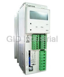
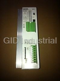

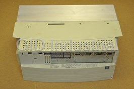


What they say about us
FANTASTIC RESOURCE
One of our top priorities is maintaining our business with precision, and we are constantly looking for affiliates that can help us achieve our goal. With the aid of GID Industrial, our obsolete product management has never been more efficient. They have been a great resource to our company, and have quickly become a go-to supplier on our list!
Bucher Emhart Glass
EXCELLENT SERVICE
With our strict fundamentals and high expectations, we were surprised when we came across GID Industrial and their competitive pricing. When we approached them with our issue, they were incredibly confident in being able to provide us with a seamless solution at the best price for us. GID Industrial quickly understood our needs and provided us with excellent service, as well as fully tested product to ensure what we received would be the right fit for our company.
Fuji
HARD TO FIND A BETTER PROVIDER
Our company provides services to aid in the manufacture of technological products, such as semiconductors and flat panel displays, and often searching for distributors of obsolete product we require can waste time and money. Finding GID Industrial proved to be a great asset to our company, with cost effective solutions and superior knowledge on all of their materials, it’d be hard to find a better provider of obsolete or hard to find products.
Applied Materials
CONSISTENTLY DELIVERS QUALITY SOLUTIONS
Over the years, the equipment used in our company becomes discontinued, but they’re still of great use to us and our customers. Once these products are no longer available through the manufacturer, finding a reliable, quick supplier is a necessity, and luckily for us, GID Industrial has provided the most trustworthy, quality solutions to our obsolete component needs.
Nidec Vamco
TERRIFIC RESOURCE
This company has been a terrific help to us (I work for Trican Well Service) in sourcing the Micron Ram Memory we needed for our Siemens computers. Great service! And great pricing! I know when the product is shipping and when it will arrive, all the way through the ordering process.
Trican Well Service
GO TO SOURCE
When I can't find an obsolete part, I first call GID and they'll come up with my parts every time. Great customer service and follow up as well. Scott emails me from time to time to touch base and see if we're having trouble finding something.....which is often with our 25 yr old equipment.
ConAgra Foods