

 Manufacturers
KEYENCE PJ-V90
Description
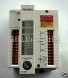
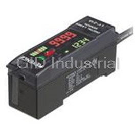
Keyence PJ-V90 - PJ-V Safety Light Curtain Main Controller
Part Number
PJ-V90
Price
Request Quote
Manufacturer
KEYENCE
Lead Time
Request Quote
Category
COMPONENTS
Specifications
[Output] AUX
0.5 A at 125 VAC, 2 A at 30 VDC (resistive load), 0.25 A at 125 VAC (COS ø : 0.3) (inductive load), 1 A at 30 VDC (COS ø : 0.3) (inductive load)
[Output] FSD1, FSD2, SSD
4 A at 230 VAC, 2 A at 30 VDC (resistive load), 2 A at 230 VAC (COS ø : 0.3) (inductive load), 1 A at 30 VDC (COS ø : 0.3) (inductive load)
[Output] Service Life
Mechanical: 10 million operations or more, Electrical: 100,000 operations or more (Use of an RC snubber is recommended for inductive loads.)
Ambient Tempertature
-10 to +55°C
Category
Can be used in U.S.A., Canada, and European countries.
Compliance with International standards
Category 4 ESPE according to EN954-1 (type 4 AOPD according to IEC61496)
Current consumption
PJ-V90+PJ-V20: 350mA PJ-V21: 25mA. PJ-V91+PJ-V20: 110mA PJ-V22: 15mA
Enclosure Rating
IP-20 (Mount controller inside control panel with IP-54 or higher level enclosure rating.)
Material
Polycarbonate
Power Consumption
20 W max. (Including consumption by sensor head)
Power Supply
24 V DC ±10%, Ripple (p-p): 5% max.
Protection Circuit
Power supply section: Reversed polarity protection, surge absorber
Relative Humidity
35 to 95%
Response time / FSD1, FSD2, SSD, AUX
15 ms max. (ON to OFF) (Including sensor head response time)
Sensor head to be combined
PJ-V20, PJ-V21, PJ-V22
Shock
100 m/s2, 328.1'/s2 (approx. 10 G), 16 ms pulses in X, Y, and Z directions, 1000 times each axis.
Signal Input/ Input method
Non - voltage input
Vibration
10 to 55 Hz, 0.7 mm double amplitude in X, Y, and Z directions, 20 times each axis.
Weight
PJ-V90: 520 g, PJ-V91: 150 g
Datasheet

Extracted Text
Cat No PJV-KA-C
Expandable Safety Light Curtain
NEW
Optional Corner Mirror
-
PJ V Series
Dimensions When rotated 45°
Length of
reflective surface
Z
Y X
30
16
0.63"
1.18"
1.18" 0.91"
23
40 30
Specifications
1.57"
Corner mirror
Product name
18
0.71" 21
32 32
1.14"
29 0.83" 1.26" 1.26"
Model OP-35334 OP-35335 OP-35336
1.42"
36
Optical axis
8 to 16 20 to 24 28 to 32
pitch: 20 mm
Applicable No. 1.10" 1.30" 33
28
17.5
of optical axes
Optical axis
0.69"
10 to 12 14 to 16
4 to 8
pitch: 40 mm
Length of
Length of reflective surface 370 mm 14.57" 530 mm 20.87" 690 mm 27.17"
Model XY Z
reflective surface
Applicable sensor combination PJ-V20/V40
370 450 430 416
OP-35334
One mirror 6 m 19.7' 14.57" 17.72" 16.93" 16.38"
Detecting
530
610 590 576
Two mirrors 5.5 m 18.0'
1. OP-35335
distance
20.87"
24.02" 23.23" 22.68"
Three mirrors 5 m 16.4'
690
770 750 736
OP-35336
27.17"
Detection capability 30.31" 29.53" 28.98"
Opaque materials (28 mm 1.10" dia. min.)
Ambient temperature -10 to +55˚C
Relative humidity 35 to 95%
Mirror: Back surface mirror, Housing: Aluminum,
Material
Mounting bracket: Zinc die-cast
Weight Approx. 410 g Approx. 510 g Approx. 610 g
Accessory
Mounting bracket (2 pcs.: OP-31784)
1.Detecting distance is the total distance between the transmitter and receiver by
way of the corner mirrors.
Visit our website for other Keyence products at http://www.keyence.com
Specifications are subject to change without notice.
KEYENCE CORPORATION OF AMERICA
Corporate Office
50 Tice Blvd., Woodcliff Lake, NJ 07675, U.S.A.
Minneapolis Office Phoenix Office
Boston Office Atlanta Office Cincinnati Office
Phone:952-924-9779 Fax:952-249-9143 Phone:602-225-2400 Fax:602-225-2425
Phone:781-453-2244 Fax:781-453-2255 Phone:770-951-1222 Fax:770-951-1958 Phone:513-554-1227 Fax:513-554-1229
New Jersey Office Tampa Office
Michigan Office St. Louis Office Portland Office
Phone:201-291-4000 Fax:201-291-8860 Phone:813-998-9886 Fax:813-998-9887
Phone:734-591-9922 Fax:734-591-1722 Phone:314-275-9174 Fax:314-275-9175 Phone:503-699-0500 Fax:503-699-8400
Pennsylvania Office Cleveland Office Indianapolis Office Texas Office Northern California Office
OSHA ANSI
CUS
Phone:610-768-8993 Fax:610-337-1067 Phone:216-464-7530 Fax:216-464-7540 Phone:317-843-2616 Fax:317-843-2647 Phone:972-733-6790 Fax:972-733-6791 Phone:925-225-1550 Fax:925-225-1440
CATEGORY 4
Charlotte Office Columbus Office Chicago Office Denver Office Los Angeles Office
Phone:704-423-0070 Fax:704-423-0066 Phone:614-799-3400 Fax:614-799-3401 Phone:847-969-0001 Fax:847-969-0453 Phone:303-756-5242 Fax:303-756-8301 Phone:310-851-8635 Fax:310-851-8681
©KEYENCE CORPORATION,1999
PJV-KA-C-3-1099 Printed in Japan
1.1
3.6
8.6"
(220mm)
In-house System Configuration
Controller Expansion
Keyence's revolutionary modular system permits
An inexpensive sub-controller is available for use with a second sensor
in-house custom configurations.This unique
head. A simple connector eliminates any wiring requirement.
feature enables your safety detection
system to adapt to your changing
safety needs.
Space-Saving Design
This ultimate space saving Smallest in its class
An impressive compact size for a full scale safety system.
design is first in its safety
class. The ultra-slim sensor
head and ultra-compact
controller create a new image
in safety light curtain design.
The rugged body is a double-
layered structure of aluminum
lined with steel.
Easy Optical Alignment
The LED bar indicator guides a fast and easy alignment. The number of illuminated
LEDs confirms the signal strength and a color change from red to green indicates an
Optimal Detection Zone
optimal alignment. In case of a detection, the indicators inform the operator of the
The optimal detection zone can be configured in increments
detection status in real time.
( )
of 3.14" 80mm to create a 15 level system as shown below.
The expansion system consists of only three different components,
which allows inventory to be kept to a minimum. An oil-resistant resin protects
the entire lens surface.
Sub-controller
Main controller PJ-V90
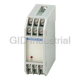
PJ-V91
+
The /- 2.5° narrow-view lens
eliminates reflected light from
surrounding objects.
unit:inch
Minimum detection zone
5.5"
( )
140mm
A stable light reading An unstable light reading A light interruption Abnormal
(insufficient light quantity) detection
Reduced Set-up Time
The sub-controller is easily connected to the main
control unit using a connector. There is no need for
any wiring to a power supply or output lines.
The sub-controller not only reduces set up time but
A sturdy lightweight
also provides a substantial cost savings.
aluminum outer housing
with a wall thickness of
Maximum detection zone
( )
0.06" 1.6 mm .
Easy-to-see LED bar indicators.
49.6"
Mutual Interference
( )
1,260mm
thickness
0.06"
Suppression
( )
1.6mm
When the sub-controller is connected to the main unit
Conventional Models
the suppression function is automatically activated.
Provide either insufficient or excessive protection PJ-V Design
There is no need for any specialized wiring as the two
A specially molded
sensor heads will not interfere with each other.
The design of the inner housing
steel structure.
prevents foreign matter from entering.
Cost effective
Slim, Compact, and Sturdy Construction
Using one main controller and a sub-controller is more
An easy grip alloy angle-adjustment
This space saving compact design is first in its safety class. Although slim in design the
cost effective than using two main controllers.
mounting bracket.
sensor head is extremely durable and can withstand harsh environments. The metallic
construction of the outer housing, inner housing and locking mechanism ensure the
durability of the sensor head and its ability to withstand vibration and impact.
An excessive detection zone
An operator's hand can beyond the application's Allows in-house custom
A highly reliable oil-resistant cable.
reach the hazardous area through requirements must be used to configuration to meet the specific
( ( ) )
• Long operating range up to 22.9' 22.9' 7m 7m
an unguarded area. provide adequate protection. detection needs of each
8 optical axes. 16 optical axes. individual application.
6.5'/16.4'/22.9' (2m/5m/7m)
• Water-resistant IP-65 IP-65 rated enclosure
2 4 5
4.8
3.4
Selections Specifications
Highest Safety Rating
The PJ-V series meets the following international standards
and is accepted worldwide.
OSHA ANSI
CUS
Sensor Head
Expandable Sensor Head
Configuration Examples
Model PJ-V20, 21, 22
• Each unit consists of a transmitter and receiver.
*1
Controller to be combined PJ-V90, PJ-V91
• The end caps are included with the base unit.
When detecting an area of
Detection zone 140 to 1260 mm 5.51" to 49.6"
• The expansion unit B does not require end cap.
780 mm with 40 optical
Number of optical axes 8 to 64 axes
axes,the required units are:
Category 4 rated in accordance
Optical axis pitch 20 mm 0.79"
with the EN standards.
Operating range 7 m 23.0'
PJ-V20 1set
Detection capability Opaque materials (28 mm 1.10" dia. min.)
and
PJ-V21 4sets
Light source Infrared LED (880 nm)
Operating form LIGHT-ON
Indicator Bar of 8 two-color (red and green) LEDs both on transmitter and receiver
*2
±
Effective aperture angle 2.5˚ max. (When operating range is 3 m 9.8' or more)
Enclosure rating IP-65
Ambient light Incandescent lamp: 5,000 lux max, Sunlight: 20,000 lux max
Ambient temperature -10 to +55˚C
Expansion Expansion
Base Unit
Relative humidity 35 to 95%
Unit A Unit B
Vibration 10 to 55 Hz, 0.7 mm double amplitude in X, Y, and Z directions, 20 times each axis.
2 2
Shock 100 m/s 328.1'/s (approx. 10 G), 16 ms pulses in X, Y, and Z directions, 1000 times each axis.
Material Housing: Aluminum, Lens cover: Polyarylate
Weight PJ-V20: 570 g (including End cap: 140 g), PJ-V21: 320 g, PJ-V22: 290 g
2
Transmitter 500 mm 19.69" 4-core cable with connector (0.5 mm , AWG20)
2
Receiver 500 mm 19.69" 5-core cable with connector (0.5 mm , AWG20)
Cable
Transmitter and receiver cable lengths can each be extended up to 21 m 68.9'
Extension
(excluding 500-mm 19.69" length of cable extruded from base unit).
Sensor Detection zone:
*1 The PJ-V91 cannot operate independently. It is a sub-controller connected to the PJ-V90.
5.5 8.6 11.8 14.9 18.1 21.2 24.4 27.5 30.7 33.8 37.0 40.1 43.3 46.4 49.6
inch
*2 In accordance with IEC61496 (EN61496).
Detection Capability:
(mm) ( ) ( ) ( ) ( )
(140) 220 (300) (380) (460) (540) (620) 700 (780) (860) 940 (1020) 1100 (1180) (1260)
20 mm pitch 28 mm in diameter
Number of Optical
Model 8 12 16 20 24 28 32 36 40 44 48 52 56 60 64
Unit Connector Cable
Axes
PJ-VC2T: Approx. 150 g, PJ-VC5T: Approx. 340 g, PJ-VC7T: Approx. 460 g,
PJ-V22 Expansion unit B
4 0 1 0 1 0 1 0 1 0 1 0 1 0 1 0 Weight
PJ-VC2R: Approx. 160 g, PJ-VC5R: Approx. 360 g, PJ-VC7R: Approx. 490 g,
PJ-V21 Expansion unit A
8 0 0 1 1 2 2 3 3 4 4 5 5 6 6 7
PJ-V20 8 1 1 1 1 1 1 1 1 1 1 1 1 1 1 1 Controller
Base unit
Model PJ-V90
Number of units required
Sensor head to be combined PJ-V2x
Power supply 24 V DC ±10%, Ripple (p-p): 5% max.
Controller Connector Cable
Power consumption 20 W max. (Including consumption by sensor head)
Description Application Transmitter Receiver
Model
PJ-V90+PJ-V20: 350mA PJ-V21: 25mA
Current consumption
Length
PJ-V91+PJ-V20: 110mA PJ-V22: 15mA
Model Model
When using
4 A at 230 VAC, 2 A at 30 VDC (resistive load), 2 A at 230 VAC (COS ş = 0.3) (inductive load),
PJ-V90 Main controller
FSD1, FSD2, SSD
a single sensor head
1 A at 30 VDC (COS ş = 0.3) (inductive load)
6.5'(2m) PJ-VC2T PJ-VC2R
0.5 A at 125 VAC, 2 A at 30 VDC (resistive load), 0.25 A at 125 VAC (COS ş = 0.3) (inductive load),
Output
AUX
1 A at 30 VDC (COS ş = 0.3) (inductive load)
PJ-VC5T
16.4'(5m) PJ-VC5R
When using
Mechanical: 10 million operations or more, Electrical: 100,000 operations or more
PJ-V91 Sub-controller
Country/Area Standards Qualifying Organization Marking
two sensor heads
Service life
Complies to the Latest Standards
( ) (Use of an RC snubber is recommended for inductive loads.)
22.9' 7m PJ-VC7T PJ-VC7R
*4
*2
EN 61496-1, 2
Response time FSD1, FSD2, SSD, AUX 15 ms max. (ON to OFF) (Including sensor head response time)
Old Numbers
New Numbers
Europe EN 954-1H
DEMKO *PJ-V91 cannot be used independently. * Transmitter and receiver cable lengths can be expanded separately.
pr.EN50100-1, 2
EN61496-1, 2 The transmitter and receiver cable lengths can each be expanded up to 21 m Signal input Input method Non - voltage input
EN 60204-1
(excluding the length of the 50-cm cable extruding from the base unit.)
pr.EN954-1
EN954-1
*3 Enclosure rating IP-20 (Mount controller inside control panel with IP-54 or higher level enclosure rating.)
*4
pr.IEC61496-1, 2 IEC 61496-1, 2
IEC61916-1, 2
UL
Protection circuit Power supply section: Reversed polarity protection, surge absorber
UL491
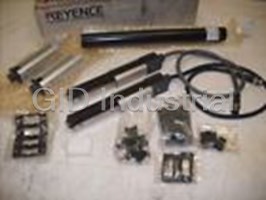
Replacement Parts
Ambient temperature -10 to +55˚C
U.S.A./
All of these parts are supplied with the product, and are also available separately.
OSHA 1910.212
Noise Resistance.
Canada
Relative humidity 35 to 95%
OSHA 1910.217 (C)
Model Description
*1
The PJ-V complies with the noise resistance standards
Vibration 10 to 55 Hz, 0.7 mm double amplitude in X, Y, and Z directions, 20 times each axis.
ANSI B11.1 to B11.19
OP-31608 Test piece(ş28mm)
specified by the EMC directive.
2 2
ANSI R15.06 Shock 100 m /s 328.1'/s (approx. 10 G), 16 ms pulses in X, Y, and Z directions, 1000 times each axis.
OP-31609 Release tool
Mounting brackets
OP-31784 Material Polycarbonate
*1 ANSI and OSHA do not qualify products for compliance. It is the responsibility of the machine
Support brackets
manufacturer to conform to the standards. OP-31785
Weight PJ-V90: 520 g, PJ-V91: 150 g
*2 The mark, when affixed to a product indicates that the product complies with the requirements
End cap
OP-31786
Compliance with
stipulated by EMC directive.
Can be used in U.S.A., Canada, and European countries.
LOCKOUT release key
OP-31787
*3 The mark, when affixed to a product indicates that the product is UL or CSA listed when applicable. international standards
Relay board unit
*4 These standards were still being discussed and modified untill finalized at the end of 1997. Since OP-31788
Test piece OP-31608 Release tool OP-31609 Mounting brackets Support brackets End cap OP-31786
Category Category 4 ESPE according to EN954-1 (type 4 AOPD according to IEC61496)
the PJ-V qualifies for the latest stringent standards, it can be used without worry for an extended period. OP-31784 OP-31785
36 7
1.1
3.6
8.6"
(220mm)
In-house System Configuration
Controller Expansion
Keyence's revolutionary modular system permits
An inexpensive sub-controller is available for use with a second sensor
in-house custom configurations.This unique
head. A simple connector eliminates any wiring requirement.
feature enables your safety detection
system to adapt to your changing
safety needs.
Space-Saving Design
This ultimate space saving Smallest in its class
An impressive compact size for a full scale safety system.
design is first in its safety
class. The ultra-slim sensor
head and ultra-compact
controller create a new image
in safety light curtain design.
The rugged body is a double-
layered structure of aluminum
lined with steel.
Easy Optical Alignment
The LED bar indicator guides a fast and easy alignment. The number of illuminated
LEDs confirms the signal strength and a color change from red to green indicates an
Optimal Detection Zone
optimal alignment. In case of a detection, the indicators inform the operator of the
The optimal detection zone can be configured in increments
detection status in real time.
( )
of 3.14" 80mm to create a 15 level system as shown below.
The expansion system consists of only three different components,
which allows inventory to be kept to a minimum. An oil-resistant resin protects
the entire lens surface.
Sub-controller
Main controller PJ-V90
PJ-V91
+
The /- 2.5° narrow-view lens
eliminates reflected light from
surrounding objects.
unit:inch
Minimum detection zone
5.5"
( )
140mm
A stable light reading An unstable light reading A light interruption Abnormal
(insufficient light quantity) detection
Reduced Set-up Time
The sub-controller is easily connected to the main
control unit using a connector. There is no need for
any wiring to a power supply or output lines.
The sub-controller not only reduces set up time but
A sturdy lightweight
also provides a substantial cost savings.
aluminum outer housing
with a wall thickness of
Maximum detection zone
( )
0.06" 1.6 mm .
Easy-to-see LED bar indicators.
49.6"
Mutual Interference
( )
1,260mm
thickness
0.06"
Suppression
( )
1.6mm
When the sub-controller is connected to the main unit
Conventional Models
the suppression function is automatically activated.
Provide either insufficient or excessive protection PJ-V Design
There is no need for any specialized wiring as the two
A specially molded
sensor heads will not interfere with each other.
The design of the inner housing
steel structure.
prevents foreign matter from entering.
Cost effective
Slim, Compact, and Sturdy Construction
Using one main controller and a sub-controller is more
An easy grip alloy angle-adjustment
This space saving compact design is first in its safety class. Although slim in design the
cost effective than using two main controllers.
mounting bracket.
sensor head is extremely durable and can withstand harsh environments. The metallic
construction of the outer housing, inner housing and locking mechanism ensure the
durability of the sensor head and its ability to withstand vibration and impact.
An excessive detection zone
An operator's hand can beyond the application's Allows in-house custom
A highly reliable oil-resistant cable.
reach the hazardous area through requirements must be used to configuration to meet the specific
( ( ) )
• Long operating range up to 22.9' 22.9' 7m 7m
an unguarded area. provide adequate protection. detection needs of each
8 optical axes. 16 optical axes. individual application.
6.5'/16.4'/22.9' (2m/5m/7m)
• Water-resistant IP-65 IP-65 rated enclosure
2 4 5
4.8
3.4
Selections Specifications
Highest Safety Rating
The PJ-V series meets the following international standards
and is accepted worldwide.
OSHA ANSI
CUS
Sensor Head
Expandable Sensor Head
Configuration Examples
Model PJ-V20, 21, 22
• Each unit consists of a transmitter and receiver.
*1
Controller to be combined PJ-V90, PJ-V91
• The end caps are included with the base unit.
When detecting an area of
Detection zone 140 to 1260 mm 5.51" to 49.6"
• The expansion unit B does not require end cap.
780 mm with 40 optical
Number of optical axes 8 to 64 axes
axes,the required units are:
Category 4 rated in accordance
Optical axis pitch 20 mm 0.79"
with the EN standards.
Operating range 7 m 23.0'
PJ-V20 1set
Detection capability Opaque materials (28 mm 1.10" dia. min.)
and
PJ-V21 4sets
Light source Infrared LED (880 nm)
Operating form LIGHT-ON
Indicator Bar of 8 two-color (red and green) LEDs both on transmitter and receiver
*2
±
Effective aperture angle 2.5˚ max. (When operating range is 3 m 9.8' or more)
Enclosure rating IP-65
Ambient light Incandescent lamp: 5,000 lux max, Sunlight: 20,000 lux max
Ambient temperature -10 to +55˚C
Expansion Expansion
Base Unit
Relative humidity 35 to 95%
Unit A Unit B
Vibration 10 to 55 Hz, 0.7 mm double amplitude in X, Y, and Z directions, 20 times each axis.
2 2
Shock 100 m/s 328.1'/s (approx. 10 G), 16 ms pulses in X, Y, and Z directions, 1000 times each axis.
Material Housing: Aluminum, Lens cover: Polyarylate
Weight PJ-V20: 570 g (including End cap: 140 g), PJ-V21: 320 g, PJ-V22: 290 g
2
Transmitter 500 mm 19.69" 4-core cable with connector (0.5 mm , AWG20)
2
Receiver 500 mm 19.69" 5-core cable with connector (0.5 mm , AWG20)
Cable
Transmitter and receiver cable lengths can each be extended up to 21 m 68.9'
Extension
(excluding 500-mm 19.69" length of cable extruded from base unit).
Sensor Detection zone:
*1 The PJ-V91 cannot operate independently. It is a sub-controller connected to the PJ-V90.
5.5 8.6 11.8 14.9 18.1 21.2 24.4 27.5 30.7 33.8 37.0 40.1 43.3 46.4 49.6
inch
*2 In accordance with IEC61496 (EN61496).
Detection Capability:
(mm) ( ) ( ) ( ) ( )
(140) 220 (300) (380) (460) (540) (620) 700 (780) (860) 940 (1020) 1100 (1180) (1260)
20 mm pitch 28 mm in diameter
Number of Optical
Model 8 12 16 20 24 28 32 36 40 44 48 52 56 60 64
Unit Connector Cable
Axes
PJ-VC2T: Approx. 150 g, PJ-VC5T: Approx. 340 g, PJ-VC7T: Approx. 460 g,
PJ-V22 Expansion unit B
4 0 1 0 1 0 1 0 1 0 1 0 1 0 1 0 Weight
PJ-VC2R: Approx. 160 g, PJ-VC5R: Approx. 360 g, PJ-VC7R: Approx. 490 g,
PJ-V21 Expansion unit A
8 0 0 1 1 2 2 3 3 4 4 5 5 6 6 7
PJ-V20 8 1 1 1 1 1 1 1 1 1 1 1 1 1 1 1 Controller
Base unit
Model PJ-V90
Number of units required
Sensor head to be combined PJ-V2x
Power supply 24 V DC ±10%, Ripple (p-p): 5% max.
Controller Connector Cable
Power consumption 20 W max. (Including consumption by sensor head)
Description Application Transmitter Receiver
Model
PJ-V90+PJ-V20: 350mA PJ-V21: 25mA
Current consumption
Length
PJ-V91+PJ-V20: 110mA PJ-V22: 15mA
Model Model
When using
4 A at 230 VAC, 2 A at 30 VDC (resistive load), 2 A at 230 VAC (COS ş = 0.3) (inductive load),
PJ-V90 Main controller
FSD1, FSD2, SSD
a single sensor head
1 A at 30 VDC (COS ş = 0.3) (inductive load)
6.5'(2m) PJ-VC2T PJ-VC2R
0.5 A at 125 VAC, 2 A at 30 VDC (resistive load), 0.25 A at 125 VAC (COS ş = 0.3) (inductive load),
Output
AUX
1 A at 30 VDC (COS ş = 0.3) (inductive load)
PJ-VC5T
16.4'(5m) PJ-VC5R
When using
Mechanical: 10 million operations or more, Electrical: 100,000 operations or more
PJ-V91 Sub-controller
Country/Area Standards Qualifying Organization Marking
two sensor heads
Service life
Complies to the Latest Standards
( ) (Use of an RC snubber is recommended for inductive loads.)
22.9' 7m PJ-VC7T PJ-VC7R
*4
*2
EN 61496-1, 2
Response time FSD1, FSD2, SSD, AUX 15 ms max. (ON to OFF) (Including sensor head response time)
Old Numbers
New Numbers
Europe EN 954-1H
DEMKO *PJ-V91 cannot be used independently. * Transmitter and receiver cable lengths can be expanded separately.
pr.EN50100-1, 2
EN61496-1, 2 The transmitter and receiver cable lengths can each be expanded up to 21 m Signal input Input method Non - voltage input
EN 60204-1
(excluding the length of the 50-cm cable extruding from the base unit.)
pr.EN954-1
EN954-1
*3 Enclosure rating IP-20 (Mount controller inside control panel with IP-54 or higher level enclosure rating.)
*4
pr.IEC61496-1, 2 IEC 61496-1, 2
IEC61916-1, 2
UL
Protection circuit Power supply section: Reversed polarity protection, surge absorber
UL491
Replacement Parts
Ambient temperature -10 to +55˚C
U.S.A./
All of these parts are supplied with the product, and are also available separately.
OSHA 1910.212
Noise Resistance.
Canada
Relative humidity 35 to 95%
OSHA 1910.217 (C)
Model Description
*1
The PJ-V complies with the noise resistance standards
Vibration 10 to 55 Hz, 0.7 mm double amplitude in X, Y, and Z directions, 20 times each axis.
ANSI B11.1 to B11.19
OP-31608 Test piece(ş28mm)
specified by the EMC directive.
2 2
ANSI R15.06 Shock 100 m /s 328.1'/s (approx. 10 G), 16 ms pulses in X, Y, and Z directions, 1000 times each axis.
OP-31609 Release tool
Mounting brackets
OP-31784 Material Polycarbonate
*1 ANSI and OSHA do not qualify products for compliance. It is the responsibility of the machine
Support brackets
manufacturer to conform to the standards. OP-31785
Weight PJ-V90: 520 g, PJ-V91: 150 g
*2 The mark, when affixed to a product indicates that the product complies with the requirements
End cap
OP-31786
Compliance with
stipulated by EMC directive.
Can be used in U.S.A., Canada, and European countries.
LOCKOUT release key
OP-31787
*3 The mark, when affixed to a product indicates that the product is UL or CSA listed when applicable. international standards
Relay board unit
*4 These standards were still being discussed and modified untill finalized at the end of 1997. Since OP-31788
Test piece OP-31608 Release tool OP-31609 Mounting brackets Support brackets End cap OP-31786
Category Category 4 ESPE according to EN954-1 (type 4 AOPD according to IEC61496)
the PJ-V qualifies for the latest stringent standards, it can be used without worry for an extended period. OP-31784 OP-31785
36 7
Usage Guidelines Dimensions
Unit:mm Inch
Sensor Unit PJ-V20/21/22
Additional Points
For detailed instructions please refer to Rear mounting Side mounting
Number
• Never disassemble the sensor head or controller. 40 22.5 Detection
of XY Z
the instruction manual included with the PJ-V.
1.57" 0.86" zone
optical axes
22
32 17 .5 0.69" 18 0.71"
1.26" 0.87" 8 140 5.51" 240 9.45" 220 8.66" 206 8.11"
• Do not install the power supply or signal lines in the same
12 220 8.66" 320 12.60" 300 11.81" 286 11.26"
conduit as high voltage or power lines.
Dead
Type of Equipment / Machinery 16 300 11.81" 400 15.75" 380 14.96" 366 14.41"
zone
33
1.30"
20 380 14.96" 480 18.90" 460 18.11" 446 17.56"
The PJ-V can be used as a safety sensor on almost all equipment • Be sure to turn off the power supply before starting any wiring.
24 460 18.11" 560 22.05" 540 21.26" 526 20.71"
28 540 21.26" 640 25.20" 620 24.41" 606 23.86"
in the U.S.A., Canada, and Europe. Make all electrical connections in accordance with local electrical
32 620 24.41" 720 28.36" 700 27.56" 686 27.01"
codes and laws.
36 700 27.56" 800 31.50" 780 30.71" 766 30.16"
780 30.71" 880 34.65" 860 33.86" 846 33.31"
40
Sensor Head Expansion Unit
• The LOCKOUT input terminals are shipped short-circuited with a 44 860 33.86" 960 37.80" 940 37.01" 926 36.46"
48 940 37.01" 1040 40.94" 1020 40.16" 1006 39.61"
• Be sure to turn off the power supply before connecting the units.
shorting bar. When using the LOCKOUT input, remove the
Detection
52 1020 40.16" 1120 44.09" 1100 43.31" 1086 42.76"
zone
56 1100 43.31" 1200 47.24" 1180 46.46" 1166 45.91"
shortihg bar.
• If the end cap (top cover) or expansion unit B is not attached,
Y X Z
60 1180 46.46" 1280 50.39" 1260 49.61" 1246 49.06"
25
the PJ-V will not operate.
0.98" 64 1260 49.61" 1360 53.54" 1340 52.80" 1326 52.20"
• The transmitter and receiver cable lengths can each be expanded 790 ± 30
790 ± 30
31.1" ± 1. 18"
31.1" ± 1. 18"
up to 21 m, excluding the length of the 50-cm cable extruding
• Do not confuse the transmitter with the receiver when
Mounting bracket
Intermediate support
from the base unit. Combine the 2-m, 5-m, and 7-m special
connecting the units. Insert the unit until it is secured and check
470 ± 30
470 ± 30 ( )
Accessory for PJ-V20
18.5" ± 1. 18" 18.5" ± 1.18"
connector cables as required. The number of core wires for
that it is not disconnected.
11
Frequently asked questions
What makes Elite.Parts unique?

What kind of warranty will the PJ-V90 have?
Which carriers does Elite.Parts work with?
Will Elite.Parts sell to me even though I live outside the USA?
I have a preferred payment method. Will Elite.Parts accept it?
Why buy from GID?

Quality
We are industry veterans who take pride in our work

Protection
Avoid the dangers of risky trading in the gray market

Access
Our network of suppliers is ready and at your disposal

Savings
Maintain legacy systems to prevent costly downtime

Speed
Time is of the essence, and we are respectful of yours
Related Products
Request a Quote

The quote request has been received
Close

Facing challenges or have inquiries? Feel free to contact us!
Call Us +1-469-283-2440
What they say about us
FANTASTIC RESOURCE
One of our top priorities is maintaining our business with precision, and we are constantly looking for affiliates that can help us achieve our goal. With the aid of GID Industrial, our obsolete product management has never been more efficient. They have been a great resource to our company, and have quickly become a go-to supplier on our list!
Bucher Emhart Glass
EXCELLENT SERVICE
With our strict fundamentals and high expectations, we were surprised when we came across GID Industrial and their competitive pricing. When we approached them with our issue, they were incredibly confident in being able to provide us with a seamless solution at the best price for us. GID Industrial quickly understood our needs and provided us with excellent service, as well as fully tested product to ensure what we received would be the right fit for our company.
Fuji
HARD TO FIND A BETTER PROVIDER
Our company provides services to aid in the manufacture of technological products, such as semiconductors and flat panel displays, and often searching for distributors of obsolete product we require can waste time and money. Finding GID Industrial proved to be a great asset to our company, with cost effective solutions and superior knowledge on all of their materials, it’d be hard to find a better provider of obsolete or hard to find products.
Applied Materials
CONSISTENTLY DELIVERS QUALITY SOLUTIONS
Over the years, the equipment used in our company becomes discontinued, but they’re still of great use to us and our customers. Once these products are no longer available through the manufacturer, finding a reliable, quick supplier is a necessity, and luckily for us, GID Industrial has provided the most trustworthy, quality solutions to our obsolete component needs.
Nidec Vamco
TERRIFIC RESOURCE
This company has been a terrific help to us (I work for Trican Well Service) in sourcing the Micron Ram Memory we needed for our Siemens computers. Great service! And great pricing! I know when the product is shipping and when it will arrive, all the way through the ordering process.
Trican Well Service
GO TO SOURCE
When I can't find an obsolete part, I first call GID and they'll come up with my parts every time. Great customer service and follow up as well. Scott emails me from time to time to touch base and see if we're having trouble finding something.....which is often with our 25 yr old equipment.
ConAgra Foods