

 Manufacturers
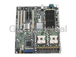
INTEL SE7520BD2V
Description
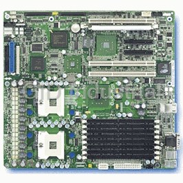
Intel SE7520BD2V CPU Board. Intel Server Board, Support for Dual Intel Xeon Processors, Intel E7520 Chipset, PCI Express I/O Interconnect Technology, Single-channel Ultra320/LVD SCSI
Part Number
SE7520BD2V
Price
Request Quote
Manufacturer
INTEL
Lead Time
Request Quote
Category
COMPONENTS
Specifications
Chipset
Intel E7520 chipset | Supports 800 MHz Front Side Bus (FSB) | Intel E7520 Memory Controller Hub (MCH) | Intel 6700PXH 64-bit PCI Hub | Intel 82801ER I/O Controller Hub5 (ICH-5R)
Expansion Slots
Six full-length, full-height PCI expansion slots | Slot 1 and Slot 2: PCI-X 64-bit/100 MHz | Slot 3: PCI 32-bit/33MHz | Slot 4: PCI Express x8 with x4 speeds | Slot 5: PCI Express x8 (not on product codes SE7520BD2V and SE7520BD2VD2) | Slot 6: PCI-X 64-bit/133-MHz
Form Factor
SSI-EEB3.5 compliant form factor | Board size 12 inches by 13 inches
Hard Disk Drive
Two serial ATA 150 ports | Support for entry-level RAID functionality (LSI Logic integrated mirroring and integrated striping)
I/O Control
Super I/O controller chip | Two stacked and interchangeable PS/2 compatible keyboard/mouse ports | One external serial port on the rear I/O port area (Serial A) | One serial port header to provide a second, optional serial port (Serial B) | One IDE connector supporting up to two ATA-100 compatible devices | One standard floppy drive interface
LAN
Dual integrated 10/100/1000 MB on-board Ethernet connectors | One Marvell 88E8050 10/100/1000 LAN | One Intel 82541PI 10/100/1000 LAN
Memory
Eight DIMM sockets | DDR2-400 | 240-pin ECC Registered DIMMs | Supported DIMM sizes: 256 MB, 512 MB, 1 GB, 2 GB | 16 GB Maximum | Dual channel architecture | Memory Mirroring | Memory Sparing
Processor
Intel Xeon
Processors
Up to two Intel Xeon processors with an FC-mPGA4 using Socket 604, and an 800-MHz Front Side Bus (FSB)
Video
Integrated on-board ATI Rage XL SVGA video controller | 8 MB SDRAM video memory | SVGA video port
Features
- Dual memory channels for up to 4.26 GB/sec (DDR 266) or up to 6.4 GB/sec (DDR 333) combined bandwidth
- Dual-channel Serial ATA with support for RAID 0 and 1
- Integrated graphics: ATI RAGE XL SVGA PCI video controller with 8 MB of video memory
- Intel E7520 chipset
- Intel Management Module upgrade connector - Support for Intel Management Module Professional Edition and Intel Management Module Advanced Edition (optional upgrades)
- Intel Server Management 8 - Onboard Platform Instrumentation
- One IDE connector supporting two ATA 100 IDE channels
- Optional integrated single- or dual-channel Ultra320 SCSI with support for RAID 0 and 1
- Six independent PCI buses and up to six9 adapter slots: One PCI Express x810, One PCI Express x411, One PCI-X 133MHz, Two PCI-X 100MHz, One PCI 32-bit/33MHz 5V
- Support for two Intel Xeon processors with an 800MHz system bus
- Support for up to 12 GB of Registered ECC DDR 266/3338 SDRAM
- Two Gigabit Ethernet connections: One Intel 82541PI Gigabit Ethernet controller & One Marvell Yukon-EC 88E8050 PCI Express Gigabit Ethernet Controller
Datasheet

Extracted Text
Intel® Server Board SE7520BD2
User Guide
®
A Guide for Technically Qualified Assemblers of Intel Identified
Subassemblies/Products
Order Number: C51518-007
Disclaimer
®
Information in this document is provided in connection with Intel products. No license, express or implied, by estoppel or
otherwise, to any intellectual property rights is granted by this document. Except as provided in Intel’s Terms and Conditions
of Sale for such products, Intel assumes no liability whatsoever, and Intel disclaims any express or implied warranty, relating
to sale and/or use of Intel products including liability or warranties relating to fitness for a particular purpose, merchantability,
or infringement of any patent, copyright or other intellectual property right. Intel products are not designed, intended or
authorized for use in any medical, life saving, or life sustaining applications or for any other application in which the failure of
the Intel product could create a situation where personal injury or death may occur. Intel may make changes to
specifications and product descriptions at any time, without notice.
Intel server boards contain a number of high-density VLSI and power delivery components that need adequate airflow for
cooling. Intel’s own chassis are designed and tested to meet the intended thermal requirements of these components when
the fully integrated system is used together. It is the responsibility of the system integrator that chooses not to use Intel
developed server building blocks to consult vendor datasheets and operating parameters to determine the amount of airflow
required for their specific application and environmental conditions. Intel Corporation can not be held responsible if
components fail or the server board does not operate correctly when used outside any of their published operating or non-
operating limits.
Intel, Intel Pentium, and Intel Xeon are trademarks or registered trademarks of Intel Corporation or its subsidiaries in the
United States and other countries.
* Other names and brands may be claimed as the property of others.
Copyright © 2004 - 2005, Intel Corporation. All Rights Reserved
ii
Preface
About this Manual
®
Thank you for purchasing and using the Intel Server Board SE7520BD2. Six versions of this
server board are available. These boards have the following product codes:
Product code SE7520BD2
Product code SE7520BD2SCSI
Product code SE7520BD2V
Product code SE7520BD2SCSID2
Product code SE7520BD2VD2
Product code SE7520BD2SATAD2
This manual applies to each of these products.
NOTES
✏
Most diagrams in this manual show product code SE7520BD2. Where
necessary to complete a procedure, differences are noted.
This manual is written for system technicians who are responsible for troubleshooting, upgrading,
and repairing this server board. This document provides a brief overview of the features of the
board/chassis, a list of accessories or other components you may need, troubleshooting information,
®
and instructions on how to add and replace components on the Intel Server Board SE7520BD2.
For the latest version of this manual, refer to
http://support.intel.com/support/motherboards/server/SE7520BD2/.
Manual Organization
®
Chapter 1 provides a brief overview of the Intel Server Board SE7520BD2. In this chapter, you
will find a list of the server board features, photos of the product, and product diagrams to help you
identify components and their locations.
Chapter 2 provides instructions on adding and replacing components. Use this chapter for step-by-
step instructions and diagrams for installing or replacing components such as the memory,
processor, and the battery, among other components.
Chapter 3 provides instructions on using the utilities that are shipped with the board or that may be
required to update the system. This includes how to navigate through the BIOS Setup screens, how
to perform a BIOS update, and how to reset the password or CMOS. Information about the specific
BIOS settings and screens is available in the Intel® Server Board SE7520BD2 Technical Product
Specification.
Chapter 4 provides troubleshooting information. In this chapter, you will find BIOS error messages
and POST code messages. You will also find suggestions for performing troubleshooting activities
to identify the source of a problem.
Intel® Server Board SE7520BD2 User Guide iii
Preface
Product Accessories
®
These server boards are compatible with the following Intel Server Chassis:
®
Intel Server Chassis SC5300
®
Intel Server Chassis SC5300 BRP
®
Intel Server Chassis SC5300 LX
®
Intel Entry Server Chassis SC5275-E
®
Intel Entry Server Chassis SC5295-E DP
®
Intel Entry Server Chassis SC5295-E BRP
NOTES
✏
The server chassis support varies by the version of the server board. To make
sure you have the right server board / chassis combination, see “Server
Chassis”.
You may need or want to purchase one or more of the following accessory items for your server:
Processor
Memory DIMM
Hard drive
Floppy drive/CD-ROM drive/DVD-ROM drive
RAID controller
Operating system
For information about which accessories, memory, processors, and third-party hardware have been
tested and can be used with your board, look for the Tested Hardware and Operating System List.
For ordering information for the server board, check the Spares and Configuration Guide
Document.
Additional Information and Software
If you need more information about this product or information about the accessories that can be
used with this server board, use the following resources:
For this information or software Obtain this document / software
For in-depth technical information about this Intel® Server Board SE7520BD2 Technical Product Specification
product, including BIOS settings and chipset
information
®
If you just received this product and need to Intel Server Board SE7520BD2 Quick Start User’s Guide
install it located in the product box or to obtain a newer version, use this
link: Quick Start User’s Guide.
Accessories or other Intel server products Spares and Configuration Guide Document
Hardware (peripheral boards, adapter cards) Tested Hardware and Operating System List
and operating systems that have been
tested with this product
Chassis that have been tested with this Reference Chassis List
product
iv
Preface
Processors that have been tested with this Supported Processor List
product
DIMMs that have been tested with this Tested Memory List
product
To make sure your system falls within the Power Budget Tool
allowed power budget
®
For software to manage your Intel Server Intel® Server Management Software
For firmware, BIOS updates, and drivers Download Finder
To obtain the documents or software mentioned in the above table and for the latest product
technical information, please go to:
http://support.intel.com/support/motherboards/server/SE7520BD2
Safety Information
Emissions Disclaimer
To ensure EMC compliance with your local regional rules and regulations, the final configuration
of your end system product may require additional EMC compliance testing. For more information
please contact your local Intel Representative.
See “Regulatory and Integration Information” for product safety compliance and EMC regulatory
compliance information. This is an FCC Class A device. Integration of it into a Class B chassis
does not result in a Class B device.
Intended Uses
This product was evaluated as Information Technology Equipment (ITE), which may be installed in
offices, schools, computer rooms, and similar commercial type locations. The suitability of this
product for other product categories and environments (such as: medical, industrial,
telecommunications, NEBS, residential, alarm systems, test equipment, etc.), other than an ITE
application, may require further evaluation
EMC Testing
Before computer integration, make sure that the chassis, power supply, and other modules have
passed EMC testing using a server board with a microprocessor from the same family (or higher)
and operating at the same (or higher) speed as the microprocessor used on this server board.
Warnings
Heed safety information: Before working with your server product,
whether you are using this guide or any other resource as a reference, pay
close attention to the safety instructions. You must adhere to the assembly
instructions in this guide to ensure and maintain compliance with existing
product certifications and approvals. Use only the described, regulated
components specified in this guide. Use of other products / components will
void the UL listing and other regulatory approvals of the product and will
most likely result in noncompliance with product regulations in the region(s)
in which the product is sold.
v
Preface
System power on/off: The power button DOES NOT turn off the system
AC power. To remove power from system, you must unplug the AC power
cord from the wall outlet. Make sure the AC power cord is unplugged before
you open the chassis, add, or remove any components.
Hazardous conditions, devices and cables: Hazardous electrical
conditions may be present on power, telephone, and communication cables.
Turn off the server and disconnect the power cord, telecommunications
systems, networks, and modems attached to the server before opening it.
Otherwise, personal injury or equipment damage can result.
Electrostatic discharge (ESD) and ESD protection: ESD can damage
disk drives, boards, and other parts. We recommend that you perform all
procedures in this chapter only at an ESD workstation. If one is not available,
provide some ESD protection by wearing an antistatic wrist strap attached to
chassis ground any unpainted metal surface on your server when
handling parts.
ESD and handling boards: Always handle boards carefully. They can be
extremely sensitive to ESD. Hold boards only by their edges. After removing
a board from its protective wrapper or from the server, place the board
component side up on a grounded, static free surface. Use a conductive foam
pad if available but not the board wrapper. Do not slide board over any
surface.
Installing or removing jumpers: A jumper is a small plastic encased
conductor that slips over two jumper pins. Some jumpers have a small tab on
top that you can grip with your fingertips or with a pair of fine needle nosed
pliers. If your jumpers do not have such a tab, take care when using needle
nosed pliers to remove or install a jumper; grip the narrow sides of the
jumper with the pliers, never the wide sides. Gripping the wide sides can
damage the contacts inside the jumper, causing intermittent problems with
the function controlled by that jumper. Take care to grip with, but not
squeeze, the pliers or other tool you use to remove a jumper, or you may
bend or break the stake pins on the board.
Safety Cautions
Read all caution and safety statements in this document before performing
any of the instructions. See also Intel Server Boards and Server Chassis
Safety Information on the Deployment CD and/or at
http://support.intel.com/support/motherboards/server/sb/CS-010770.htm
Wichtige Sicherheitshinweise
Lesen Sie zunächst sämtliche Warn- und Sicherheitshinweise in diesem
Dokument, bevor Sie eine der Anweisungen ausführen. Beachten Sie hierzu
auch die Sicherheitshinweise zu Intel-Serverplatinen und -Servergehäusen
auf der Ressourcen-CD oder unter
http://support.intel.com/support/motherboards/server/sb/CS-010770.htm
vi
Preface
要安全指导
在执行任何指令之前,请阅读本文档中的所有注意事项及安全声明。参
见 Resource CD (资源光盘) 和/或
http://support.intel.com/support/motherboards/server/sb/CS-010770.htm
上的 Intel Server Boards and Server Chassis Safety Information
(《 Intel 服务器主板与服务器机箱安全信息》)。
Consignes de sécurité
Lisez attention toutes les consignes de sécurité et les mises en garde
indiquées dans ce document avant de suivre toute instruction. Consultez Intel
Server Boards and Server Chassis Safety Information sur le CD Resource
CD ou bien rendez-vous sur le site
http://support.intel.com/support/motherboards/server/sb/CS-010770.htm
Instrucciones de seguridad importantes
Lea todas las declaraciones de seguridad y precaución de este documento
antes de realizar cualquiera de las instrucciones. Vea Intel Server Boards and
Server Chassis Safety Information en el CD Resource y/o en
http://support.intel.com/support/motherboards/server/sb/CS-010770.htm
AVVERTENZA: Italiano
PASSI DI SICUREZZA: Qualora si rimuovano le coperture del telaio per accedere all’interno
del sistema, seguire i seguenti passi:
1. Spegnere tutti i dispositivi periferici collegati al sistema.
2. Spegnere il sistema, usando il pulsante spento/acceso dell’interruttore del sistema.
3. Togliere tutte le spine dei cavi del sistema dalle prese elettriche.
4. Identificare e sconnettere tutti i cavi attaccati ai collegamenti I/O od alle prese
installate sul retro del sistema.
5. Qualora si tocchino i componenti, proteggersi dallo scarico elettrostatico (SES),
portando un cinghia anti-statica da polso che è attaccata alla presa a terra del telaio
del sistema – qualsiasi superficie non dipinta – .
6. Non far operare il sistema quando il telaio è senza le coperture.
Se il sistema è stato a lungo in funzione, il microprocessore e il dissipatore di calore
potrebbero essere surriscaldati. Fare attenzione alla presenza di piedini appuntiti e parti
taglienti sulle schede e sul telaio. È consigliabile l'uso di guanti di protezione.
vii
Preface
viii
Contents
1 Server Board Features................................................................................. 13
Connector and Header Locations .........................................................................................18
Product Codes SE7520BD2, SE7520BD2SCSI, SE7520BD2V ..................................18
Product Codes SE7520BD2SCSID2, SE7520BD2VD2, SE7520BD2SATAD2 ...........20
Configuration Jumpers..........................................................................................................22
Back Panel Connectors.........................................................................................................23
Hardware Requirements .......................................................................................................24
Server Chassis.............................................................................................................24
Processor .....................................................................................................................24
Memory .......................................................................................................................25
2 Hardware Installations and Upgrades........................................................ 28
Before You Begin..................................................................................................................28
Tools and Supplies Needed..................................................................................................28
Installing and Removing Memory..........................................................................................28
Installing DIMMs...........................................................................................................29
Removing DIMMs.........................................................................................................30
Installing or Replacing the Processor....................................................................................30
Installing the Processor................................................................................................31
Removing a Processor.................................................................................................34
Installing or Removing a PCI Card........................................................................................34
Replacing the Backup Battery...............................................................................................35
3 Server Utilities .............................................................................................. 37
Using the BIOS Setup Utility .................................................................................................37
Starting Setup ..............................................................................................................37
If You Cannot Access Setup ........................................................................................37
Setup Menus ................................................................................................................37
Upgrading the BIOS..............................................................................................................39
Preparing for the Upgrade............................................................................................39
Preparing Media and Performing the BIOS Upgrade...................................................40
Crisis Recovery Diskette ..............................................................................................41
Recovering the BIOS ............................................................................................................42
Recovering the BIOS with the Crisis Recovery Diskette..............................................42
Clearing the Password..........................................................................................................44
Clearing the CMOS...............................................................................................................45
4 Troubleshooting ........................................................................................... 46
Resetting the System............................................................................................................46
Problems following Initial System Installation .......................................................................46
First Steps Checklist.....................................................................................................46
Hardware Diagnostic Testing................................................................................................47
Confirming Loading of the Operating System ..............................................................48
Specific Problems and Corrective Actions ............................................................................48
Power Light Does Not Light..........................................................................................48
Intel® Server Board SE7520BD2 User Guide ix
Contents
No Characters Appear on Screen ................................................................................49
Characters Are Distorted or Incorrect...........................................................................50
System Cooling Fans Do Not Rotate Properly.............................................................50
Diskette Drive Activity Light Does Not Light.................................................................50
CD-ROM Drive or DVD-ROM Drive Activity Light Does Not Light ...............................51
Cannot Connect to a Server.........................................................................................51
Problems with Network.................................................................................................51
System Boots when Installing PCI Card.......................................................................52
Problems with Newly Installed Application Software....................................................52
Problems with Application Software that Ran Correctly Earlier....................................52
Devices are not Recognized under Device Manager (Windows* Operating System)..53
Hard Drive(s) Are Not Recognized...............................................................................53
Bootable CD-ROM Is Not Detected..............................................................................53
LED Information ....................................................................................................................53
BIOS POST Beep Codes......................................................................................................54
Boot Block Error Beep Codes ......................................................................................54
POST Error Beep Codes..............................................................................................54
Regulatory and Compliance Information........................................................ 56
Product Regulatory Compliance ...........................................................................................56
Product Safety Compliance..........................................................................................56
Product EMC Compliance – Class A Compliance........................................................56
Certifications/Registrations/Declarations......................................................................57
Product Regulatory Compliance Markings...................................................................57
Electromagnetic Compatibility Notices..................................................................................58
FCC (USA) ...................................................................................................................58
Industry Canada (ICES-003)........................................................................................59
Europe (CE Declaration of Conformity)........................................................................59
Taiwan Declaration of Conformity (BSMI)....................................................................59
Korean Compliance (RRL) ...........................................................................................59
Getting Help ....................................................................................................... 60
®
Intel Server Issue Report Form....................................................................... 62
x
Contents
Figures
®
Figure 1. Intel Server Board SE7520BD2 ................................................................................13
Figure 2. Product Codes SE7520BD2, SE7520BD2SCSI, and SE7520BD2V Connector and
Header Locations.................................................................................................................19
Figure 3. Product Codes SE7520BD2SCSID2, SE7520BD2VD2, and SE7520BD2SATAD2
Connector and Header Locations........................................................................................21
Figure 4. Configuration Jumper Location....................................................................................22
Figure 5. Back Panel Connectors ...............................................................................................23
Figure 6. Installing Memory.........................................................................................................29
Figure 7. Opening Socket Lever .................................................................................................31
Figure 8. Inserting Processor......................................................................................................31
Figure 9. Closing Socket Lever...................................................................................................32
Figure 10. Installing the Heat Sink ..............................................................................................33
Figure 11. Replacing the Backup Battery ...................................................................................36
Figure 12. Recovery Boot Jumper ..............................................................................................43
Figure 13. Password Clear Jumper ............................................................................................44
Figure 14. Clear CMOS Jumper .................................................................................................45
Tables
Table 1. Server Board Varieties..................................................................................................14
Table 2. Server Board Features..................................................................................................17
Table 3. Configuration Jumpers..................................................................................................22
Table 4. NIC LEDs ......................................................................................................................23
Table 5. Intel® Server Chassis Supported for each Server Board SE7520BD2 Product Code..24
Table 6. Keyboard Commands ...................................................................................................38
Table 7. Boot Block Error Beep Codes .......................................................................................54
Table 8. POST Error Beep Codes ..............................................................................................54
Table 9. BIOS Beep Codes.........................................................................................................55
Table 10. Product Certification Markings ....................................................................................57
xi
Contents
xii
1 Server Board Features
®
This chapter briefly describes the main features of the Intel Server Board SE7520BD2, provides a
photograph of the product, a list of the server board features, and diagrams showing the location of
important components and connections on the server board.
®
Figure 1. Intel Server Board SE7520BD2
Six product codes for the Server Board SE7520BD2 are available. The following table provides an
overview of the differences between them, by product code.
Intel® Server Board SE7520BD2 User Guide 13
Server Board Features
Table 1. Server Board Varieties
Product Code Memory PCI SCSI SATA USB Connections
Product code Six DIMM sockets One PCI Express* x8 N/A Dual serial ATA Five:
SE7520BD2 channels with support
DDR 266/333 One PCI Express x4 - Three at rear of
for RAID 0 and 1.
board
72-bit, 184-pin DIMMs One PCI-X* 133MHz
One IDE connector
- Two at front of
Supported DIMM sizes: 256 Two PCI-X 100MHz
supporting two
board
MB, 512 MB, 1 GB, 2 GB, 4
One PCI 32-bit / 33MHz 5V
ATA/100 IDE
GB
channels.
24 GB Maximum (when 4 GB
DIMMs are available)
Dual channel architecture
Memory Mirroring
Memory Sparing
Product code Eight DIMM sockets One PCI Express* x8 N/A Dual serial ATA Four:
SE7520BD2SATAD2 channels with support
DDR2-400 One PCI Express x4 - Two at rear of
for RAID 0 and 1.
board
240-pin ECC Registered One PCI-X* 133MHz
One IDE connector
DIMMs - Two at front of
Two PCI-X 100MHz
supporting two
board
Supported DIMM sizes: 256
One PCI 32-bit / 33MHz 5V
ATA/100 IDE
MB, 512 MB, 1 GB, 2 GB
channels.
16 GB Maximum
Dual channel architecture
Memory Mirroring
Memory Sparing
Continued
14
Server Board Features
Table 1. Server Board Varieties (continued)
Product Code Memory PCI SCSI SATA USB Connections
Product code Six DIMM sockets One PCI Express* x8 Two Ultra- Dual serial ATA Five:
SE7520BD2SCSI 320/LVD channels with support
DDR 266/333 One PCI Express x4 - Three at rear of
channels via the for RAID 0 and 1.
board
72-bit, 184-pin DIMMs One PCI-X* 133MHz
LSI* 53C1030
One IDE connector
- Two at front of
Supported DIMM sizes: Two PCI-X 100MHz
SCSI controller
supporting two
board
256MB, 512MB, 1GB, 2GB,
One PCI 32-bit / 33MHz 5V
ATA/100 IDE
4GB
channels.
24 GB Maximum (when 4GB
DIMMs are available)
Dual channel architecture
Memory Mirroring
Memory Sparing
Product code Eight DIMM sockets One PCI Express* x8 Two Ultra- Dual serial ATA Four:
SE7520BD2SCSID2 320/LVD channels with support
DDR2-400 One PCI Express x4 - Two at rear of
channels via the for RAID 0 and 1.
board
240-pin ECC Registered One PCI-X* 133MHz
LSI 53C1030
One IDE connector
DIMMs - Two at front of
Two PCI-X 100MHz
SCSI controller
supporting two
board
Supported DIMM sizes: 256
One PCI 32-bit / 33MHz 5V
ATA/100 IDE
MB, 512 MB, 1 GB, 2 GB
channels.
16 GB Maximum
Dual channel architecture
Memory Mirroring
Memory Sparing
Continued
15
Server Board Features
Table 1. Server Board Varieties (continued)
Product Code Memory PCI SCSI SATA USB Connections
Product code Six DIMM sockets One PCI Express x4 One Ultra- Dual serial ATA Four:
SE7520BD2V 320/LVD channel channels with support
DDR 266/333 One PCI-X 133MHz - Two at rear of
via either the LSI* for RAID 0 and 1.
board
72-bit, 184-pin DIMMs Two PCI-X 100MHz
53C1020 or LSI*
One IDE connector
- Two at front of
Supported DIMM sizes: One PCI 32-bit / 33MHz 5V
53C1020A SCSI
supporting two
board
256MB, 512MB, 1GB, 2GB,
controller
ATA/100 IDE
4GB
channels.
24 GB Maximum (when 4 GB
DIMMs are available)
Dual channel architecture
Memory Mirroring
Memory Sparing
Product code Eight DIMM sockets One PCI Express x4 One Ultra- Dual serial ATA Four:
SE7520BD2VD2 320/LVD channel channels with support
DDR2-400 One PCI-X 133MHz - Two at rear of
via either the LSI for RAID 0 and 1.
board
240-pin ECC Registered Two PCI-X 100MHz
53C1020 or LSI
One IDE connector
DIMMs - Two at front of
One PCI 32-bit / 33MHz 5V
53C1020A SCSI
supporting two
board
Supported DIMM sizes: 256
controller
ATA/100 IDE
MB, 512 MB, 1 GB, 2 GB
channels.
16 GB Maximum
Dual channel architecture
Memory Mirroring
Memory Sparing
16
Server Board Features
Table 2 summarizes the major features of the server board. See Table 1 for additional information.
Table 2. Server Board Features
Feature Description
®
Processors Up to two Intel Xeon™ processors with an FC-mPGA4 using Socket 604, and an
800-MHz Front Side Bus (FSB)
Memory See Table 1
®
Chipset Intel E7520 chipset:
Supports 800 MHz Front Side Bus (FSB)
®
Intel E7520 Memory Controller Hub (MCH)
®
Intel 6700PXH 64-bit PCI Hub
®
Intel 82801ER I/O Controller Hub5 (ICH-5R)
I/O Control Super I/O controller chip that provides:
Two stacked and interchangeable PS/2 compatible keyboard/mouse ports
USB ports: See Table 1
One external serial port on the rear I/O port area (Serial A)
One serial port header to provide a second, optional serial port (Serial B)
One IDE connector supporting up to two ATA-100 compatible devices
One standard floppy drive interface
Integrated on-board ATI Rage* XL SVGA video controller.
Video
8 MB SDRAM video memory
SVGA video port
Two serial ATA 150 ports
Hard Disk Drive
Support for entry-level RAID functionality (LSI* Logic integrated mirroring and
integrated striping)
See Table 1
LAN Dual integrated 10/100/1000 MB on-board Ethernet connectors
One Marvell* 88E8050 10/100/1000 LAN
®
One Intel 82541PI 10/100/1000 LAN
Expansion Slots Six full-length, full-height PCI expansion slots.
Slot 1 and Slot 2: PCI-X* 64-bit/100 MHz
Slot 3: PCI 32-bit/33MHz
Slot 4: PCI Express* x8 with x4 speeds
Slot 5: PCI Express x8 (not on product codes SE7520BD2V and
SE7520BD2VD2)
Slot 6: PCI-X* 64-bit/133-MHz
Six multi-speed system fan headers.
Fans
Two single-speed CPU fan headers.
Server Management National Semiconductor* PC87431M controller to provide monitoring, alerting
and logging of critical sensor information.
®
Intel Light-Guided Diagnostics on critical FRU devices, such as processors,
memory, and power (not on product codes SE7520BD2V and SE7520BD2VD2)
®
Custom front panel LCD connectors for use with the Intel Local Control Panel
®
Intel Management Module Professional or Advanced
SSI-EEB3.5 compliant form factor
Form Factor
Board size 12 inches by 13 inches
17
Server Board Features
Connector and Header Locations
Product Codes SE7520BD2, SE7520BD2SCSI, SE7520BD2V
G L
A B C D E F H I J K M
N
TT
O
P
SS
RR
QQ
Q
PP
R
OO
NN
MM
LL CPU 2 CPU 1
KK
JJ
II
HH
GG
FF
DD BB Z X W
EE AA V U T S
CC Y
TP00718
18
Server Board Features
A Chassis Intrusion P CPU Power Connector GG SATA A1
B, Left PCI-X* 100 Slot Q DIMM Sockets HH HSBP B
B, Right PCI-X 100 Slot (MROMB) R CPU 1 Fan Header II Front Panel Connector
C Super I/O S CPU 1 JJ SCSI Channel A
D PCI Slot 32/33 T CPU 2 KK System Fan 1 (3-pin)
®
E ATI* Rage XL Graphics Controller U Intel Management Module LL System Fan 3 (6-pin)
Connector
F, Left x8 (x4speed) PCI-Express* Slot V IDE Connector MM System Fan 4 (6-pin)
F, Right x8 PCI-Express Slot W Floppy Connector NN OEM RMC
®
G Intel 82541P1 (10/100/1000) X System Fan 2 (3-pin) OO ICH5R
H PCI-X 133 Slot Y System Fan 2 (2-pin) PP SCSI Channel B
I Battery Z System Fan 1 (2-pin) QQ LSI* 53C1030 SCSI
Controller
J ICMB Connector AA HSBP A RR CPU 2 Fan Header
K System Fan 5 BB Front Panel USB SS MCH
L System Fan 6 CC Front Panel LCP TT PHX
M System I/O Connectors DD IPMB UU Serial B Header
N Auxiliary Power Connector EE SATA A2
O Main Power Connector FF Speaker
Note: F, Right (x8 PCI Express), NN (OEM RMC), and PP (SCSI Channel B) are not available on product codes SE7520BD2V.
QQ (LSI* 53C1030 SCSI Controller) is not available on product code SE7520BD2.
Figure 2. Product Codes SE7520BD2, SE7520BD2SCSI, and SE7520BD2V Connector and
Header Locations
19
Server Board Features
Product Codes SE7520BD2SCSID2, SE7520BD2VD2,
SE7520BD2SATAD2
G L
A B C D E F H I J K M
N
TT
O
P
SS
RR
O
QQ
Q
PP
R
OO
NN
MM
LL CPU 2 CPU 1
KK
JJ
II
HH
GG
FF
DD BB Z X W
EE AA V U T S
CC Y
TP01688
20
Server Board Features
A Chassis Intrusion P CPU Power Connector GG SATA A1
B, Left PCI-X* 100 Slot Q DIMM Sockets HH HSBP B
B, Right PCI-X 100 Slot (MROMB) R CPU 1 Fan Header II Front Panel Connector
C Super I/O S CPU 1 JJ SCSI Channel A
D PCI Slot 32/33 T CPU 2 KK System Fan 1 (3-pin)
®
E ATI* Rage XL Graphics Controller U Intel Management LL System Fan 3 (6-pin)
Module Connector
F, Left x8 (x4speed) PCI-Express* Slot V IDE Connector MM System Fan 4 (6-pin)
F, Right x8 PCI-Express Slot W Floppy Connector NN OEM RMC
®
G Intel 82541P1 (10/100/1000) X System Fan 2 (3-pin) OO ICH5R
H PCI-X 133 Slot Y System Fan 2 (2-pin) PP SCSI Channel B
I Battery Z System Fan 1 (2-pin) QQ LSI* 53C1030 SCSI
Controller
J ICMB Connector AA HSBP A RR CPU 2 Fan Header
K System Fan 5 BB Front Panel USB SS MCH
L System Fan 6 CC Front Panel LCP TT PHX
M System I/O Connectors DD IPMB UU Serial B Header
N Auxiliary Power Connector EE SATA A2
O Main Power Connector FF Speaker
Note: F, Right (x8 PCI Express), NN (OEM RMC), and PP (SCSI Channel B) are not available on product codes
SE7520BD2VD2. QQ (LSI* 53C1030 SCSI Controller) is not available on product code SE7520BD2SATAD2.
Figure 3. Product Codes SE7520BD2SCSID2, SE7520BD2VD2, and SE7520BD2SATAD2
Connector and Header Locations
21
Server Board Features
Configuration Jumpers
BIOS
SEL
Normal
Bank 0
3
J1B1
RECOVERY
BOOT
J4H1
CMOS
FRB
CLR
HALT
3
3
J2H1
J4H3 J4H2
PASSWORD
CLEAR
TP00723
Figure 4. Configuration Jumper Location
Table 3. Configuration Jumpers
Jumper Name Pins What happens at system reset…
CMOS Clear 1-2 BMC Control: These pins should be jumpered for normal operation.
(J2H1)
2-3 Force Erase: If these pins are jumpered, the CMOS settings will be cleared on the next
reset. These pins should not be jumpered for normal operation.
Password Clear OFF Protect: These pins should not be jumpered for normal operation.
(J4H3)
ON Erase: If these pins are jumpered, administrator and user passwords will be cleared on
the next reset. These pins should not be jumpered for normal operation.
BIOS Recovery OFF Normal Boot: These pins should not be jumpered for normal operation
(J4H1)
ON Recovery Boot: If these pins are jumpered, the system will attempt to recover the
BIOS by loading the BIOS code into the flash device from a floppy disk. This jumper is
typically used when the BIOS has become corrupted. These pins should not be
jumpered for normal operation.
22
Server Board Features
Back Panel Connectors
F
D
H
A
B C E G I
TP00719
A USB3 (see note)* D Mouse G Video
B USB2 E Keyboard H NIC1 (Management port)
C USB1 F Serial A I NIC2
Note: USB3 is available only on product codes SE7520BD2 and SE7520BD2SCSI
Figure 5. Back Panel Connectors
®
The NIC LEDs at the right and left of the NICs provide the following information. See the Intel
Server Board SE7520BD2 Technical Product Specification for POST code errors.
Table 4. NIC LEDs
LED LED State Description
Off No network connection is in place
Left LED
Solid Green Network connection is in place
Blinking Green Transmit/receive activity
Off 10 Mbps connection (if left LED is on or blinking)
Right LED Solid Green 100 Mbps connection
Solid Amber 1000 Mbps connection
23
Server Board Features
Hardware Requirements
To avoid integration difficulties and possible board damage, your system must meet the
requirements outlined below. For a list of qualified components, see the links under “Additional
Information and Software”.
Server Chassis
The following table shows the product codes for the Server Board SE7520BD2 and the product
codes for the Intel Server Chassis into which the various versions of the board can be installed. If
you are using a non-Intel chassis, see your chassis documentation for support information.
®
Table 5. Intel Server Chassis Supported for each Server Board SE7520BD2 Product Code
SC5275E SC5300 SC5300BRP SC5300LX SC5295DP SC5295BRP
SE7520BD2 Supported Supported Supported Supported Not Not
supported supported
SE7520BD2SCSI Supported Supported Supported Supported Not Not
supported supported
SE7520BD2V Supported Supported Supported Supported Not Not
supported supported
SE7520BD2SATAD2 Supported Supported Supported Supported Supported Supported
SE7520BD2SCSID2 Supported Supported Supported Supported Supported Supported
SE7520BD2VD2 Supported Supported Supported Supported Supported Supported
Processor
® ®
The Intel Server Board SE7520BD2 (all product codes) supports up to two Intel Xeon™
processors with an FC-mPGA4 using Socket 604, and an 800-MHz Front Side Bus (FSB) with
frequencies starting at 2.8 GHz using the 90-nanometer technology. Previous generations of the
®
Intel Xeon™ processors are not supported.
When two processors are installed, both must be of identical revision, core voltage, cache size, and
bus/core speed. When a single processor is installed, it must be in the socket labeled CPU1.
For a link to the complete list of supported processors, see:
http://support.intel.com/support/motherboards/server/se7520bd2/sb/CS-013540.htm
24
Server Board Features
Memory
For a list of supported memory DIMMs, see:
http://support.intel.com/support/motherboards/server/se7520bd2/sb/CS-013543.htm.
Product Codes SE7520BD2, SE7520BD2SCSI, and SE7520BD2V
Product codes SE7520BD2, SE7520BD2SCSI, and SE7520BD2V include three banks of DIMMs
across two channels. Channel A consists of DIMMs 1A, 2A, and 3A. Channel B consists of
DIMMs 1B, 2B, and 3B. Bank 1 (DIMMs 1B and 1A) is closest to the edge of the server board.
DIMMs must be identical within each bank.
The minimum allowed memory is 256 MB, using a single 256 MB DIMM in DIMM slot 1B. The
system operates in single channel when only a single DIMM is installed. The maximum allowed
usable memory is 24 GB of DDR 266 and 16 MB of DDR333, using 4 GB DIMMs.
DIMMs must meet the following requirements:
Use only 184-pin, DDR-266/333 ECC, registered DDR DIMM modules
Have a DIMM organization x72 ECC
i
Support the following sizes: 256 MB, 512 MB, 1 GB, 2 GB, 4GB
®
DDR-333 memory is only supported with BGA package memory on the Intel Server Board
SE7520BD2 (product codes SE7520BD2, SE7520BD2SCSO, SE7520BD2V). TSOP SDRAM
packages will not be supported on DDR-333 DIMMs on these product codes.
A minimum of one 256MB DIMM is required in DIMM socket 1B. This uses single-channel
interleave. However, for dual-channel interleave, providing optimum performance, a minimum
of two DIMMs should be installed in DIMM sockets 1A and 1B. Except for the option of
installing a single DIMM in socket 1B, DIMMs must be installed in pairs and populated as
follows:
DIMM1A and DIMM 1B: Populate these two sockets together first
DIMM 2A and DIMM 2B: Populate these sockets in addition to DIMM 1A and DIMM 2A
if four DIMMs are to be used.
DIMM 3A and DIMM 3B: Populate these sockets after DIMM 1A, DIMM 1B, DIMM 2A,
and DIMM 2B have been populated.
25
Server Board Features
®
Intel Server Boards SE7520BD2SCSID2, SE7520BD2SATAD2, and
SE7520BD2VD2
Product codes SE7520BD2SCSID2, SE7520BD2SATAD2, and SE7520BD2VD2 include four
banks of DIMMs across two channels. Channel A consists of DIMMs 1A, 2A, 3A, and 4A.
Channel B consists of DIMMs 1B, 2B, 3B, and 4B. Bank 1 (DIMMs 1B and 1A) is closest to the
edge of the server board. DIMMs must be identical within each bank.
The minimum allowed memory is 256 MB, using a single 256 MB DIMM in DIMM slot 1B. The
system operates in single channel when only a single DIMM is installed. The maximum allowed
usable memory is 16 GB of DDR2-400, using 2 GB DIMMs.
DIMMs must meet the following requirements:
Use only 240-pin, DDR2-400 ECC, registered DIMM modules
Have a DIMM organization x72 ECC
Support the following sizes: 256 MB, 512 MB, 1 GB, 2 GB
A minimum of one 256MB DIMM is required in DIMM socket 1B. This uses single-channel
interleave. However, for dual-channel interleave, providing optimum performance, a minimum
of two DIMMs should be installed in DIMM sockets 1A and 1B. Except for the option of
installing a single DIMM in socket 1B, DIMMs must be installed in pairs and populated as
follows:
DIMM1A and DIMM 1B: Populate these two sockets together first
DIMM 2A and DIMM 2B: Populate these sockets in addition to DIMM 1A and DIMM 2A
if four DIMMs are to be used.
DIMM 3A and DIMM 3B: Populate these sockets after DIMM 1A, DIMM 1B, DIMM 2A,
and DIMM 2B have been populated.
DIMM 4A and DIMM 4B: Populate these sockets after DIMM 1A, DIMM 1B, DIMM 2A,
DIMM 2B, DIMM 3A, and DIMM 3B have been populated.
Memory Mirroring and Memory On-line Sparing
®
The Intel E7520 chipset includes hardware that supports memory mirroring and memory on-line
sparing. Both memory mirroring and memory on-line sparing provide a way to prevent data loss in
case a DIMM fails.
With memory mirroring the system maintains two copies of all data in the memory subsystem. If a
DIMM fails, the data is not lost because the second copy of the data is available from the mirrored
DIMM. The system will not fail due to memory error unless both the primary and the mirrored
copy of the data become corrupt at the same time.
In a mirrored system, the maximum usable memory is one-half of the installed memory, with a
minimum of four DIMMs installed. Since the data is duplicated across DIMMs, it means that up to
four DIMMs are actively in use at any one time. If six 2 GB DIMMs are installed, the maximum
usable memory is 6 GB (three of the installed DIMMs). The remaining three 2 GB DIMMs are used
for mirroring.
26
Server Board Features
For memory on-line sparing, one DIMM per channel is used as the memory spare. If a DIMM
begins to fail, the content of the failing DIMM is copied to the spare DIMM in that channel. When
all of the data is copied to the spare DIMM, the primary DIMM is removed from service and the
spare DIMM takes its place. When memory on-line sparing is used, the spare DIMMs must be
equal to or larger than the largest in-service DIMM in that channel.
For additional information, see the Intel® Server Board SE7520BD2 Technical Product
Specification.
Power Supply
The minimum power supply required depends on the server chassis into which the server board is
installed. Your supply must provide a minimum of 1.2 A of 5 V standby current or the board will
not boot.
For the Intel Entry Server Chassis SC5295-E DP, a minimum 450W power supply is required.
For the Intel Entry Server Chassis SC5295-E BRP, a minimum 500W power supply is required.
For the Intel Entry Server Chassis SC5300, a minimum 600W power supply is required.
For the Intel Entry Server Chassis SC5275-E, a minimum 600W power supply is required.
Use the power budget tool to determine the minimum power supply for your system, based on all
installed components. For a link to the power budget utility, see “Additional Information and
Software”.
27
2 Hardware Installations and Upgrades
Before You Begin
Before working with your server product, pay close attention to the “Safety Information” at
the beginning of this manual.
NOTES
✏
Most diagrams in this manual show product code SE7520BD2. Where
necessary to complete a procedure, differences are noted.
Tools and Supplies Needed
*
Phillips (cross head) screwdriver (#1 bit and #2 bit)
Needle-nosed pliers
A ruler
Pen or pencil
Anti-static wrist strap and conductive foam pad (recommended)
Installing and Removing Memory
The silkscreen on the board for the DIMMs displays DIMM1B, DIMM1A, DIMM2B, DIMM2A,
DIMM3B, DIMM3A starting from the edge of the board. See “Memory” for a discussion of the
memory requirements and options. See “Additional Information and Software” for a link to the list
of tested DIMMs for this server board.
Intel® Server Board SE7520BD2 User Guide 28
Hardware Installations and Upgrades
Installing DIMMs
To install DIMMs, follow these steps:
1. Observe the safety and ESD precautions at the beginning of this book.
2. Turn off all peripheral devices connected to the server. Turn off the server.
3. Disconnect the AC power cord from the server.
4. Remove the chassis cover. See your chassis documentation for instructions.
5. Locate the DIMM sockets. See Figure 6.
NOTES
✏
The diagram below shows product code SE7520BD2. If you are using a
Server Board SE7520BD2 that supports DDR2 memory DIMMs, your server
board will have eight DIMM sockets instead of the six pictured below. From
left to right, the eight DIMM sockets are numbered DIMM 4A, DIMM 4B,
DIMM 3A, DIMM3B, DIMM2A, DIMM2B, DIMM1A, DIMM1B. Begin
populating your memory with DIMM 1B.
DIMM 2A DIMM 2B
DIMM 3B DIMM 1A
DIMM 3A DIMM 1B
TP00722
Figure 6. Installing Memory
29
Hardware Installations and Upgrades
6. Make sure the clips at either end of the DIMM socket(s) are pushed outward to the open
position.
7. Holding the DIMM by the edges, remove it from its anti-static package.
8. Position the DIMM above the socket. Align the small notch in the bottom edge of the DIMM
with the key in the socket.
9. Insert the bottom edge of the DIMM into the socket.
10. When the DIMM is inserted, carefully push straight down on the top edge of the DIMM until
the retaining clips snap into place. Make sure the clips are firmly in place.
11. Replace the chassis cover and reconnect the AC power cord.
Removing DIMMs
To remove a DIMM, follow these steps:
1. Observe the safety and ESD precautions at the beginning of this book.
2. Turn off all peripheral devices connected to the server. Turn off the server.
3. Remove the AC power cord from the server.
4. Remove the chassis cover.
5. Gently spread the retaining clips at each end of the socket. The DIMM lifts from the socket.
6. Holding the DIMM by the edges, lift it from the socket, and store it in an anti-static package.
7. Reinstall and reconnect any parts you removed or disconnected to reach the DIMM sockets.
8. Replace the chassis cover and reconnect the AC power cord.
Installing or Replacing the Processor
CAUTIONS
Processor must be appropriate: You may damage the server board if
you install a processor that is inappropriate for your server. See Supported
Processor List for compatible processor(s).
ESD and handling processors: Reduce the risk of electrostatic
discharge (ESD) damage to the processor by doing the following: (1) Touch
the metal chassis before touching the processor or server board. Keep part of
your body in contact with the metal chassis to dissipate the static charge
while handling the processor. (2) Avoid moving around unnecessarily.
30
Hardware Installations and Upgrades
Installing the Processor
To install a processor, follow these instructions:
1. Observe the safety and ESD precautions at the beginning of this book.
2. Turn off all peripheral devices connected to the server. Turn off the server.
3. Disconnect the AC power cord from the server.
4. Remove the chassis cover and locate the processor sockets.
5. Locate the processor socket and raise the socket handle completely.
TP00725
Figure 7. Opening Socket Lever
6. Align the pins of the processor with the socket, and insert the processor into the socket.
NOTE
✏
Make sure the alignment triangle mark and the alignment triangle cutout
align correctly.
TP00864
Figure 8. Inserting Processor
31
Hardware Installations and Upgrades
7. Lower the socket lever completely.
TP00865
Figure 9. Closing Socket Lever
Installing the Heat Sink(s)
1. The heat sink has Thermal Interface Material (TIM) located on the bottom of it. Use caution
when you unpack the heat sink so you do not damage the TIM.
2. Set the heat sink over the processor, lining up the four captive screws with the four posts
surrounding the processor.
3. Loosely screw in the captive screws on the heat sink corners in a diagonal manner. Do not fully
tighten one screw before tightening another.
4. Gradually and equally tighten each captive screw until all screws are tight.
NOTE
✏
Boxed processor thermal solutions differ depending on the chassis. See the
boxed processor documentation for specifc instructions for the thermal
solution.
32
Hardware Installations and Upgrades
Note:
Heat sink styles
may differ.
TP00721
Figure 10. Installing the Heat Sink
33
Heat Sink Retainer [CEK Spring]
Server Board Cutaway
Hardware Installations and Upgrades
Removing a Processor
1. Observe the safety and ESD precautions at the beginning of this book.
2. Turn off all peripheral devices connected to the server. Turn off the server.
3. Remove the AC power cord from the server.
4. Remove the chassis cover.
5. Unplug the processor fan cable from the server board.
6. Loosen the four captive screws on the corners of the heat sink.
7. Twist the heat sink slightly to break the seal between the heat sink and the processor.
8. Lift the heat sink from the processor. If it does not pull up easily, twist the heat sink again. Do
not force the heat sink from the processor. Doing so could damage the processor.
9. Lift the processor lever.
10. Remove the processor.
11. If installing a replacement processor, see “Installing the Processor”. Otherwise, reinstall the
chassis cover.
Installing or Removing a PCI Card
Peripherals and add-in cards are not included with your system and must be purchased separately. If
a low profile card is installed in the standard full-height riser card slot, it must be equipped with a
standard full-height PCI mounting bracket.
WARNING
Do not attempt to remove a PCI card without turning off the system
first.
1. Remove the chassis cover.
2. See the chassis Quick Start User’s Guide for instructions on removing any chassis cooling
ducts prior to installing or removing a PCI add-in card.
3. Install (or remove) the PCI add-in card.
4. See the chassis Quick Start User’s Guide for instructions on re-installing any chassis cooling
ducts.
5. Re-install the chassis cover.
34
Hardware Installations and Upgrades
Replacing the Backup Battery
The lithium battery on the server board powers the RTC for up to 10 years in the absence of power.
When the battery starts to weaken, it loses voltage, and the server settings stored in CMOS RAM in
the RTC (for example, the date and time) may be wrong. Contact your customer service
representative or dealer for a list of approved devices.
WARNING
Danger of explosion if battery is incorrectly replaced. Replace only with
the same or equivalent type recommended by the equipment
manufacturer. Discard used batteries according to manufacturer’s
instructions.
ADVARSEL!
Lithiumbatteri - Eksplosionsfare ved fejlagtig håndtering. Udskiftning
må kun ske med batteri af samme fabrikat og type. Levér det brugte
batteri tilbage til leverandøren.
ADVARSEL
Lithiumbatteri - Eksplosjonsfare. Ved utskifting benyttes kun batteri
som anbefalt av apparatfabrikanten. Brukt batteri returneres
apparatleverandøren.
VARNING
Explosionsfara vid felaktigt batteribyte. Använd samma batterityp eller
en ekvivalent typ som rekommenderas av apparattillverkaren. Kassera
använt batteri enligt fabrikantens instruktion.
VAROITUS
Paristo voi räjähtää, jos se on virheellisesti asennettu. Vaihda paristo
ainoastaan laitevalmistajan suosittelemaan tyyppiin. Hävitä käytetty
paristo valmistajan ohjeiden mukaisesti.
1 Observe the safety and ESD precautions at the beginning of this book.
2 Turn off all peripheral devices connected to the server. Turn off the server.
3 Disconnect the AC power cord from the server.
4 Remove the chassis cover and locate the battery.
5 Push the metal lever over the top of the battery to the side to disengage it from the battery.
6 While holding the lever away from the battery, lift the battery from its socket.
35
Hardware Installations and Upgrades
TP00724
Figure 11. Replacing the Backup Battery
7 Dispose of the old battery according to local ordinance.
8 Remove the new lithium battery from its package, and observe the correct polarity. The flat
side of the battery that has a “+” on it must face toward the DIMM slots.
9 Insert the battery in the socket.
10 Close the chassis.
11 Run Setup to restore the configuration settings to the RTC.
36
3 Server Utilities
Using the BIOS Setup Utility
This section describes the BIOS Setup Utility options, which is used to change server configuration
defaults. You can run BIOS Setup with or without an operating system present. See the Intel®
Server Board SE7520BD2 Technical Product Specification for additional details about specific
BIOS setup screens.
Starting Setup
You can enter and start BIOS Setup under several conditions:
When you turn on the server, after POST completes the memory test
When you have moved the CMOS jumper on the server board to the “Clear CMOS” position
(enabled)
In the two conditions listed above, after rebooting, you will see this prompt:
Press
Frequently asked questions
What makes Elite.Parts unique?

What kind of warranty will the SE7520BD2V have?
Which carriers does Elite.Parts work with?
Will Elite.Parts sell to me even though I live outside the USA?
I have a preferred payment method. Will Elite.Parts accept it?
Why buy from GID?

Quality
We are industry veterans who take pride in our work

Protection
Avoid the dangers of risky trading in the gray market

Access
Our network of suppliers is ready and at your disposal

Savings
Maintain legacy systems to prevent costly downtime

Speed
Time is of the essence, and we are respectful of yours
Related Products
BX80526F633128 SL3W9
Intel PMD26605001AA 266 MHz CPU Board
INTEL RG82865G SL743 Graphics Memory Controller Hub (GMCH)
Request a Quote

The quote request has been received
Close

Facing challenges or have inquiries? Feel free to contact us!
Call Us +1-469-283-2440
What they say about us
FANTASTIC RESOURCE
One of our top priorities is maintaining our business with precision, and we are constantly looking for affiliates that can help us achieve our goal. With the aid of GID Industrial, our obsolete product management has never been more efficient. They have been a great resource to our company, and have quickly become a go-to supplier on our list!
Bucher Emhart Glass
EXCELLENT SERVICE
With our strict fundamentals and high expectations, we were surprised when we came across GID Industrial and their competitive pricing. When we approached them with our issue, they were incredibly confident in being able to provide us with a seamless solution at the best price for us. GID Industrial quickly understood our needs and provided us with excellent service, as well as fully tested product to ensure what we received would be the right fit for our company.
Fuji
HARD TO FIND A BETTER PROVIDER
Our company provides services to aid in the manufacture of technological products, such as semiconductors and flat panel displays, and often searching for distributors of obsolete product we require can waste time and money. Finding GID Industrial proved to be a great asset to our company, with cost effective solutions and superior knowledge on all of their materials, it’d be hard to find a better provider of obsolete or hard to find products.
Applied Materials
CONSISTENTLY DELIVERS QUALITY SOLUTIONS
Over the years, the equipment used in our company becomes discontinued, but they’re still of great use to us and our customers. Once these products are no longer available through the manufacturer, finding a reliable, quick supplier is a necessity, and luckily for us, GID Industrial has provided the most trustworthy, quality solutions to our obsolete component needs.
Nidec Vamco
TERRIFIC RESOURCE
This company has been a terrific help to us (I work for Trican Well Service) in sourcing the Micron Ram Memory we needed for our Siemens computers. Great service! And great pricing! I know when the product is shipping and when it will arrive, all the way through the ordering process.
Trican Well Service
GO TO SOURCE
When I can't find an obsolete part, I first call GID and they'll come up with my parts every time. Great customer service and follow up as well. Scott emails me from time to time to touch base and see if we're having trouble finding something.....which is often with our 25 yr old equipment.
ConAgra Foods