

 Manufacturers
IEI EBC-1000G
Description
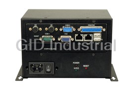
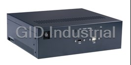
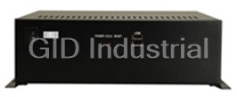
Embedded Chassis for WAFER Series SBC
Part Number
EBC-1000G
Price
Request Quote
Manufacturer
IEI
Lead Time
Request Quote
Category
INDUSTRIAL COMPUTER CHASSIS » EMBEDDED
Specifications
Buttons
Power switch
Color
B: Black
Construction
Metal
Cooling Fans
1 x 4 cm
Dimensions (DxWxH)
130mm x 172.2mm x 116mm
Drive Bays
1 x 2.5" HDD
Indicators
Power, HDD
Operating Temperature
0~50°C
Operation Humidity
10% ~ 90%
SBC Form Factor
3.5" WAFER series SBC
Weight (Net/Gross)
1.2kg / 2.2kg
Features
- 1 x 2.5" HDD drive capacity
- 1 x 4cm cooling fan
- AC/DC power supply compatible
- RoHS compliant design
Datasheet

Extracted Text
EBC-1000G Embedded Chassis Version: 1.1 Quick Installation Guide PACKING LIST When you unpack the chassis, make sure the following items have been shipped. � 1 x Quick Installation Guide � 1 x Power cord � 2 x Base plates � 1 x Screw set � 1 x Fan bracket � 1 x Plastic pillar ABOUT THE EBC-1000G � 1 x Cable set The heavy-duty steel EBC-1000G compact embedded industrial � 1 x Cable tie chassis is designed to operate reliably in industrial environments where it will be exposed to dust, wide temperature variations, shocks DETAILS OF INCLUDED SCREWS and vibrations. The attached screw set includes five screw types. Screws SPECIFICATION used for chassis installation are shown below. � SBC Form Factor: 3.5” WAFER series SBC � Construction: Metal � Cooling: 1 x 4cm fan � Drive Bay: o 1 x 2.5” Internal HDD � Dimensions (DxWxH): o 130mm x 172.2mm x 116mm 1 2 3 4 5 � Operating Temperature: 0~50°C Screw Label Peripherals/Parts � Relative Humidity: 50%~90% (refer to the picture above) � Vibration: 2.5” HDD 1 o Operating Random Vibration Mode:Meet Power Supply Unit 5 MIL-STD-810F 514.5C-1 standard Base plate 3 o Non-Operating Sine Mode:5-17Hz, 0.1” double SBC 3 2 amplitude displacement.17-640Hz, 1.5G acceleration peak to peak. Ground Wire 3 � Shock: Fan Bracket 4 o Operating Shock Half-Sine Wave Shock Table 1: Screws for Peripheral/Parts 3G: 11ms: 3 shocks per axis: Vertical / Transverse / Longitudinal. o Non-Operation Shock Half-Sine Wave Shock 10G: 11ms: 3 shocks per axis: Vertical / Transverse / Longitudinal. EBC-1000G QIG IEI Technology Corp. Page 1 DIMENSION DRAWING The dimensions of the EBC-1000G are shown below. MS KB USB LAN LAN VGA COM Figure 1: Dimension Drawing (measurement units: millimeter) EBC-1000G QIG IEI Technology Corp. Page 2 INSTALLATION STEPS To install the EBC-1000G chassis, the following installation steps must be completed: Step 1: Unpack the chassis. Step 2: Remove the cover. Step 3: Remove the Internal bracket. Step 4: Install the PSU. Figure 3: Top Cover Retention Screws at the Rear Step 5: Install the internal 2.5” HDD. Step 2: Remove the top cover gently.Step 0: Step 6: Install the SBC (Single Board Computer). Step 7: Install the I/O bracket. STEP 3: INTERNAL BRACKET REMOVAL Step 8: Reinstall the Internal bracket. The internal bracket divides the EBC-1000G chassis into the upper compartment and the lower compartment. To remove the Internal Step 9: Connect the cables. bracket, remove the four Internal bracket retention screws, two from each side of the chassis. Step 10: Install the I/O connectors. Step 11: Reinstall the top cover. Step 12: Install the base plates.Step 0: The installation steps outlined above are described in detail below. Please refer to the relevant section. STEP 1: UNPACK The EBC-1000G is shipped in a plastic bag that is placed inside a cardboard box. When you unpack the chassis you must: � Make sure all the items listed in the PACKING LIST section are present. Figure 4: Internal bracket Retention Screws � Make sure the chassis has not been damaged in any way. STEP 4:POWER SUPPLY UNIT (PSU) STEP 2: REMOVE THE TOP COVER INSTALLATION The top cover is secured to the chassis with six retention screws, two at the rear, one on the right side, one on the left Compatible IEI PSUs are listed in table 2 on page 4. and two on the top of the chassis. The PSU is secured to the lower compartment of EBC-1000G Step 1: Remove all six top cover retention screws from the top, chassis. To install a compatible PSU, please follow the steps below: rear, left and right sides of the chassis. Step 1: Connect the PSU cables to the terminal blocks on the PSU. Make sure the input PSU cables connected to the power socket and the output PSU cables are correctly connected to the PSU. The power cable pin definitions are shown in the following drawings. 5CM BLACK 20¡ Ó 1cm L BLACK N White E Green Figure 2: Top Cover Retention Screws on the Top and Sides Cable Tie Pin Assignment 10cm Label E Green and Yellow Figure 5: Input PSU Cable Pin Definitions EBC-1000G QIG IEI Technology Corp. Page 3 Output Range Model No. Input Type Watt +3.3V +5V +12V1 +12V2 -5V -12V +5Vsb ACE-890A-RS AC AT 86W N/A 10A 2.5A N/A N/A 0.5A N/A ACE-890AP-R20-RS AC AT 86W N/A 10A 2.5A N/A N/A 0.5A N/A ACE-890V-RS DC 12V AT 72W N/A 9A 2A N/A N/A 0.3A N/A ACE-890C-RS DC 24V AT 86W N/A 10A 2.5A N/A N/A 0.5A N/A ACE-890T-RS DC 48V AT 86W N/A 10A 2.5A N/A N/A 0.5A N/A ACE-890P-RS DC 110V AT 86W N/A 10A 2.5A N/A N/A 0.5A N/A Table 2: Compatible IEI PSUs 1.+12V (Yellow) 2.GND(Black) STEP 5: 2.5” HDD INSTALLATION The EBC-1000G chassis can support one 2.5” HDD on the Internal 20CM bracket. To install a 2.5” HDD, follow the steps below: 1.+12V (Yellow) 2.GND(Black) Step 1: Position the 2.5” HDD in the 2.5” HDD bay. Make sure the PCB board faces the bottom of the Internal bracket 20CM +12V(Yellow)1 +12V and the IDE/SATA connector faces the rear of the 1 GND(Black) +12V (Yellow) 2 GND Internal bracket. GND 2 GND(Black) GND(Black)3 +5V 3 GND(Black) +5V(Red) 4 4 +5v(Red) Pin Assignment Label Figure 6: Output PSU Cables Pin Definitions Figure 9: 2.5”HDD Position Step 2: Align the four 2.5” HDD retention screw holes on the sides of the 2.5” HDD with the four retention screw holes on the sides of the 2.5” HDD drive bay in the Figure 7: Connect the Power Cables to the Terminal Blocks Internal bracket. Step 3: Insert four retention screws, two into each side of the Step 2: Mount the PSU onto the lower compartment base. 2.5” HDD, to secure the 2.5” HDD to the Internal Step 3: To secure the PSU to the lower compartment, insert bracket. four retention screws through the bottom surface of the lower compartment into the four PSU retention screw holes. Step 0: Figure 10: 2.5”HDD Retention Screws Figure 8: PSU Retention Screws Step 4: Connect the 2.5” HDD ribbon cable.Step 0: EBC-1000G QIG IEI Technology Corp. Page 4 15CM Step 3: Align the retention screw holes in the SBC with the four copper pillar retention screw holes. STEP 6: SBC INSTALLATION Step 4: Insert four retention screws to secure the SBC to the Compatible IEI SBCs are listed in the table below: chassis. Step 0: SBC Model CPU ® STEP 7: I/O BRACKET INSTALLATION ® WAFER-C400-RS ULV Intel Celeron 400MHz ® ® WAFER-9371A ULV Intel Celeron 400/650MHz The EBC-1000G chassis supports four SBC I/O brackets for the ® ® ® WAFER-6612 Intel Pentium M/Celeron M CPU seven compatible IEI SBCs. The user can choose the corresponding ® WAFER-LUKE VIA LUKE 1GHz/533MHz I/O bracket according to the installed SBC. The I/O brackets pictures ® WAFER-MARK VIA MARK 533/800 MHz and the corresponding compatible IEI SBC models are shown in the ® WAFER-LX AMD Geode LX800 500MHz table below. ® WAFER-GX AMD Geode GX466 333MHz I/O Bracket SBC Model Table 3: Compatible SBC Modules WAFER-C400-RS To install an SBC, please follow the instructions below: Step 1: Insert four copper pillars into the Internal bracket. BK-C400-RS WAFER-9371A BK-9371-RS WAFER-6612 BK-6612-RS WAFER-LUKE Figure 11: Copper Pillars WAFER-MARK WAFER-LX WAFER-GX BK-LX800-RS NOTE: Table 4: I/O Brackets and Compatible IEI SBCs One of the WAFER-6612 SBC retention screw holes cannot be The corresponding I/O bracket must be installed before the Internal perfectly aligned with the copper pillar retention screw hole. To bracket is reinstalled. To do this, follow the steps below: install a WAFER-6612 SBC, one of the copper pillars has to be Step 1: Install the corresponding I/O bracket at the front of the replaced by a plastic pillar stuck to the Internal bracket. EBC-1000G chassis. Make sure the words on the I/O bracket face the front of the chassis. Step 2: To secure the I/O bracket to the chassis, insert four retention screws, two into the top and two into the bottom of the I/O bracket. Step 0: Figure 12: WAFER-6612 Plastic Pillar Step 2: Mount the SBC onto the copper pillars. Make sure the I/O connectors face the front of the Internal bracket. Figure 14: I/O Bracket Retention Screws STEP 8: INTERNAL BRACKET REINSTALLATION After the corresponding I/O bracket is installed, the Internal bracket can be installed. To do this, follow the steps below: Step 1: Run the 2.5” HDD ribbon cable, power LED, power switch, reset switch and HDD LED cables through the Figure 13: I/O Connectors Direction hole in the left side of the Internal bracket. EBC-1000G QIG IEI Technology Corp. Page 5 Step 7: Reinsert the four previously removed Internal bracket retention screws. Step 8: Connect the PSU and the 2.5” HDD ribbon cable to the SBC. Figure 15: The Hole in the Right Side of the Internal bracket Step 2: Connect the PSU cable to the fan power cable. Step 3: Run the SBC power cable through the hole in the rear of the Internal bracket. Figure 19: SBC Power Cable and 2.5”HDD Ribbon Cable Step 9: Connect the reset switch, HDD LED and power LED cables to the SBC. The cables provided with the chassis are introduced in STEP 9: CABLING. Step 0: STEP 9: CABLING The EBC-1000G chassis front panel has: Figure 16: The Hole in the Rear of the Internal bracket o 1 x Power LED o 1 x HDD LED Step 4: Remove all the barrel screws before the Internal o 1 x Reset button bracket is reinstalled. o 1 x Power switch Step 5: Reinstall the Internal bracket. Make sure the I/O o 1 x Power Socket connectors are installed into the corresponding holes in To connect the power switch and power socket, refer to STEP 4: the I/O bracket. POWER SUPPLY UNIT (PSU) INSTALLATION. The other components are all connected to the SBC with cables. The cables provided with the chassis are listed below. No. Name 1 Power LED cable 1 Reset Switch cable Figure 17: I/O Connectors in the Corresponding Holes 1 HDD LED cable Step 6: To secure the COM 1 and VGA connectors to the I/O connector bracket, insert four barrel screws, two into each I/O connector. 1 2.4mm to 2.0mm adapter cable 1 Pin header to box header adapter cable Table 5: Chassis Connectors To correctly connect these cables, please refer to the following steps. STEP 9A: FRONT PANEL CABLING 1 Use these steps to connect the chassis front panel LEDs and reset Figure 18: I/O Connector Barrel Screws switch to the following SBCs: EBC-1000G QIG IEI Technology Corp. Page 6 � WAFER-6612 � WAFER-GX � WAFER-LX � WAFER-MARK Refer to STEP 9B for cabling other SBCs. Figure 22: Front Panel to Adapter Cabling Step 1: Connect the front panel LEDs and reset switch to the Step 2: Connect the adapter cable to CN1 on the SBC as pin header to box header adapter cable as shown in shown in Figure-23. Figure-20. Note that the wire colors of the adapter match the wire colors of the cables when connected properly. NOTE: The adapter cable has 7 pins, but the CN1 pin header only has 6 pins. Therefore, in Figure-23, the blue wire (at left) is considered as pin 1 based on the cable connection to the SBC. Carefully make note of pin 1 when connecting the adapter cable to the SBC. Figure 20: Front Panel to Adapter Cabling Step 2: Connect the adapter cable to the SBC as shown in Figure-21. The adapter cable has a keyed connector to prevent it from being connected to the SBC improperly. Step 0: Figure 23: Adapter Cable to SBC Connection Step 3: Connect the front panel RESET SW cable to CN5 on the SBC as shown in Figure-24. Be sure to connect the cable’s red wire to pin 1 of the connector. Step 0: Figure 21: Adapter Cable to SBC Connection STEP 9B: FRONT PANEL CABLING 2 Use these steps to connect the chassis front panel LEDs and reset switch to the following SBCs: � WAFER-9371 � WAFER-C400 � WAFER-LUKE Figure 24: RESET SW Cable to SBC Connection Refer to STEP 9A for cabling other SBCs. STEP 10: OPTIONAL CABLE Step 1: Connect the front panel LEDs to the 2.4mm to 2.0mm INSTALLATION adapter cable as shown in Figure-22. The EBC-1000G chassis I/O bracket supports Printer, COM 2, Mouse and Keyboard cables. The I/O cables are listed below: NOTE: No. Name The adapter cable has no dedicated pin 1 designation. Therefore, in Figure-22, the blue wire (seen at top) is considered as pin 1 1 based on the cable connection to the SBC. Carefully make note of pin 1 when connecting the adapter cable to the SBC. Keyboard/Mouse Cable EBC-1000G QIG IEI Technology Corp. Page 7 1 Printer Cable 1 Figure 26: Base plate Retention Screws COM 2 Cable CHASSIS MAINTENANCE 1 � FAN REPLACEMENT USB Cable Table 6: I/O Connector Cables To install the I/O cables to the front of the chassis, follow the steps NOTE: below: Please ensure that the computer is switched off before you replace Step 1: Install the connector to the corresponding hole in the I/O a fan. bracket. Step 2: To secure the connector to the I/O bracket, insert two retention screws, one into each side of the connector. The EBC-1000G chassis can support up to two fans at the rear of the chassis. To replace a fan, please follow the steps below: Step 1: Remove the top cover. (Please refer to STEP 2: REMOVE THE TOP COVER) Step 2: Unplug all the cables, including the 2.5” HDD ribbon cable, that are connected to the SBC. Step 3: Remove the Internal bracket. (Please refer to STEP 3: INTERNAL BRACKET REMOVAL) Step 4: Unplug the fan power cable. Figure 25: I/O Connector Retention Screws Step 3: Connect the I/O connector cables to the SBC.Step 0: STEP 11: TOP COVER REINSTALLATION On the completion of the above procedures, the top cover can be Figure 27: Unplug the Fan Power Cable reinstalled. To reinstall the top cover, slide the cover back over the chassis and reinsert the six previously removed retention screws. Step 5: Remove the four fan retention screws, one from each corner of the fan. STEP 12: BASE PLATE INSTALLATION Two base plates are shipped with the EBC-1000G chassis. The base plates are installed on the sides, at the bottom of the chassis. Each plate is secured to the chassis with three retention screws. To install the base plates, please follow the steps below: Step 1: Align the retention screw holes on the side of the chassis with the retention screw holes in the base plate. Figure 28: Fan Retention Screws Step 2: Insert two retention screws into each base plate. Step 6: Install a new fan into the fan bracket and reinsert the four previously removed fan retention screws. Step 0: EBC-1000G QIG IEI Technology Corp. Page 8 The EBC-1000G chassis came with an extra fan bracket for an extra Step 3: Install a fan into the fan bracket. Make sure the fan fan. To install an extra fan, please follow the steps below: power cable is at the bottom of the fan and the side with the sticker face the rear of the chassis. Step 1: Place the extra fan bracket onto one of the two pairs of the reserved fan bracket retention screw holes at the Step 4: Insert four retention screws, one into each corner of the rear of the Internal bracket. fan, to secure the fan to the fan bracket. � CABINET INSTALLATION Supporting rails, rack trays, or slide rails can be installed using the mounting holes on the sides of the chassis. The four mounting holes in the two base plates, two in each base plate, are shown below. Figure 29: Fan Bracket Retention Screws Step 2: To secure the fan bracket to the rear of the Internal bracket, insert two retention screws into the bottom of the fan bracket. Figure 31: Wall Mounting Holes NOTE: If the system is running critical applications, please find the appropriate time to backup data and properly shut down the system. Figure 30: Fan Bracket Retention Screws EBC-1000G QIG IEI Technology Corp. Page 9
Frequently asked questions
What makes Elite.Parts unique?

What kind of warranty will the EBC-1000G have?
Which carriers does Elite.Parts work with?
Will Elite.Parts sell to me even though I live outside the USA?
I have a preferred payment method. Will Elite.Parts accept it?
Why buy from GID?

Quality
We are industry veterans who take pride in our work

Protection
Avoid the dangers of risky trading in the gray market

Access
Our network of suppliers is ready and at your disposal

Savings
Maintain legacy systems to prevent costly downtime

Speed
Time is of the essence, and we are respectful of yours
Related Products
IEI EB-2850/ACE-816A Embedded Chassis, with ACE-816A Power Supply for NOVA-8890 CPU Board Series
IEI EB-2850/ACE-916A Embedded Chassis, with ACE-916A Power Supply for NOVA-8890 CPU Board Series
IEI EB-2850GB-6612/ACE-816AP Chassis&Enclosures-Embedded chassis for NOVA-6612G2, with ACE-816AP-RS,...
IEI EB-2850GB-8450/ACE-4518AP CPU Board - Embedded chassis for NOVA-8450, with ACE-4518AP-RS,black, ...
IEi EB-2850GB-8450/ACE-816AP Embedded chassis for NOVA-8450, with ACE-816AP-RS, black, RoHS
Request a Quote

The quote request has been received
Close

Facing challenges or have inquiries? Feel free to contact us!
Call Us +1-469-283-2440
What they say about us
FANTASTIC RESOURCE
One of our top priorities is maintaining our business with precision, and we are constantly looking for affiliates that can help us achieve our goal. With the aid of GID Industrial, our obsolete product management has never been more efficient. They have been a great resource to our company, and have quickly become a go-to supplier on our list!
Bucher Emhart Glass
EXCELLENT SERVICE
With our strict fundamentals and high expectations, we were surprised when we came across GID Industrial and their competitive pricing. When we approached them with our issue, they were incredibly confident in being able to provide us with a seamless solution at the best price for us. GID Industrial quickly understood our needs and provided us with excellent service, as well as fully tested product to ensure what we received would be the right fit for our company.
Fuji
HARD TO FIND A BETTER PROVIDER
Our company provides services to aid in the manufacture of technological products, such as semiconductors and flat panel displays, and often searching for distributors of obsolete product we require can waste time and money. Finding GID Industrial proved to be a great asset to our company, with cost effective solutions and superior knowledge on all of their materials, it’d be hard to find a better provider of obsolete or hard to find products.
Applied Materials
CONSISTENTLY DELIVERS QUALITY SOLUTIONS
Over the years, the equipment used in our company becomes discontinued, but they’re still of great use to us and our customers. Once these products are no longer available through the manufacturer, finding a reliable, quick supplier is a necessity, and luckily for us, GID Industrial has provided the most trustworthy, quality solutions to our obsolete component needs.
Nidec Vamco
TERRIFIC RESOURCE
This company has been a terrific help to us (I work for Trican Well Service) in sourcing the Micron Ram Memory we needed for our Siemens computers. Great service! And great pricing! I know when the product is shipping and when it will arrive, all the way through the ordering process.
Trican Well Service
GO TO SOURCE
When I can't find an obsolete part, I first call GID and they'll come up with my parts every time. Great customer service and follow up as well. Scott emails me from time to time to touch base and see if we're having trouble finding something.....which is often with our 25 yr old equipment.
ConAgra Foods