

 Manufacturers
FUJI ELECTRIC EA103C

Description
Fuji Electric EA103C Circuit Breaker - Circuit Breaker; Molded Case
Part Number
EA103C
Price
Request Quote
Manufacturer
FUJI ELECTRIC
Lead Time
Request Quote
Category
TBD
Datasheet

Extracted Text
S series Handle-operated type MOLDED CASE CIRCUIT BREAKERS E series Distribution breakers F series H series Solid-state trip type 4-pole S and E series INDIVIDUAL Motor operated breakers LOW CATALOG VOLTAGE EQUIPMENT from D&C CATALOG 19th Edition Up to 600 Volts Revised 06 D & C CATALOG DIGEST INDEX Individual LOW VOLTAGE PRODUCTS Up to 600 Volts catalog No. Magnetic Contactors and Starters 01 Thermal Overload Relays, Solid-state Contactors DUO series Manual Motor Starters and Contactors 02 Combination Starters Industrial Relays, Industrial Control Relays Annunciator Relay Unit, Time Delay Relays 03 Electronic Counters Pushbuttons, Selector Switches, Pilot Lights Rotary Switches, Cam Type Selector Switches 04 Panel Switches, Terminal Blocks, Testing Terminals AS-Interface, Limit Switches Proximity Switches 05 Photoelectric Switches Molded Case Circuit Breakers 06 Earth Leakage Circuit Breakers 07 Earth Leakage Protective Relays Circuit Protectors Low Voltage Current-Limiting Fuses 08 Air Circuit Breakers Measuring Instruments, Arresters, Transducers Power Factor Controllers 09 Power Monitoring Equipment (F-MPC) AC Power Regulators Noise Suppression Filters 10 Control Power Transformers HIGH VOLTAGE PRODUCTS Up to 36kV Disconnecting Switches, Power Fuses Air Load Break Switches 11 Instrument Transformers — VT, CT Vacuum Circuit Breakers, Vacuum Magnetic Contactors 12 Protective Relays Molded Case Circuit Breakers 06 Page Molded Case Circuit Breakers General information .......................................................................................... 06/1 Design features.................................................................................................. 06/3 Breaking capacities............................................................................................ 06/7 Quick reference guide Line protection S series ..................................................................................................... 06/10 E series ..................................................................................................... 06/18 L, H series ................................................................................................. 06/22 Motor protection S series ..................................................................................................... 06/25 E series ..................................................................................................... 06/27 L, H series ................................................................................................. 06/28 UL Listed ...................................................................................................... 06/29 Mounting modification.................................................................................... 06/38 Terminal connection ....................................................................................... 06/39 Wire size and terminal..................................................................................... 06/40 Type number nomenclature ........................................................................... 06/42 Type number Line protection S series ..................................................................................................... 06/45 E series ..................................................................................................... 06/46 L, H series ................................................................................................. 06/48 Motor protection S series ..................................................................................................... 06/49 E series ..................................................................................................... 06/50 L, H series ................................................................................................. 06/50 UL Listed ...................................................................................................... 06/51 Dimensions ...................................................................................................... 06/52 Characteristic curves ....................................................................................... 06/79 Accessories ...................................................................................................... 06/88 Internal accessories ..................................................................................... 06/90 Motor-operated breakers .......................................................................... 06/106 Mechanical interlocking device................................................................. 06/110 Operating handles ..................................................................................... 06/113 Steel enclosures ........................................................................................ 06/126 Terminal covers ......................................................................................... 06/128 Insulation barriers ..................................................................................... 06/129 Mounting modification kits ....................................................................... 06/130 Padlocking device ...................................................................................... 06/131 Distribution breakers F series ..................................................................... 06/132 Solid-state trip types ..................................................................................... 06/133 CCC approved ................................................................................................ 06/140 MINIMUM ORDERS Orders amounting to less than ¥10,000 net per order will be charged as ¥10,000 net per order plus freight and other charges. WEIGHTS AND DIMENSIONS Weights and dimensions appearing in this catalog are the best information available at the time of going to press. FUJI ELECTRIC FA has a policy of continuous product improvement, and design changes may make this information out of date. Please confirm such details before planning actual construction. INFORMATION IN THIS CATALOG IS SUBJECT TO CHANGE WITHOUT NOTICE. Molded Case Circuit Breakers General information � Description properties produces a more compact The highest priority for the molded molded case for higher breaking case circuit breakers (MCCBs) and capacity. earth leakage circuit breakers (ELCBs) employed in power distribution control • Standardized modular construction Standardized dimensions ease panel systems is to provide sure, safe protection for connected equipment design and manufacture. Models 30AF against short-circuits or earth leakage. to 225AF are 60mm deep and require Fuji Electric FA has led the industry a panel cutout height of 52mm. with the Breakers (30 to Models 400AF to 800AF are 103mm 800AF), same-size MCCBs and deep and require a panel cutout height ELCBs. All of these breakers meet of 92mm. exacting demands for quality and With standardized modular performance. construction, Breakers cut panel manufacturing costs. Now, the lineup has been further enhanced with six major concepts — international standardization, utility, • A wider range of customer- • Conforming to international mountable accessories technical innovation, compactness, standards safety and ecology — in the The range of cassette-type internal The series conforms to IEC series. accessories has been greatry and EN standards, and features UL, expanded for 30AF to 800AF MCCBs. cUL and CCC. • Outstanding features This speeds up and simplifies Breakers employ a new customer response to specification • Compliance with EN Standards current-limiting mechanism based on changes. FUJI's MCCBs conform to the the arc-driving technique for high- All accessories shown here can be European Standards for circuit speed contact opening and very short mounted by the customer except for breakers (EN60947-2 = IEC60947-2). arcing time. This, and a dual-latching motor operating mechanism and plate (E and S series, 30AF to 800AF only) mechanism, enable 30AF and 225AF type padlocking device. MCCBs to interrupt current faster at 06 higher capacities. A special resin with excellent thermal and mechanical � Types of MCCBs • Motor-protection tripping, can be set with high precision. • Line protection The line current ratings of MCCBs for These MCCBs are ideal for providing For general-purpose circuit protection motor protection are equal to the selective trip protection coordination This type of MCCB may be employed motor’s full-load current to provided with various protective devices, such in both main and branch circuits. They motor overload and line overcurrent as fuses and other MCCB units. This are installed in motor control centers protection. These MCCBs obviate the type of MCCB also increases the and distribution boards to provide need for magnetic motor starters. reliability of the power supply. protection from both overload and Since these MCCBs control motor short-circuit currents. start-stop operation, they must be used The overcurrent trip mechanism of the with loads which do not require general-purpose MCCB consists of frequent switching. These MCCBs thermal and magnetic elements. handle starting rush currents of up to Thermal trip action and magnetic trip 600% and enable starting times of up action provided overcurrent protection to two seconds. and short-circuit protection, These MCCBs are for general- respectively. purpose, 3-phase squirrel-cage induction motors with direct-on-line For distribution boards starting. These MCCBs are used exclusively in branch circuits of distribution boards • Solid-state trip for lighting installations. These These solid-state trip type MCCBs breaker are compact and suitable for incorporate a trip device with a built-in mounting in groups. These circuit microprocessor. Rated current levels breakers are available in 50 and can be selected in five to six steps, 100AF (Ampere Frame) types, and and a wide variety of tripping their breaking capacities are within the parameters, including long-time delay, 2.5kA to 5.5kA range. short-time delay, and instantaneous Fuji Electric FA Components & Systems Co., Ltd./D & C Catalog Information subject to change without notice 06/1 Molded Case Circuit Breakers General information ■ Models and applications CE marking UL approved Line protection Motor protection UL489 Listed S series E series S, E series S-UL, E-UL series Used for equipment with a capacity Ideal for circuits with comparatively This breaker protects motors from This breaker is UL and CSA range of 15 to 20kVA. Satisfies EN low short-circuit current. Satisfies overload and cables from approved. (IEC) standards and bears CE EN (IEC) standards and bears CE excessive current. Satisfies EN (IEC) standards and markings. markings. bears CE markings. Enables the design of compact, economical control panels. The depth is 60mm for types with a capacity range of 30 to 225A. ■ Varieties of MCCBs IEC and CE marking conformed Frame size 30AF 50AF 60AF 100AF 225AF 400AF 600AF 800AF Line S series SA30C -CE SA50C -CE SA60C -CE SA100C -CE SA225C -CE SA400C -CE SA600RC -CE SA800RC -CE protection SA50RC -CE SA60RC -CE SA100RC -CE SA225RC -CE SA400RC -CE E series EA30AC -CE EA50AC -CE EA60C -CE EA100AC -CE EA225C -CE EA400C -CE EA600C -CE EA800C -CE EA50C -CE EA100C -CE Motor S series SA30CM -CE SA50CM -CE SA60CM -CE SA100CM -CE SA225CM -CE – – – protection SA50RCM -CE SA100RCM -CE SA225RCM -CE E series EA30ACM -CE EA50CM -CE EA60CM -CE EA100CM -CE EA225CM -CE Note: Type number with "-CE" indicates the IEC and CE marking conformed model, but type number without "-CE" indicates also the same. UL489 Listed Frame size 30AF 50AF 60AF 100AF 225AF 400AF 600AF 800AF UL489 SA-UL – SA50RCUL – SA100CUL SA225CUL SA400CUL SA600RCUL SA800RCUL Listed SA100RCUL SA225RCUL SA400RCUL EA-UL – – – EA100CUL – – – – JIS C8370 Frame size 30AF 50AF 60AF 100AF 225AF 400AF 600AF 800AF S series – – – – – – – – L series – LA50B – H100C H225C H400C H600C H800C H series H50C H100R H225R H400R H600R H800R 4-pole – SA54B – EA104B SA204R SA404HA SA604H SA804H SA104R F51B F series – – F102B – – – – F52B F103B F53B Note: Solid-state trip type is also available. SA1000E, 1200E, 1600E Fuji Electric FA Components & Systems Co., Ltd./D & C Catalog 06/2 Information subject to change without notice Molded Case Circuit Breakers Design features � Design features Direct-Drive switching mechanism A vertical link mechanism is used for the switching mechanism Contact opening distance/Moving contact arm torque to reduce the torque of the moving contact arm, serve as a countermeasure against increased contact opening distance, and improve contact opening speed. Conventional MCCB Handle Latch 0 Contact opening distance Moving contact arm High-performance arc quenching chamber The combination of the simple Flat Turn contact arm, blowout magnet, and arc-quenching chamber provided a unique current-limiting effect. Moving contact 06 Flat-Turn contact Arc quenching chamber Blow-out magnet Structure of the arc-quenching chamber Blow-out magnet Arc between Moving contacts contact Blow-out gas Blow-out gas Arc driving force Comparison of arc voltages resulting from short-circuit current Trip button The MCCB can be mechanically tripped externally. Conventional MCCB 0 Time Fuji Electric FA Components & Systems Co., Ltd./D & C Catalog Information subject to change without notice 06/3 Arc voltage Moving contact arm torque Molded Case Circuit Breakers Design features Model configuration � Model configuration Side-by-side installation Compact and lightweight Standardization of the main A pole width of 25mm was selected for These breakers are more compact and dimensions of the MCCB’s has a large distribution panel breakers and lightweight than those of the old series. effect on panel design, manufacturing economy type general-purpose Photos are a comparison of new and appearance. breakers with frame size of 100A and EA103C breakers and old EA103B. smaller. � Modular construction Therefore, extremely rational Compact and lightweight Standardized modular construction procedures can be devised for panel Breakers 30AF to 800AF machining and wiring. OLD standardized basic dimensions — panel design and cutouts are simplified for manufacturing cost savings. The number of mounting space sizes for the 30AF to 800AF S and E series 130mm models has been reduced to 5. New Breakers are available in two standard depths: 60 and 103mm, choose it from two front panel cutout height of 52mm or 92mm. 75mm The operating handle is at the center of the breaker and its panel cutout for Thin terminal block EA103B eased panel design, manufacture, and The terminal block for internal mounting are easy. Terminal height accessory is now thinner (1/2 the size 23% above the panel of models 30AF to of conventional type). Thus, the space reduced 225AF is standardized at 24mm to between breakers has been reduced to ease wiring. less than 1/3 that required by NEW Panel cutout conventional type. (EA100AF or smaller) 52, 92mm 100mm Terminal height 75mm 24mm (Up to 225AF) EA103C CP-898 Depth 60, 103mm The standardization of depths reduces the number of frame sizes from 6 to 5. Conventional series dimensions (30AF to 800AF) (mm) 257 275 130 165 96 155 60 60 103 103 60 60 75 75 90 105 140 210 EA30 SA30B EA50B SA100BA SA225BA EA225B SA400B EA400B SA600R EA600B EA50A SA50B EA60B SA100RA SA225RA SA400R SA800R EA800B EA100F SA50R EA100B SA60B SA60R -TWIN series 257 275 165 155 100 60 60 103 103 60 dimensions 90 105 140 210 75 SA30C EA30AC SA103C SA225C EA225C SA400C EA400C SA600RC EA600C SA50C EA50AC SA103RC SA225RC SA400RC SA800RC EA800C SA50RC EA50C SA60C EA60C SA60RC EA100AC EA100C Note : The figures show the dimensions of three-pole models Fuji Electric FA Components & Systems Co., Ltd./D & C Catalog 06/4 Information subject to change without notice Molded Case Circuit Breakers Design features Terminal construction � Front mounting front connection Terminal covers Modular design — Up to 225AF 4 main types of terminals are as shown Since the live conductors are exposed E and S series ( series) Since molded cases generally have in the photos. Terminal screws are at the MCCB terminals there is the self-lifting, pan-head screw, hexagonal danger of accidental contact. comon dimensions and outlines they socket head screw and flat terminal A terminal cover can be provided can easily be installed on distribution which are tighten because bolts are where necessary. boards in uniform neat groupings, with used. For further information refer to page 06 /128. switches lined up in a row. E and S Terminals vary according to the current series up to 225AF are built on the capacity of each type of housing. All modular system. For instance the breaker terminals should be connected depth is 60mm while the panel cutout to copper crimp height of 52mm. The standardization connectors or copper bus bars. Never of the MCCBs and panel board allows connect to aluminium conductors, the speed up of assembling and wiring since overheating can be expected. of the panel and permits panel surface processing to be carried out in a shorter period of time. Short type Self-lifting terminal NA-007 Long type 06 Screw terminal (Pan-head bolt) NA-008 SA225C SA225RC SA30C SA50C EA225C Panel cutout SA50RC height 52mm SA60C SA60RC SA100C EA30AC SA100RC Screw terminal (Hexagonal socket head bolt) EA50AC EA50C EA60C Depth EA100C 60mm EA100AC F50B F100B Flat terminal SDO-0190M Fuji Electric FA Components & Systems Co., Ltd./D & C Catalog Information subject to change without notice 06/5 Molded Case Circuit Breakers Design features Accessories � Internal and external accessories Two ways to connect — lead wires or • Terminal block types A wider range of customer-mountable terminal blocks Terminal blocks are mounted on the side • Lead wire types accessories of the breaker case. Blocks are only The range of cassette-type internal Leads are marked with to indicate the 12.5 or 19mm thick, minimizing panel accessories has been greatly expanded correct terminal number of the accessory mounting space. Installed lead wires are for MCCBs. This speeds up — incorrect wiring is minimized. parallel to the side of the case. To make wiring easy and prevent to and simplifies customer response to incorrect connection, the lead wires are specification changes. provided with color coated tube and All accessories shown here can be marking on it. mounted by the customer except for motor operating mechanism and plate type padlocking device. Wide variety of internal accessory combinations Up to two auxiliary switches, two alarm switches, and one shunt trip device or undervoltage trip device quickly snap on or in. Quick and easy mounting No need to open breaker cover to mount accessories. Internal accessories easily snap into a pocket at the left of the AF93-82 AF93-81 breaker window frame. No adjustments Accessory mounting is quick and easy — accessories adjust automatically at the correct position when mounted. Shunt trip device Alarm switch Auxiliary switch Undervoltage trip device Terminal block Motor operating Mechanical interlocking Terminal covers Insulation barriers mechanism device Long type Interphase barrier Short type Earth barrier Steel enclosure Handle padlocking device Operating handles Modification kits For front mounting, For plug-in For flush mounting, Handle locking cover V type N type rear connection mounting rear connection Fuji Electric FA Components & Systems Co., Ltd./D & C Catalog 06/6 Information subject to change without notice Molded Case Circuit Breakers Breaking capacities ■ IEC60947-2, JIS C8201-2 / IEC and CE marking conformed Series Breaker Basic Pole Rated current Insulation Breaking capacity (kA)[Icu/Ics] IEC60947–2 JIS C8201-2 ampere type voltage AC DC frame (A) Ui (V) 230V 380V 400V 415V 440V 500V 600V 250V S 30 SA32C -CE 2 3, 5, 10, 15, 20, 30 690 5/3 2.5/2 2.5/2 2.5/2 2.5/2 1.5/1 – 2.5/2 30 SA33C -CE 3 3, 5, 10, 15, 20, 30 690 5/3 2.5/2 2.5/2 2.5/2 2.5/2 1.5/1 – 2.5/2 50 SA52C -CE 2 5, 10, 15, 20, 30, 40, 50 690 10/5 7.5/4 7.5/4 7.5/4 7.5/4 5/3 2.5/2 5/3 50 SA53C -CE 3 5, 10, 15, 20, 30, 40, 50 690 10/5 7.5/4 7.5/4 7.5/4 7.5/4 5/3 2.5/2 5/3 50 SA52RC -CE 2 10, 15, 20, 30, 40, 50 690 25/13 10/5 10/5 10/5 10/5 7.5/4 5/3 5/3 50 SA53RC -CE 3 10, 15, 20, 30, 40, 50 690 25/13 10/5 10/5 10/5 10/5 7.5/4 5/3 5/3 60 SA62C -CE 2 60 690 10/5 7.5/4 7.5/4 7.5/4 7.5/4 5/3 2.5/2 5/3 60 SA63C -CE 3 60 690 10/5 7.5/4 7.5/4 7.5/4 7.5/4 5/3 2.5/2 5/3 60 SA62RC -CE 2 60 690 25/13 10/5 10/5 10/5 10/5 7.5/4 5/3 5/3 60 SA63RC -CE 3 60 690 25/13 10/5 10/5 10/5 10/5 7.5/4 5/3 5/3 100 SA102C -CE 2 15, 20, 30, 40, 50, 60, 75, 100 690 50/25 30/8 30/8 30/8 25/7 15/4 – 15/8 100 SA103C -CE 3 15, 20, 30, 40, 50, 60, 75, 100 690 50/25 30/8 30/8 30/8 25/7 15/4 – 15/8 100 SA102RC -CE 2 15, 20, 30, 40, 50, 60, 75, 100 690 100/50 50/13 50/13 50/13 50/13 30/8 – 40/20 100 SA103RC -CE 3 15, 20, 30, 40, 50, 60, 75, 100 690 100/50 50/13 50/13 50/13 50/13 30/8 – 40/20 225 SA202C -CE 2 125, 150, 175, 200, 225 690 50/25 30/8 30/8 30/8 25/7 15/4 – 15/8 225 SA203C -CE 3 125, 150, 175, 200, 225 690 50/25 30/8 30/8 30/8 25/7 15/4 – 15/8 225 SA202RC -CE 2 125, 150, 175, 200, 225 690 100/50 50/13 50/13 50/13 50/13 30/8 – 40/20 225 SA203RC -CE 3 125, 150, 175, 200, 225 690 100/50 50/13 50/13 50/13 50/13 30/8 – 40/20 400 SA402C -CE 2 250, 300, 350, 400 690 50/25 35/18 35/18 35/18 35/18 22/11 – 20/10 400 SA403C -CE 3 250, 300, 350, 400 690 50/25 35/18 35/18 35/18 35/18 22/11 – 20/10 400 SA402RC -CE 2 250, 300, 350, 400 690 85/43 50/25 50/25 50/25 50/25 35/18 30/15 40/20 06 400 SA403RC -CE 3 250, 300, 350, 400 690 85/43 50/25 50/25 50/25 50/25 35/18 30/15 40/20 600 SA603RC -CE 3 500, 600 690 85/43 50/25 50/25 50/25 50/25 35/18 30/15 40/20 800 SA803RC -CE 3 700, 800 690 85/43 50/25 50/25 50/25 50/25 35/18 30/15 40/20 E 30 EA32AC -CE 2 3, 5, 10, 15, 20, 30 500 2.5/2 1.5/1 1.5/1 1.5/1 1.5/1 – – – 30 EA33AC -CE 3 3, 5, 10, 15, 20, 30 500 2.5/2 1.5/1 1.5/1 1.5/1 1.5/1 – – – 50 EA52AC -CE 2 5, 10, 15, 20, 30, 40, 50 500 2.5/2 1.5/1 1.5/1 1.5/1 1.5/1 – – – 50 EA53AC -CE 3 5, 10, 15, 20, 30, 40, 50 500 2.5/2 1.5/1 1.5/1 1.5/1 1.5/1 – – – 50 EA52C -CE 2 5, 10, 15, 20, 30, 40, 50 690 5/3 2.5/2 2.5/2 2.5/2 2.5/2 1.5/1 – 2.5/2 50 EA53C -CE 3 5, 10, 15, 20, 30, 40, 50 690 5/3 2.5/2 2.5/2 2.5/2 2.5/2 1.5/1 – 2.5/2 60 EA62C -CE 2 60 690 5/3 5/3 2.5/2 2.5/2 2.5/2 1.5/1 – 2.5/2 60 EA63C -CE 3 60 690 5/3 5/3 2.5/2 2.5/2 2.5/2 1.5/1 – 2.5/2 100 EA103AC -CE 3 60, 75, 100 500 5/3 1.5/1 1.5/1 – – – – – 100 EA102C -CE 2 50, 60, 75, 100 690 25/13 10/5 10/5 10/5 10/5 7.5/4 5/3 5/3 100 EA103C -CE 3 50, 60, 75, 100 690 25/13 10/5 10/5 10/5 10/5 7.5/4 5/3 5/3 225 EA202C -CE 2 125, 150, 175, 200, 225 690 35/18 18/5 18/5 18/5 15/4 10/3 – 10/5 225 EA203C -CE 3 125, 150, 175, 200, 225 690 35/18 18/5 18/5 18/5 15/4 10/3 – 10/5 400 EA402C -CE 2 250, 300, 350, 400 690 35/18 25/13 25/13 25/13 25/13 18/9 – 20/10 400 EA403C -CE 3 250, 300, 350, 400 690 35/18 25/13 25/13 25/13 25/13 18/9 – 20/10 600 EA603C -CE 3 500, 600 690 50/25 35/18 35/18 35/18 35/18 22/11 – 20/10 800 EA803C -CE 3 700, 800 690 50/25 35/18 35/18 35/18 35/18 22/11 – 20/10 Note: For details of breaking capacity, see page 06 /10 "Quick reference guide". Series Breaker Basic Pole Rated current Insulation Breaking capacity (kA)[Icu/Ics] IEC60947-2 ampere type voltage AC DC frame (A) Ui (V) 230V 400V 440V 500V 600V 250V S 1000 SA1003E 3 500-600-700-800-900-1000 690 100/75 65/49 65/49 45/34 25/19 – SA1004E 4 500-600-700-800-900-1000 690 100/75 65/49 65/49 45/34 25/19 – 1200 SA1203E 3 600-700-800-1000-1200 690 100/75 65/49 65/49 45/34 25/19 – SA1204E 4 600-700-800-1000-1200 690 100/75 65/49 65/49 45/34 25/19 – 1600 SA1603E 3 800-900-1000-1200-1400-1600 690 125/94 85/64 85/64 65/49 45/34 – SA1604E 4 800-900-1000-1200-1400-1600 690 125/94 85/64 85/64 65/49 45/34 – Fuji Electric FA Components & Systems Co., Ltd./D & C Catalog Information subject to change without notice 06/7 Molded Case Circuit Breakers Breaking capacities ■ JIS C8370 Series Breaker Basic Pole Rated current Insulation Breaking capacity (kA) ampere type voltage AC DC frame (A) Ui (V) 220V 240V 380V 415V 500V 600V 660V 250V H 100 H103R 3 40, 50, 60, 75, 100 660 125 125 100 85 42 35 – 40 225 H203R 3 125, 150, 175, 200, 225 660 125 125 100 85 42 35 – 40 Series Breaker Basic Pole Rated current Insulation Breaking capacity (kA) ampere type voltage AC DC frame (A) Ui (V) 220V 240V 380V 415V 500V 600V 660V 250V S 50 SA54B 4 5, 10, 15, 20, 30, 40, 50 660 10 10 7.5 7.5 5 2.5 – – 100 SA104R 4 15, 20, 30, 40, 50, 60, 75, 100 660 85 85 50 45 35 25 – – 225 SA204R 4 125, 150 175, 200, 225 660 85 85 50 50 35 25 – – 400 SA404HA 4 250 300, 350, 400 660 85 85 45 45 35 30 – – 600 SA604H 4 500, 600 660 85 85 45 45 35 30 – – 800 SA804H 4 700, 800 660 85 85 45 45 35 30 – – 1000 S1004 4 1000 660 85 85 50 50 35 30 30 – 1200 S1204 4 1200 660 85 85 50 50 35 30 30 – E 100 EA104B 4 50, 60, 75, 100 660 25 25 15 10 7.5 5 – – F 50 F51B 1 15, 20, 30, 40, 50 300 2.5 3 – 3 – – – – 50 F52B 2 15, 20, 30, 40, 50 300 5 3 – 3 – – – – 50 F53B 3 15, 20, 30, 40, 50 300 5 3 – – – – – – 100 F102B 2 60, 75, 100 300 5.5 3 – – – – – – 100 F103B 3 60, 75, 100 300 5.5 3 – – – – – – Fuji Electric FA Components & Systems Co., Ltd./D & C Catalog 06/8 Information subject to change without notice Molded Case Circuit Breakers Breaking capacities ■ IEC 60947-2 Series Breaker Basic Pole Rated current Insulation Breaking capacity (kA)[Icu/Ics] IEC60947-2 ampere type voltage AC DC frame (A) Ui (V) 230V 400V 440V 500V 600V 250V L 50 LA53B 3 5, 10 660 100/50 60/30 50/25 42/21 – – H 50 H52BA 2 15, 20, 30, 40, 50 690 125/32 65/17 65/17 35/9 25/7 40/10 50 H53BA 3 15, 20, 30, 40, 50 690 125/32 65/17 65/17 35/9 25/7 40/10 100 H102BA 2 15, 20, 30, 40, 50, 60, 75, 100 690 125/32 65/17 65/17 35/9 25/7 40/10 100 H103BA 3 15, 20, 30, 40, 50, 60, 75, 100 690 125/32 65/17 65/17 35/9 25/7 40/10 225 H202BA 2 125, 150, 175, 200, 225 690 125/32 65/17 65/17 35/9 25/7 40/10 225 H203BA 3 125, 150, 175, 200, 225 690 125/32 65/17 65/17 35/9 25/7 40/10 400 H402B 2 250, 300, 350, 400 690 125/63 65/33 65/33 42/21 35/18 40/20 400 H403B 3 250, 300, 350, 400 690 125/63 65/33 65/33 42/21 35/18 40/20 400 H403R 3 250, 300, 350, 400 690 125/63 125/63 125/63 85/43 – 40/20 600 H603B 3 500, 600 690 125/63 65/33 65/33 42/21 35/18 40/20 600 H603R 3 500, 600 690 125/63 125/63 125/63 85/43 – 40/20 800 H803B 3 700, 800 690 125/63 65/33 65/33 42/21 35/18 40/20 800 H803R 3 700, 800 690 125/63 125/63 125/63 85/43 – 40/20 ■ UL489 Listed Series Breaker Basic Pole Rated current Insulation Breaking capacity (kA)[Icu/Ics] IEC60947–2 JIS C8201-2 UL489 (cUL) ampere type voltage AC DC Rated voltage Breaking capacity (kA) frame (A) Ui (V) 230V 380V 400V 415V 440V 500V 600V 250V (V) 240 480Y/277 480 06 S 50 SA52RCUL 2 3, 5, 10, 15, 20, 30, 40, 50 690 25/13 10/5 10/5 10/5 10/5 7.5/4 5/3 – 240 14 – – 50 SA53RCUL 3 3, 5, 10, 15, 20, 30, 40, 50 690 25/13 10/5 10/5 10/5 10/5 7.5/4 5/3 – 240 14 – – 100 SA102CUL 2 15, 20, 30, 40, 50, 60, 70, 75, 80, 90, 100 690 50/25 30/8 30/8 30/8 25/7 15/4 – 15/8 240 35 – – 100 SA103CUL 3 15, 20, 30, 40, 50, 60, 70, 75, 80, 90, 100 690 50/25 30/8 30/8 30/8 25/7 15/4 – 15/8 240 35 – – 100 SA102RCUL 2 15, 20, 30, 40, 50, 60, 70, 75, 80, 90, 100 690 100/50 50/13 50/13 50/13 50/13 30/8 – 40/20 480Y/277 85 25 – 100 SA103RCUL 3 15, 20, 30, 40, 50, 60, 70, 75, 80, 90, 100 690 100/50 50/13 50/13 50/13 50/13 30/8 – 40/20 480Y/277 85 25 – 225 SA202CUL 2 125, 150, 175, 200, 225 690 50/25 30/8 30/8 30/8 25/7 15/4 – 15/8 240 35 – – 225 SA203CUL 3 125, 150, 175, 200, 225 690 50/25 30/8 30/8 30/8 25/7 15/4 – 15/8 240 35 – – 225 SA202RCUL 2 125, 150, 175, 200, 225 690 100/50 50/13 50/13 50/13 50/13 30/8 – 40/20 480Y/277 85 25 – 225 SA203RCUL 3 125, 150, 175, 200, 225 690 100/50 50/13 50/13 50/13 50/13 30/8 – 40/20 480Y/277 85 25 – 400 SA402CUL 2 250, 300, 350, 400 690 50/25 35/18 35/18 35/18 35/18 22/11 – 20/10 480 42 25 25 400 SA403CUL 3 250, 300, 350, 400 690 50/25 35/18 35/18 35/18 35/18 22/11 – 20/10 480 42 25 25 400 SA402RCUL 2 250, 300, 350, 400 690 85/43 50/25 50/25 50/25 50/25 35/18 30/15 40/20 480 85 50 50 400 SA403RCUL 3 250, 300, 350, 400 690 85/43 50/25 50/25 50/25 50/25 35/18 30/15 40/20 480 85 50 50 600 SA603RCUL 3 500, 600 690 85/43 50/25 50/25 50/25 50/25 35/18 30/15 40/20 480 85 50 50 800 SA803RCUL 3 700, 800 690 85/43 50/25 50/25 50/25 50/25 35/18 30/15 40/20 480 85 50 50 E 100 EA102CUL 2 60, 70, 75, 80, 90, 100 690 25/13 10/5 10/5 10/5 10/5 7.5/4 5/3 – 240 14 – – 100 EA103CUL 3 60, 70, 75, 80, 90, 100 690 25/13 10/5 10/5 10/5 10/5 7.5/4 5/3 – 240 14 – – Fuji Electric FA Components & Systems Co., Ltd./D & C Catalog Information subject to change without notice 06/9 Molded Case Circuit Breakers Quick reference guide Line protection � S series/2, 3-pole IEC and CE marking conformed types Frame 30A 50A Pole 2 3 2 3 2 3 Type Page 06/42 SA32C -CE SA33C -CE SA52C -CE SA53C -CE SA52RC -CE SA53RC -CE Rated current (A) 3, 5, 10, 15, 20, 30 5, 10, 15, 20, 30, 40, 50 10, 15, 20, 30, 40, 50 (V AC) Rated insulation voltage 690 690 690 2 2 2 (V DC) [IEC 60947-2, JIS C8201-2] 250 * 250 * 250 * Rated breaking capacity (kA) 600V AC – 2.5/2 5/3 500V AC [IEC 60947-2, JIS C8201-2] 1.5/1 5/3 7.5/4 1 440V AC (Icu/Ics) * 2.5/2 7.5/4 10/5 415V AC 2.5/2 7.5/4 10/5 400V AC 2.5/2 7.5/4 10/5 380V AC 2.5/2 7.5/4 10/5 230V AC 5/3 10/5 25/13 250V DC 2.5/2 5/3 5/3 Rated operating voltage [UL508] (V AC) Page 06/36 550 600 600 Dimensions (mm) a 50 50 50 75 75 75 a d c b 100 100 100 100 100 100 b c 60 60 60 60 60 60 Page 06/52 d 84 84 84 84 84 84 Mass (kg) Front mounting type 0.4 0.5 0.4 0.5 0.4 0.5 Tripping device Hydraulic-magnetic Hydraulic-magnetic Hydraulic-magnetic Front mounting, front connection No-mark Front mounting, rear connection X Flush mounting, rear connection E Flush mounting, top & bottom connection Y Plug-in mounting P IEC 35mm wide rail mounting Page 06/88 Internal accessories Alarm switch K BZ6KR10C BZ6K 10C BZ6KR10C BZ6K 10C BZ6KR10C BZ6K 10C Alarm switch with terminal block KA BZ6KR10CA BZ6K 10CA BZ6KR10CA BZ6K 10CA BZ6WR10CA BZ6K 10CA Auxiliary switch W BZ6WR10C BZ6W 10C BZ6WR10C BZ6W 10C BZ6WR10C BZ6W 10C Auxiliary switch with terminal block WA BZ6WR10CA BZ6W 10CA BZ6WR10CA BZ6W 10CA BZ6WR10CA BZ6W 10CA Undervoltage trip R BZ6R 10C BZ6R 10C BZ6R 10C BZ6R 10C BZ6R 10C BZ6R 10C Shunt trip F BZ6F 10C BZ6F 10C BZ6F 10C BZ6F 10C BZ6F 10C BZ6F 10C Shunt trip with terminal block FA BZ6F 10CA BZ6F 10CA BZ6F 10CA BZ6F 10CA BZ6F 10CA BZ6F 10CA External accessories – – – Motor operating mechanism M Handle padlocking device Cap type Q1 – – – – – – Plate type Q2 BZ6M110C2 BZ6M110C3 BZ6M110C2 BZ6M110C3 BZ6M110C2 BZ6M110C3 Mechanical interlocking device M1 M2 BZ6M210C2 BZ6M210C3 BZ6M210C2 BZ6M210C3 BZ6M210C2 BZ6M210C3 M3 BZ6M310C2 BZ6M310C3 BZ6M310C2 BZ6M310C3 BZ6M310C2 BZ6M310C3 BZ6N10C BZ6N10C BZ6N10C BZ6N10C BZ6N10C BZ6N10C Operating handle N-type N Operating handle V-type V BZ6V10C BZ6V10C BZ6V10C BZ6V10C BZ6V10C BZ6V10C Steel enclosure Direct operating C BZ6C10C2 BZ6C10C3 BZ6C10C2 BZ6C10C3 BZ6C10C2 BZ6C10C3 BZ6CV10C BZ6CV10C BZ6CV10C BZ6CV10C BZ6CV10C BZ6CV10C Dustproof steel enclosure Handle operating CV Rainproof steel enclosure Handle operating CW BZ6CW10C BZ6CW10C BZ6CW10C BZ6CW10C BZ6CW10C BZ6CW10C Terminal cover Short TS BZ6TS10C2 BZ6TS10C3 BZ6TS10C2 BZ6TS10C3 BZ6TS10C2 BZ6TS10C3 BZ6TB10C2 BZ6TB10C3 BZ6TB10C2 BZ6TB10C3 BZ6TB10C2 BZ6TB10C3 Terminal cover Long TB 3 Insulation barrier Interphase * B BZ6B10C BZ6B10C BZ6B10C BZ6B10C BZ6B10C BZ6B10C Insulation barrier Earth BL BZ6BL10C2 BZ6BL10C3 BZ6BL10C2 BZ6BL10C3 BZ6BL10C2 BZ6BL10C3 BZ6L10C BZ6L10C BZ6L10C BZ6L10C BZ6L10C BZ6L10C Handle locking cover L Flat terminal S BZ6S10C502 BZ6S10C503 BZ6S10C502 BZ6S10C503 BZ6S10C502 BZ6S10C503 1 Available – Not available Factory-mounted accessory Notes: * Icu: Rated ultimate short-circuit breaking capacity Ics: Rated service short-circuit breaking capacity 2 * Specify DC only when ordering circuit breakers for DC circuit. 3 * Interphase insulation barriers are standard provided for the front mounting type breakers of 50AF and over. Fuji Electric FA components & Systems Co., Ltd./D & C Catalog 06/10 Information subject to change without notice Molded Case Circuit Breakers Quick reference guide Line protection � S series/2, 3-pole IEC and CE marking conformed types Frame 60A Pole 2 3 2 3 Type Page 06/42 SA62C -CE SA63C -CE SA62RC -CE SA63RC -CE Rated current (A) 60 60 (V AC) Rated insulation voltage 690 690 2 2 (V DC) [IEC 60947-2, JIS C8201-2] 250 * 250 * 600V AC Rated breaking capacity (kA) 2.5/2 5/3 500V AC [IEC 60947-2, JIS C8201-2] 5/3 7.5/4 1 440V AC (Icu/Ics) * 7.5/4 10/5 415V AC 7.5/4 10/5 400V AC 7.5/4 10/5 380V AC 7.5/4 10/5 230V AC 10/5 25/13 250V DC 5/3 5/3 Rated operating voltage [UL508] (V AC) Page 06/36 600 600 Dimensions (mm) a 50 75 50 75 a d c b 100 100 100 100 b c 60 60 60 60 Page 06/52 d 84 84 84 84 Mass (kg) Front mounting type 0.4 0.6 0.4 0.6 Tripping device Hydraulic-magnetic Hydraulic-magnetic Front mounting, front connection No-mark Front mounting, rear connection X Flush mounting, rear connection E 06 Flush mounting, top & bottom connection Y Plug-in mounting P IEC 35mm wide rail mounting Internal accessories Page 06/88 BZ6KR10C BZ6K 10C BZ6KR10C BZ6K 10C Alarm switch K Alarm switch with terminal block KA BZ6KR10CA BZ6K 10CA BZ6KR10CA BZ6K 10CA BZ6WR10C BZ6W 10C BZ6WR10C BZ6W 10C Auxiliary switch W BZ6WR10CA BZ6W 10CA BZ6WR10CA BZ6W 10CA Auxiliary switch with terminal block WA Undervoltage trip R BZ6R 10C BZ6R 10C BZ6R 10C BZ6R 10C BZ6F 10C BZ6F 10C BZ6F 10C BZ6F 10C Shunt trip F Shunt trip with terminal block FA BZ6F 10CA BZ6F 10CA BZ6F 10CA BZ6F 10CA External accessories Motor operating mechanism M – – Handle padlocking device Cap type Q1 – – – – Plate type Q2 Mechanical interlocking device M1 BZ6M110C2 BZ6M110C3 BZ6M110C2 BZ6M110C3 M2 BZ6M210C2 BZ6M210C2 BZ6M210C3 BZ6M210C3 M3 BZ6M310C2 BZ6M310C3 BZ6M310C2 BZ6M310C3 Operating handle N-type N BZ6N10C BZ6N10C BZ6N10C BZ6N10C Operating handle V-type V BZ6V10C BZ6V10C BZ6V10C BZ6V10C Steel enclosure Direct operating C BZ6C10C2 BZ6C10C3 BZ6C10C2 BZ6C10C3 Dustproof steel enclosure Handle operating CV BZ6CV10C BZ6CV10C BZ6CV10C BZ6CV10C Rainproof steel enclosure Handle operating CW BZ6CW10C BZ6CW10C BZ6CW10C BZ6CW10C Terminal cover Short TS BZ6TS10C2 BZ6TS10C3 BZ6TS10C2 BZ6TS10C3 Terminal cover Long TB BZ6TB10C2 BZ6TB10C3 BZ6TB10C2 BZ6TB10C3 3 Insulation barrier Interphase * B BZ6B10C BZ6B10C BZ6B10C BZ6B10C Insulation barrier Earth BL BZ6BL10C2 BZ6BL10C3 BZ6BL10C2 BZ6BL10C3 Handle locking cover L BZ6L10C BZ6L10C BZ6L10C BZ6L10C Flat terminal S BZ6S10C1002 BZ6S10C1002 BZ6S10C1003 BZ6S10C1003 1 Available – Not available Factory-mounted accessory Notes: * Icu: Rated ultimate short-circuit breaking capacity Ics: Rated service short-circuit breaking capacity 2 * Specify DC only when ordering circuit breakers for DC circuit. 3 * Interphase insulation barriers are standard provided for the front mounting type breakers of 50AF and over. Fuji Electric FA components & Systems Co., Ltd./D & C Catalog Information subject to change without notice 06/11 Molded Case Circuit Breakers Quick reference guide Line protection ■ S series/2, 3-pole IEC and CE marking conformed types Frame 100A 225A Pole 2 3 2 3 2 3 Type Page 06/42 SA102C -CE SA103C -CE SA102RC -CE SA103RC -CE SA202C -CE SA203C -CE Rated current (A) 15, 20, 30, 40, 50, 60, 75, 100 15, 20, 30, 40, 50, 60, 75, 100 125, 150, 175, 200, 225 (V AC) Rated insulation voltage 690 690 690 (V DC) [IEC 60947-2, JIS C8201-2] 250 250 250 Rated breaking capacity (kA) 600V AC – – – 500V AC [IEC 60947-2, JIS C8201-2] 15/4 30/8 15/4 1 440V AC (Icu/Ics) * 25/7 50/13 25/7 415V AC 30/8 50/13 30/8 400V AC 30/8 50/13 30/8 380V AC 30/8 50/13 30/8 230V AC 50/25 100/50 50/25 250V DC 15/8 40/20 15/8 Rated operating voltage [UL508] (V AC) – – – Dimensions (mm) a 60 90 105 90 90 105 a d c b 155 155 155 155 165 165 b c 60 60 60 60 60 60 Page 06/53 d 82 82 84 82 82 84 Mass (kg) Front mounting type 0.7 1.1 1.1 1.2 1.1 1.3 Tripping device Thermal-magnetic Thermal-magnetic Thermal-magnetic Front mounting, front connection No-mark Front mounting, rear connection X Flush mounting, rear connection E Flush mounting, top & bottom connection Y – – – – – – Plug-in mounting P IEC 35mm wide rail mounting – – – – – – Page 06/88 Internal accessories Alarm switch K BZ6K 30C BZ6K 30C BZ6K 30C BZ6K 30C BZ6K 40C BZ6K 40C Alarm switch with terminal block KA BZ6K 30CA BZ6K 30CA BZ6K 30CA BZ6K 30CA BZ6W 40CA BZ6K 40CA Auxiliary switch W BZ6W 30C BZ6W 30C BZ6W 30C BZ6W 30C BZ6W 40C BZ6W 40C Auxiliary switch with terminal block WA BZ6W 30CA BZ6W 30CA BZ6W 30CA BZ6W 30CA BZ6W 40CA BZ6W 40CA Undervoltage trip R Shunt trip F BZ6F 30C BZ6F 30C BZ6F 30C BZ6F 30C BZ6F 40C BZ6F 40C Shunt trip with terminal block FA BZ6F 30CA BZ6F 30CA BZ6F 30CA BZ6F 30CA BZ6F 40CA BZ6F 40CA External accessories – Motor operating mechanism M Handle padlocking device Cap type Q1 – – – – – – Plate type Q2 – – – – – – BZ6M130C2 BZ6M130C3 BZ6M130C3 BZ6M130C3 BZ6M140C BZ6M140C Mechanical interlocking device M1 M2 BZ-M230C-2 BZ-M230C-3 BZ-M230C-3 BZ-M230C-3 BZ-M240C BZ-M240C M3 BZ-M330C-2 BZ-M330C-3 BZ-M330C-3 BZ-M330C-3 BZ-M340C BZ-M340C BZ-N30C BZ-N30C BZ-N30C BZ-N30C BZ-N40C BZ-N40C Operating handle N-type N Operating handle V-type V BZ6V30C BZ6V30C BZ6V30C BZ6V30C BZ6V40C BZ6V40C Steel enclosure Direct operating C BZ6C30C2 BZ6C30C3 BZ6C30C3 BZ6C30C3 BZ-C40B BZ-C40B BZ-CV30C BZ-CV30C BZ-CV30C BZ-CV30C BZ-CV40C BZ-CV40C Dustproof steel enclosure Handle operating CV Rainproof steel enclosure Handle operating CW BZ-CW30C BZ-CW30C BZ-CW30C BZ-CW30C BZ-CW40C BZ-CW40C Terminal cover Short TS BZ-TS30B-2 BZ-TS30B-3 BZ-TS30B-3 BZ-TS30B-3 BZ-TS40B BZ-TS40B BZ-TB30B-2 BZ-TB30B-3 BZ-TB30B-3 BZ-TB30B-3 BZ-TB40B BZ-TB40B Terminal cover Long TB 2 Insulation barrier Interphase * B BZ-B30B BZ-B30B BZ-B30B BZ-B30B BZ-B40B BZ-B40B Insulation barrier Earth BL BZ-BL30B-2 BZ-BL35B BZ-BL35B BZ-BL35B BZ-BL40B BZ-BL40B BZ6L30C BZ6L30C BZ6L30C BZ6L30C BZ6L40C BZ6L40C Handle locking cover L Flat terminal S BZ-S35B-1002 BZ-S35B-1003 BZ-S35B-1002 BZ-S35B-1003 BZ-S50B-2252 BZ-S50B-2253 1 Available – Not available Factory-mounted accessory Notes: * Icu: Rated ultimate short-circuit breaking capacity Ics: Rated service short-circuit breaking capacity 2 * Interphase insulation barriers are standard provided for the front mounting type breakers of 50AF and over. Fuji Electric FA components & Systems Co., Ltd./D & C Catalog 06/12 Information subject to change without notice Molded Case Circuit Breakers Quick reference guide Line protection ■ S series/2, 3-pole IEC and CE marking conformed types Frame 225A 400A Pole 2 3 2 3 Type SA202RC -CE SA203RC -CE SA402C -CE SA403C -CE Page 06/42 Rated current (A) 125, 150, 175, 200, 225 250, 300, 350, 400 (V AC) Rated insulation voltage 690 690 (V DC) [IEC 60947-2, JIS C8201-2] 250 250 600V AC Rated breaking capacity (kA) – – 500V AC [IEC 60947-2, JIS C8201-2] 30/8 22/11 1 440V AC (Icu/Ics) * 50/13 35/18 415V AC 50/13 35/18 400V AC 50/13 35/18 380V AC 50/13 35/18 230V AC 100/50 50/25 250V DC 40/20 20/10 Rated operating voltage [UL508] (V AC) – – Dimensions (mm) a 105 105 140 140 a d c b 165 165 257 257 b c 60 60 103 103 Page 06/54 d 84 84 146 146 Mass (kg) Front mounting type 1.1 1.3 4.5 5 Tripping device Thermal-magnetic Thermal-magnetic Front mounting, front connection No-mark Front mounting, rear connection X Flush mounting, rear connection E 06 Flush mounting, top & bottom connection Y – – – – Plug-in mounting P IEC 35mm wide rail mounting – – – – Internal accessories Page 06/88 BZ6K 40C BZ6K 40C BZ-K70B BZ-K70B Alarm switch K Alarm switch with terminal block KA BZ6K 40CA BZ6K 40CA BZ-K70BA BZ-K70BA BZ6W 40C BZ6W 40C BZ-W70B BZ-W70B Auxiliary switch W BZ6W 40CA BZ6W 40CA BZ-W70BA BZ-W70BA Auxiliary switch with terminal block WA Undervoltage trip R BZ-R70B- BZ-R70B- BZ6F 40C BZ6F 40C BZ-F70B- BZ-F70B- Shunt trip F Shunt trip with terminal block FA BZ6F 40CA BZ6F 40CA BZ-F70BA- BZ-F70BA- External accessories Motor operating mechanism M Handle padlocking device Cap type Q1 – – Plate type Q2 – – Mechanical interlocking device M1 BZ6M140C BZ6M140C BZ-M160C BZ-M160C M2 BZ-M240C BZ-M260C BZ-M240C BZ-M260C M3 BZ-M340C BZ-M340C BZ-M360C BZ-M360C Operating handle N-type N BZ-N40C BZ-N40C BZ-N60C BZ-N60C Operating handle V-type V BZ6V40C BZ6V60C BZ6V40C BZ6V60C Steel enclosure Direct operating C BZ-C40B BZ-C40B BZ-C60B BZ-C60B Dustproof steel enclosure Handle operating CV BZ-CV40C BZ-CV40C BZ-CV60C BZ-CV60C Rainproof steel enclosure Handle operating CW BZ-CW40C BZ-CW60C BZ-CW40C BZ-CW60C Terminal cover Short TS BZ-TS40B BZ-TS40B – – Terminal cover Long TB BZ-TB40B BZ-TB40B BZ-TB60B BZ-TB60B 2 Insulation barrier Interphase * B BZ-B40B B-43A BZ-B40B B-43A Insulation barrier Earth BL BZ-BL40B BZ-BL40B – – Handle locking cover L BZ6L40C BZ6L40C BZ-L70B BZ-L70B Flat terminal S BZ-S50B-2252 – BZ-S50B-2253 – 1 Available – Not available Factory-mounted accessory Notes: * Icu: Rated ultimate short-circuit breaking capacity Ics: Rated service short-circuit breaking capacity 2 * Interphase insulation barriers are standard provided for the front mounting type breakers of 50AF and over. Fuji Electric FA components & Systems Co., Ltd./D & C Catalog Information subject to change without notice 06/13 Molded Case Circuit Breakers Quick reference guide Line protection � S series/2, 3-pole IEC and CE marking conformed types Frame 400A 600A 800A Pole 2 3 3 3 Type Page 06/42 SA402RC -CE SA403RC -CE SA603RC -CE SA803RC -CE Rated current (A) 250, 300, 350, 400 500, 600 700, 800 (V AC) Rated insulation voltage 690 690 690 (V DC) [IEC 60947-2, JIS C8201-2] 250 250 250 Rated breaking capacity (kA) 600V AC 30/15 30/15 30/15 500V AC [IEC 60947-2, JIS C8201-2] 35/18 35/18 35/18 1 440V AC (Icu/Ics) * 50/25 50/25 50/25 415V AC 50/25 50/25 50/25 400V AC 50/25 50/25 50/25 380V AC 50/25 50/25 50/25 230V AC 85/43 85/43 85/43 250V DC 40/20 40/20 40/20 Rated operating voltage [UL508] (V AC) – – – Dimensions (mm) a 140 210 210 140 a d c b 257 257 275 275 b c 103 103 103 103 Page 06/54 d 146 146 146 146 Mass (kg) Front mounting type 4.5 5 9 10 Tripping device Thermal-magnetic Thermal-magnetic Thermal-magnetic Front mounting, front connection No-mark Front mounting, rear connection X Flush mounting, rear connection E Flush mounting, top & bottom connection Y – – – – Plug-in mounting P IEC 35mm wide rail mounting – – – – Page 06/88 Internal accessories Alarm switch K BZ-K70B BZ-K70B BZ-K70B BZ-K70B Alarm switch with terminal block KA BZ-K70BA BZ-K70BA BZ-K70BA BZ-K70BA Auxiliary switch W BZ-W70B BZ-W70B BZ-W70B BZ-W70B Auxiliary switch with terminal block WA BZ-W70BA BZ-W70BA BZ-W70BA BZ-W70BA Undervoltage trip R BZ-R70B- BZ-R70B- BZ-R70B- BZ-R70B- Shunt trip F BZ-F70B- BZ-F70B- BZ-F70B- BZ-F70B- Shunt trip with terminal block FA BZ-F70BA- BZ-F70BA- BZ-F70BA- BZ-F70BA- External accessories Motor operating mechanism M Handle padlocking device Cap type Q1 Plate type Q2 BZ-M160C BZ-M160C BZ-M170C BZ-M170C Mechanical interlocking device M1 M2 BZ-M260C BZ-M260C BZ-M270C BZ-M270C M3 BZ-M360C BZ-M360C BZ-M370C BZ-M370C BZ-N60C BZ-N60C BZ-N70C BZ-N70C Operating handle N-type N Operating handle V-type V BZ6V60C BZ6V60C BZ6V70C BZ6V70C Steel enclosure Direct operating C BZ-C60B BZ-C60B BZ-C70B BZ-C70B BZ-CV60C BZ-CV60C BZ-CV70C BZ-CV70C Dustproof steel enclosure Handle operating CV Rainproof steel enclosure Handle operating CW BZ-CW60C BZ-CW60C – – Terminal cover Short TS – – – – BZ-TB60B BZ-TB60B BZ-TB70B BZ-TB70B Terminal cover Long TB 2 Insulation barrier Interphase * B B-43A B-43A B-43A B-43A Insulation barrier Earth BL – – – – BZ-L70B BZ-L70B BZ-L70B BZ-L70B Handle locking cover L Flat terminal S – – – – 1 Available – Not available Factory-mounted accessory Notes: * Icu: Rated ultimate short-circuit breaking capacity Ics: Rated service short-circuit breaking capacity 2 * Interphase insulation barriers are standard provided for the front mounting type breakers of 50AF and over. Fuji Electric FA components & Systems Co., Ltd./D & C Catalog 06/14 Information subject to change without notice Molded Case Circuit Breakers Quick reference guide Line protection ■ S series/3, 4-pole IEC and CE marking conformed types Frame 1000A 1200A 1600A Pole 34 34 34 Type SA1003E SA1004E SA1203E SA1204E SA1603E SA1604E Rated current(A) Adjustable Adjustable Adjustable 500-600-700-800 600-700-800-1000 800-900-1000-1200 -900-1000 -1200 -1400-1600 Rated insulation voltage(V) AC 690 690 690 DC - - - Rated breaking JIS C8370 550V AC 50 50 65 capacity (sym) 460V AC 65 65 85 (kA) 220V AC 100 100 130 250V DC - - - IEC 60947-2 690V AC 25/19 25/19 45/34 (Icu/Ics) 660V AC 25/19 25/19 45/34 600V AC 25/19 25/19 45/34 BS 4752 (sym)* 500V AC 45/34 45/34 65/49 440V AC 65/49 65/49 85/64 400V AC 65/49 65/49 85/64 230V AC 100/75 100/75 125/94 250V DC - - - Dimensions d a 210 280 210 280 210 280 a c (mm) b 370 370 370 b c 120 120 140 d 171 171 191 Protection function Long-time delay tripping time (s) 5-30 (at 6In) (Adjustable) Short-time delay tripping current (A) 2In-10In (Adjustable) Short-time delay tripping time (s) 0.1-0.3 (Adjustable) Instantaneous tripping current (kA) 3.0-12 (Adjustable) 3.75-15 (Adjustable) 4.8-19.2 (Adjustable) 06 Ground fault current tripping or pre-alarm Mass(kg) Front mounting, front connection 22 28 22 28 27 35 Tripping device Solid-state Solid-state Solid-state Trip button Provided Provided Provided Mounting Front mounting, front connection No marrk Bar stud Front mounting, rear connection X Bar Stud Bar stud Bar stud Flush mounting, rear connection E Bar Stud Bar stud Plug-in mounting P - Internal accessories Auxiliary switch W Alarm switch K Shunt trip F Undervoltage trip R External accessories Motor operating mechanism M Lead-wire terminal block - Available – Not available Fuji Electric FA components & Systems Co., Ltd./D & C Catalog Information subject to change without notice 06/15 Molded Case Circuit Breakers Quick reference guide Line protection ■ S series/4-pole 50A 100A Frame 225A Pole 4 4 4 Type Page 06/43 SA54B SA104R SA204R Rated current (Amps) 5, 10, 15, 20 15, 20, 30, 40 125, 150, 175 Ambient temp.: 40˚C for general use 30, 40, 50 50, 60, 75, 100 200, 225 Rated insulation voltage Ui (Volts) AC 660 660 660 Rated JIS C8370 sym 550V AC 2.5 35 35 breaking 460V AC 7.5 42 42 capacity 220V AC 10 85 85 (kA) Dimensions a d a 100 120 140 c (mm) b 130 155 165 c 60 82 82.5 Page 06/56 d 80 104 109 Mass (kg) Front mounting type 0.8 1.9 2.5 Hydraulic-magnetic Thermal-magnetic Thermal-magnetic Tripping device Provided Provided Provided Trip button ● ● Front mounting, front connection No-mark ● ● ● rear connection X ● Flush mounting, rear connection E ● ● ● top & bottom connection Y ● — — Plug-in mounting P — — — Draw-out D — — — Internal accessories Page 06/88 Alarm switch K BZ-K23B BZ-K35B BZ-K50B Auxiliary switch W BZ-W23B BZ-W35B BZ-W50B Undervoltage trip R – – – Shunt trip F BZ-F23BT BZ-F35BT BZ-F50BT External accessories Motor operating mechanism M — Padlocking device Q Mechanical interlocking device M1 BZ-M120C-4 BZ-M135C-4 BZ-M150C-4 Operating handle N type N BZ-N20C BZ-N35B BZ-N50B Operating handle V, G type V, G BZ-V20C BZ-G35C BZ-G50C Steel enclosure C — — — Steel enclosure with V type handle CV — — — Terminal cover Short TS BZ-TS20B-4 — — Terminal cover Long TB BZ-TB20B-4 BZ-TB35B-4 BZ-TB45B-4 Insulation barrier Interphase B — — — Insulation barrier Earth BL — — — Notes: • Handlelock cover is supplied on request (sold separately) ● Available — Not available Factory-mounted accessory Fuji Electric FA components & Systems Co., Ltd./D & C Catalog 06/16 Information subject to change without notice b Molded Case Circuit Breakers Quick reference guide Line protection ■ S series/4-pole Frame 400A 600A 800A Pole 4 4 4 Type Page 06/43 SA404HA SA604H SA804H Rated current (Amps) 250, 300 500, 600 700, 800 Ambient temp.: 40˚C for general use 350, 400 Rated insulation voltage Ui (Volts) AC 660 660 660 Rated JIS C8370 sym 550V AC 35 35 35 breaking 460V AC 42 42 42 capacity 220V AC 85 85 85 (kA) d a Dimensions a 185 280 280 c (mm) b 257 275 275 c 103 103 103 Page 06/57 d 134 149 149 Mass (kg) Front mounting type 7.5 17.0 18.2 Tripping devices Thermal-magnetic Thermal-magnetic Thermal-magnetic Trip button Provided Provided Provided Front mounting, front connection No-mark ● ● ● rear connection X ● ● ● Flush mounting, rear connection E ● ● ● top & bottom connection Y — — — Plug-in mounting P — — — Draw-out D — — — 06 Internal accessories Page 06/88 Alarm switch K Auxiliary switch W Undervoltage trip R Shunt trip F External accessories Motor operating mechanism M Padlocking device Q Mechanical interlocking device M1 BZ-M144 BZ-M154 BZ-M154 Operating handle N type N N-23A N-41A N-41A Operating handle G type G G-22A G-42A G-42A Steel enclosure C — — — Steel enclosure with G type handle CG — — — Terminal cover Inside panel use A1 — — — Terminal cover Outside panel use T1 — — — Insulation barrier Interphase B B-44A B-44A B-44A Insulation barrier Earth BL — — — 1 Notes: * Specify the frequency when ordering circuit breaker for AC circuit. ● Available — Not available Factory-mounted accessory Contact FUJI for DC circuit. • Handlelock cover is supplied on request (sold separately) Fuji Electric FA components & Systems Co., Ltd./D & C Catalog Information subject to change without notice 06/17 b Molded Case Circuit Breakers Quick reference guide Line protection � E series/2, 3-pole IEC and CE marking conformed types Frame 30A 50A Pole 2 3 2 3 2 3 Type EA53C -CE Page 06/42 EA32AC -CE EA33AC -CE EA52AC -CE EA53AC -CE EA52C -CE Rated current (A) 3, 5, 10, 15, 20, 30 5, 10, 15, 20, 30, 40, 50 5, 10, 15, 20, 30, 40, 50 Rated insulation voltage (V AC) 500 500 690 2 [IEC 60947-2, JIS C8201-2] (V DC) – – 250 * Rated breaking capacity (kA) 600V AC – – – [IEC 60947-2, JIS C8201-2] 500V AC – – 1.5/1 1 (Icu/Ics) * 440V AC 1.5/1 1.5/1 2.5/2 415V AC 1.5/1 1.5/1 2.5/2 400V AC 1.5/1 1.5/1 2.5/2 380V AC 1.5/1 1.5/1 2.5/2 230V AC 2.5/2 2.5/2 5/3 250V DC – – 2.5/2 Rated operating voltage [UL508] (V AC) Page 06/37 240 240 550 Dimensions (mm) a 50 75 50 75 50 75 a d c b 100 100 100 100 100 100 b c 60 60 60 60 60 60 Page 06/63 d 84 84 84 84 84 84 Mass (kg) Front mounting type 0.4 0.5 0.4 0.4 0.5 0.5 Tripping device Hydraulic-magnetic Hydraulic-magnetic Hydraulic-magnetic Front mounting, front connection No-mark Front mounting, rear connection X Flush mounting, rear connection E Flush mounting, top & bottom connection Y Plug-in mounting P IEC 35mm wide rail mounting Internal accessories Page 06/88 Alarm switch K BZ6KR10C BZ6K 10C BZ6KR10C BZ6K 10C BZ6KR10C BZ6K 10C Alarm switch with terminal block KA BZ6KR10CA BZ6K 10CA BZ6KR10CA BZ6K 10CA BZ6KR10CA BZ6K 10CA Auxiliary switch W BZ6WR10C BZ6W 10C BZ6WR10C BZ6W 10C BZ6WR10C BZ6W 10C Auxiliary switch with terminal block WA BZ6WR10CA BZ6W 10CA BZ6WR10CA BZ6W 10CA BZ6WR10CA BZ6W 10CA Undervoltage trip R BZ6R 10C BZ6R 10C BZ6R 10C BZ6R 10C BZ6R 10C BZ6R 10C Shunt trip F BZ6F 10C BZ6F 10C BZ6F 10C BZ6F 10C BZ6F 10C BZ6F 10C Shunt trip with terminal block FA BZ6F 10CA BZ6F 10CA BZ6F 10CA BZ6F 10CA BZ6F 10CA BZ6F 10CA External accessories Motor operating mechanism M – – – Handle padlocking device Cap type Q1 – – – – – – Plate type Q2 Mechanical interlocking device M1 BZ6M110C2 BZ6M110C3 BZ6M110C2 BZ6M110C3 BZ6M110C2 BZ6M110C3 M2 BZ6M210C2 BZ6M210C3 BZ6M210C2 BZ6M210C3 BZ6M210C2 BZ6M210C3 M3 BZ6M310C2 BZ6M310C3 BZ6M310C2 BZ6M310C3 BZ6M310C2 BZ6M310C3 Operating handle N-type N BZ6N10C BZ6N10C BZ6N10C BZ6N10C BZ6N10C BZ6N10C Operating handle V-type V BZ6V10C BZ6V10C BZ6V10C BZ6V10C BZ6V10C BZ6V10C Steel enclosure Direct operating C BZ6C10C2 BZ6C10C3 BZ6C10C2 BZ6C10C3 BZ6C10C2 BZ6C10C3 Dustproof steel enclosure Handle operating CV BZ6CV10C BZ6CV10C BZ6CV10C BZ6CV10C BZ6CV10C BZ6CV10C Rainproof steel enclosure Handle operating CW BZ6CW10C BZ6CW10C BZ6CW10C BZ6CW10C BZ6CW10C BZ6CW10C Terminal cover Short TS BZ6TS10C2 BZ6TS10C3 BZ6TS10C2 BZ6TS10C3 BZ6TS10C2 BZ6TS10C3 Terminal cover Long TB BZ6TB10C2 BZ6TB10C3 BZ6TB10C2 BZ6TB10C3 BZ6TB10C2 BZ6TB10C3 3 Insulation barrier Interphase * B BZ6B10C BZ6B10C BZ6B10C BZ6B10C BZ6B10C BZ6B10C Insulation barrier Earth BL BZ6BL10C2 BZ6BL10C3 BZ6BL10C2 BZ6BL10C3 BZ6BL10C2 BZ6BL10C3 Handle locking cover L BZ6L10C BZ6L10C BZ6L10C BZ6L10C BZ6L10C BZ6L10C Flat terminal S BZ6S10C502 BZ6S10C503 BZ6S10C502 BZ6S10C503 BZ6S10C502 BZ6S10C503 1 Notes: * Icu: Rated ultimate short-circuit breaking capacity Available – Not available Factory-mounted accessory Ics: Rated service short-circuit breaking capacity 2 * Specify DC only when ordering circuit breakers for DC circuit. 3 * Interphase insulation barriers are standard provided for the front mounting type breakers of 50AF and over. Except for EA50AC Fuji Electric FA components & Systems Co., Ltd./D & C Catalog 06/18 Information subject to change without notice Molded Case Circuit Breakers Quick reference guide Line protection � E series/2, 3-pole IEC and CE marking conformed types Frame 60A 100A Pole 2 3 3 2 3 Type Page 06/42 EA62C -CE EA63C -CE EA103AC -CE EA102C -CE EA103C -CE Rated current (A) 60 60, 75, 100 50, 60, 75, 100 Rated insulation voltage (V AC) 690 500 690 2 2 [IEC 60947-2, JIS C8201-2] (V DC) 250 * – 250 * Rated breaking capacity (kA) 600V AC – – 5/3 [IEC 60947-2, JIS C8201-2] 500V AC 1.5/1 – 7.5/4 1 (Icu/Ics) * 440V AC 2.5/2 – 10/5 415V AC 2.5/2 – 10/5 400V AC 2.5/2 1.5/1 10/5 380V AC 5/3 1.5/1 10/5 230V AC 5/3 5/3 25/13 250V DC 2.5/2 – 5/3 Rated operating voltage [UL508] (V AC) Page 06/37 550 240 600 Dimensions (mm) a 50 75 75 50 75 a d c b 100 100 100 100 100 b c 60 60 60 60 60 Page 06/63 d 84 84 84 84 84 Mass (kg) Front mounting type 0.4 0.6 0.6 0.4 0.6 Tripping device Hydraulic-magnetic Hydraulic-magnetic Front mounting, front connection No-mark Front mounting, rear connection X Flush mounting, rear connection E 06 Flush mounting, top & bottom connection Y Plug-in mounting P IEC 35mm wide rail mounting Internal accessories Page 06/88 Alarm switch K BZ6KR10C BZ6K 10C BZ6K 10C BZ6KR10C BZ6K 10C Alarm switch with terminal block KA BZ6KR10CA BZ6K 10CA BZ6K 10CA BZ6KR10CA BZ6K 10CA Auxiliary switch W BZ6WR10C BZ6W 10C BZ6W 10C BZ6WR10C BZ6W 10C Auxiliary switch with terminal block WA BZ6WR10CA BZ6W 10CA BZ6W 10CA BZ6WR10CA BZ6W 10CA Undervoltage trip R BZ6R 10C BZ6R 10C BZ6R 10C BZ6R 10C BZ6R 10C Shunt trip F BZ6F 10C BZ6F 10C BZ6F 10C BZ6F 10C BZ6F 10C Shunt trip with terminal block FA BZ6F 10CA BZ6F 10CA BZ6F 10CA BZ6F 10CA BZ6F 10CA External accessories Motor operating mechanism M – – Handle padlocking device Cap type Q1 – – – – – Plate type Q2 Mechanical interlocking device M1 BZ6M110C2 BZ6M110C3 BZ6M110C3 BZ6M110C2 BZ6M110C3 M2 BZ6M210C2 BZ6M210C3 BZ6M210C3 BZ6M210C2 BZ6M210C3 M3 BZ6M310C2 BZ6M310C2 BZ6M310C3 BZ6M310C3 BZ6M310C3 Operating handle N-type N BZ6N10C BZ6N10C BZ6N10C BZ6N10C BZ6N10C Operating handle V-type V BZ6V10C BZ6V10C BZ6V10C BZ6V10C BZ6V10C Steel enclosure Direct operating C BZ6C10C2 BZ6C25C2 BZ6C10C3 BZ6C25C3 BZ6C25C3 Dustproof steel enclosure Handle operating CV BZ6CV10C BZ6CV10C BZ6CV25C BZ6CV25C BZ6CV25C Rainproof steel enclosure Handle operating CW BZ6CW10C BZ6CW10C BZ6CW25C BZ6CW25C BZ6CW25C Terminal cover Short TS BZ6TS10C2 BZ6TS10C2 BZ6TS10C3 BZ6TS10C3 BZ6TS10C3 Terminal cover Long TB BZ6TB10C2 BZ6TB10C3 BZ6TB10C3 BZ6TB10C2 BZ6TB10C3 3 Insulation barrier Interphase * B BZ6B10C BZ6B10C BZ6B10C BZ6B10C BZ6B10C Insulation barrier Earth BL BZ6BL10C2 BZ6BL10C2 BZ6BL10C3 BZ6BL10C3 BZ6BL10C3 Handle locking cover L BZ6L10C BZ6L10C BZ6L10C BZ6L10C BZ6L10C Flat terminal S BZ6S10C1002 BZ6S10C1003 BZ6S10C1003 BZ6S10C1002 BZ6S10C1003 1 Available – Not available Factory-mounted accessory Notes: * Icu: Rated ultimate short-circuit breaking capacity Ics: Rated service short-circuit breaking capacity 2 * Specify DC only when ordering circuit breakers for DC circuit. 3 * Interphase insulation barriers are standard provided for the front mounting type breakers of 50AF and over. Except for EA100AC Fuji Electric FA components & Systems Co., Ltd./D & C Catalog Information subject to change without notice 06/19 Molded Case Circuit Breakers Quick reference guide Line protection ■ E series/2, 3-pole IEC and CE marking conformed types Frame 225A 400A 600A Pole 2 3 2 3 3 Type Page 06/42 EA202C -CE EA203C -CE EA402C -CE EA403C -CE EA603C -CE Rated current (A) 125, 150, 175, 200, 225 250, 300, 350, 400 500, 600 Rated insulation voltage (V AC) 690 690 690 [IEC 60947-2, JIS C8201-2] (V DC) 250 250 250 Rated breaking capacity (kA) 600V AC – – – [IEC 60947-2, JIS C8201-2] 500V AC 10/3 18/9 22/11 1 (Icu/Ics) * 440V AC 15/4 25/13 35/18 415V AC 18/5 25/13 35/18 400V AC 18/5 25/13 35/18 380V AC 18/5 25/13 35/18 230V AC 35/18 35/18 50/25 250V DC 10/5 20/10 20/10 Rated operating voltage [UL508] (V AC) – – – Dimensions (mm) a 105 105 140 140 210 a d c b 165 165 257 257 275 b c 60 60 103 103 103 Page 06/65 d 84 84 146 146 146 Mass (kg) Front mounting type 1.1 1.3 4.5 9 5 Tripping device Thermal-magnetic Thermal-magnetic Thermal-magnetic Front mounting, front connection No-mark Front mounting, rear connection X Flush mounting, rear connection E Flush mounting, top & bottom connection Y – – – – – Plug-in mounting P IEC 35mm wide rail mounting – – – – – Internal accessories Page 06/88 Alarm switch K BZ6K 40C BZ6K 40C BZ-K70B BZ-K70B BZ-K70B Alarm switch with terminal block KA BZ6K 40CA BZ6K 40CA BZ-K70BA BZ-K70BA BZ-K70BA Auxiliary switch W BZ6W 40C BZ6W 40C BZ-W70B BZ-W70B BZ-W70B Auxiliary switch with terminal block WA BZ6W 40CA BZ6W 40CA BZ-W70BA BZ-W70BA BZ-W70BA Undervoltage trip R BZ-R70B- BZ-R70B- BZ-R70B- Shunt trip F BZ6F 40C BZ6F 40C BZ-F70B- BZ-F70B- BZ-F70B- Shunt trip with terminal block FA BZ6F 40CA BZ6F 40CA BZ-F70BA- BZ-F70BA- BZ-F70BA- External accessories Motor operating mechanism M Handle padlocking device Cap type Q1 – – Plate type Q2 – – Mechanical interlocking device M1 BZ6M140C BZ6M140C BZ-M160C BZ-M160C BZ-M170C M2 BZ-M240C BZ-M240C BZ-M260C BZ-M260C BZ-M270C M3 BZ-M340C BZ-M340C BZ-M360C BZ-M360C BZ-M370C Operating handle N-type N BZ-N40C BZ-N40C BZ-N60C BZ-N60C BZ-N70C Operating handle V-type V BZ6V40C BZ6V40C BZ6V60C BZ6V60C BZ6V70C Steel enclosure Direct operating C BZ-C40B BZ-C40B BZ-C60B BZ-C60B BZ-C70B Dustproof steel enclosure Handle operating CV BZ-CV40C BZ-CV40C BZ-CV60C BZ-CV60C BZ-CV70C Rainproof steel enclosure Handle operating CW BZ-CW40C BZ-CW40C BZ-CW60C BZ-CW60C – Terminal cover Short TS BZ-TS40B BZ-TS40B – – – Terminal cover Long TB BZ-TB40B BZ-TB40B BZ-TB60B BZ-TB60B BZ-TB70B 2 Insulation barrier Interphase * B BZ-B40B BZ-B40B B-43A B-43A B-43A Insulation barrier Earth BL BZ-BL40B BZ-BL40B – – – Handle locking cover L BZ6L40C BZ6L40C BZ-L70B BZ-L70B BZ-L70B Flat terminal S BZ-S50B-2252 BZ-S50B-2253 – – – 1 Notes: * Icu: Rated ultimate short-circuit breaking capacity Available – Not available Factory-mounted accessory Ics: Rated service short-circuit breaking capacity 2 * Interphase insulation barriers are standard provided for the front mounting type breakers. Fuji Electric FA components & Systems Co., Ltd./D & C Catalog 06/20 Information subject to change without notice Molded Case Circuit Breakers Quick reference guide Line protection ■ E series/3-pole IEC and CE marking conformed types ■ E series/4-pole Frame 800A 100A Frame Pole 3 4 Pole Type EA803C -CE Page 06/42 EA104B Type Page 06/47 Rated current (A) 700, 800 50, 60, 75, 100 Rated current (Amps) Rated insulation voltage (V AC) 690 Ambient temp.: 40˚C for general use [IEC 60947-2, JIS C8201-2] 250 (V DC) 660 Rated insulation voltage Ui (Volts) AC Rated breaking capacity (kA) 600V AC – — DC [IEC 60947-2, JIS C 8201-2] 500V AC 22/11 1 7.5 (Icu/Ics) * 35/18 Rated JIS C8370 sym 550V AC 440V AC 10 breaking 460V AC 415V AC 35/18 25 capacity 220V AC 400V AC 35/18 — (kA) 250V DC 35/18 380V AC a d Dimensions a 100 c 230V AC 50/25 (mm) b 130 250V DC 20/10 c 60 Rated operating voltage [UL508] (V AC) – Page 06/66 d 80 Dimensions (mm) a 210 Mass (kg) Front mounting type 1.0 a d c b 275 Tripping device Hydraulic-magnetic b c 103 Page 06/66 Trip button Provided d 146 ● Mass (kg) Front mounting type 10 Front mounting, front connection No-mark ● rear connection X Tripping device Thermal-magnetic ● Front mounting, front connection No-mark Flush mounting, rear connection E ● top & bottom connection Y Front mounting, rear connection X – Plug-in mounting P Flush mounting, rear connection E – Draw-out D 06 Flush mounting, top & bottom connection Y – Internal accessories Pege 06/88 Plug-in mounting P BZ-K25B Alarm switch K IEC 35mm wide rail mounting – BZ-W25B Auxiliary switch W – Internal accessories Page 06/88 Undervoltage trip R BZ-F25BT Shunt trip F Alarm switch K BZ-K70B Alarm switch with terminal block KA BZ-K70BA External accessories – Motor operating mechanism M Auxiliary switch W BZ-W70B Padlocking device Q Auxiliary switch with terminal block WA BZ-W70BA BZ-M120C-4 Mechanical interlocking device M1 Undervoltage trip R BZ-R70B- BZ-N20C Operating handle N type N BZ-V20C Shunt trip F Operating handle V type V BZ-F70B- Shunt trip with terminal block FA BZ-F70BA- – Steel enclosure C – External accessories Steel enclosure with V type handle CV Motor operating mechanism M BZ-TS20B-4 Terminal cover Short TS BZ-TB20B-4 Handle padlocking device Cap type Q1 Terminal cover Long TB – Insulation barrier Interphase B Plate type Q2 – Insulation barrier Earth BL Mechanical interlocking device M1 BZ-M170C ● Available — Not available Factory-mounted accessory M2 BZ-M270C M3 BZ-M370C Operating handle N-type N BZ-N70C Operating handle V-type V BZ6V70C Steel enclosure Direct operating C BZ-C70B Dustproof steel enclosure Handle operating CV BZ-CV70C Rainproof steel enclosure Handle operating CW – Terminal cover Short TS – Terminal cover Long TB BZ-TB70B 2 Insulation barrier Interphase * B B-43A Insulation barrier Earth BL – Handle locking cover L BZ-L70B Flat terminal S – 1 Notes: * Icu: Rated ultimate short-circuit breaking capacity Ics: Rated service short-circuit breaking capacity 2 * Interphase insulation barriers are standard provided for the front mounting type breakers. Fuji Electric FA components & Systems Co., Ltd./D & C Catalog Information subject to change without notice 06/21 b Molded Case Circuit Breakers Quick reference guide Line protection ■ L series/3-pole ■ H series/2, 3-pole Frame 50A 50A 100A Pole 3 23 23 3 Type Page 06/43 LA53B H52BA H53BA H102BA H103BA H103R Rated current (Amps) 5, 10 15, 20, 30 15, 20, 30, 40 40, 50, 60 Ambient temp.: 40˚C for general use 40, 50 50, 60, 75, 100 75, 100 45˚C for marine use Rated insulation voltage Ui (Volts) AC 660 690 690 660 DC — 250 250 250 Rated JIS C8370 sym 550V AC 42 35 35 42 breaking 480V AC 50 65 65 85 capacity 220V AC 100 125 125 125 (kA) 250V DC — 40 40 40 IEC 60947-2 690V AC — — — — [Icu/Ics] 660V AC — — — — 600V AC — 25/7 25/7 — 500V AC 42/21 35/9 35/9 — 440V AC 50/25 65/17 65/17 — 400V AC 60/30 65/17 65/17 — 230V AC 100/50 125/32 125/32 — 250V DC — 40/10 40/10 — NK sym 500V AC 50 65 65 85 250V AC 100 100 100 125 250V DC — — — — d a Dimensions a 75 90 90 105 c (mm) b 150 155 155 165 Page 06/70 c 82 60 60 99 d 102 82 82 127 Mass (kg) Front mounting type 1.1 1.1 1.2 1.1 1.2 2.3 Tripping device Hydraulic-magnetic Thermal-magnetic Thermal-magnetic Thermal-magnetic Trip button Provided Provided Provided Provided Front mounting, front connection No-mark rear connection X — Flush mounting, rear connection E — top & bottom connection Y — — — — Plug-in mounting P — Draw-out D — — — — Internal accessories Page 06/88 Alarm switch K BZ-K23B BZ-K35B BZ-K35B BZ-K50B Auxiliary switch W BZ-W23B BZ-W35B BZ-W35B BZ-W50B Undervoltage trip R BZ-R23BT BZ-R35BT BZ-R35BT BZ-R50BT Shunt trip F BZ-F23BT BZ-F35BT BZ-F35BT BZ-F50BT External accessories Motor operating mechanism M Padlocking device Q Mechanical interlocking device M1 BZ-M120C-3 BZ-M130C-3 BZ-M130C-3 BZ-M140C Operating handle N type N BZ-N20C BZ-N30C BZ-N30C BZ-N50C Operating handle V type V BZ-V20C BZ-V30C BZ-V30C BZ-V50C Steel enclosure C — BZ-C30B-3 BZ-C30B-3 BZ-C50B Steel enclosure with V type handle CV — BZ-CV30C BZ-CV30C — Terminal cover Short TS — BZ-TS30B-3 BZ-TS30B-3 BZ-TS50B Terminal cover Long TB — BZ-TB30B-3 BZ-TB30B-3 BZ-TB50B Insulation barrier Interphase B BZ-B30B (Line), B35B (Load) BZ-B30B BZ-B30B BZ-B50B Insulation barrier Earth BL BZ-BL20B-3 BZ-BL35B BZ-BL35B BZ-BL50B ● Available — Not available Factory-mounted accessory Notes: • The breaking capacity for the 240V, 380V and 415V circuits are equivalent to that of 230V, 400V and 440V, resprctively. • Interphase insulation barriers are standard provided for the front mounting type breakers. Fuji Electric FA components & Systems Co., Ltd./D & C Catalog 06/22 Information subject to change without notice b Molded Case Circuit Breakers Quick reference guide Line protection ■ H series/2, 3-pole Frame 225A 400A Pole 23 3 23 3 Type Page 06/43 H202BA H203BA H203R H402B H403B H403R 125, 150, 175 125, 150, 175 Rated current (Amps) 250, 300 250, 300 200, 225 200, 225 Ambient temp.: 40˚C for general use 350, 400 350, 400 45˚C for marine use Rated insulation voltage Ui (Volts) AC 690 660 690 690 DC 250 250 250 250 Rated JIS C8370 sym 550V AC 35 42 42 85 breaking 480V AC 65 85 65 125 capacity 220V AC 125 125 125 125 (kA) 250V DC 40 40 40 40 IEC 60947–2 690V AC — — — — [Icu/Ics] 660V AC — — — — 600V AC 25/7 — 35/18 — 500V AC 35/9 — 42/21 85/43 440V AC 65/17 — 65/33 125/63 400V AC 65/17 — 65/33 125/63 230V AC 125/32 — 125/63 125/63 250V DC 40/10 — 40/20 40/20 NK sym 500V AC 65 85 50 — 250V AC 100 125 125 — 250V DC — — — — a d Dimensions a 105 105 140 140 c (mm) b 165 165 257 257 Page 06/70 c 60 99 103 103 06 d 84 127 146 146 Mass (kg) Front mounting type 1.1 1.3 2.3 4.5 5 5 Tripping device Thermal-magnetic Thermal-magnetic Trip button Provided Provided Front mounting, front connection No-mark ● ● ● ● rear connection X ● ● ● ● ● ● Flush mounting, rear connection E ● ● — — top & bottom connection Y — — ● ● Plug-in mounting P ● ● — — Draw-out D — — Internal accessories Page 06/88 Alarm switch K BZ-K40B BZ-K40B BZ-K70B BZ-K70B Auxiliary switch W BZ-W40B BZ-W40B BZ-W70B BZ-W70B Undervoltage trip R BZ-R40BT BZ-R40BT BZ-R70BT BZ-R70BT Shunt trip F BZ-F40BT BZ-F40BT BZ-F70BT BZ-F70BT External accessories Motor operating mechanism M Padlocking device Q Mechanical interlocking device M1 BZ-M140C BZ-M140C BZ-M160C BZ-M160C Operating handle N type N BZ-N40C BZ-N50C BZ-N60C BZ-N60C Operating handle V type V BZ-V40C BZ-V50C BZ-V60C BZ-V60C Steel enclosure C BZ-C40B BZ-C50B BZ-C60B BZ-C60B Steel enclosure with V type handle CV — — BZ-CV60C BZ-CV60B Terminal cover Short TS BZ-TS40B BZ-TS50B — — Terminal cover Long TB BZ-TB40B BZ-TB50B BZ-TB60B BZ-TB60B Insulation barrier Interphase B BZ-B40B BZ-B50B B-43A B-43A Insulation barrier Earth BL BZ-BL40B BZ-BL50B — — ● Available — Not available Factory-mounted accessory Notes: • The breaking capacity for the 240V, 380V and 415V circuits are equivalent to that of 230V, 400V and 440V, resprctively. • Interphase insulation barriers are standard provided for the front mounting type breakers. Fuji Electric FA components & Systems Co., Ltd./D & C Catalog Information subject to change without notice 06/23 b Molded Case Circuit Breakers Quick reference guide Line protection ■ H series/3-pole Frame 600A 800A Pole 3 3 3 3 Type Page 06/42 H603B H603R H803B H803R Rated current (Amps) 500, 600 500, 600 700, 800 700, 800 Ambient temp.: 40˚C for general use 45˚C for marine use Rated insulation voltage Ui (Volts) AC 690 690 690 690 DC 250 250 250 250 Rated JIS C8370 sym 550V AC 42 85 42 85 breaking 480V AC 65 125 65 125 capacity 220V AC 125 125 125 125 (kA) 250V DC 40 40 40 40 IEC 60947-2 690V AC — — — — [Icu/Ics] 660V AC — — — — 600V AC 35/18 — 35/18 — 500V AC 42/21 85/43 42/21 85/43 415V AC 65/33 125/63 65/33 125/63 380V AC 65/33 125/63 65/33 125/63 240V AC 125/63 125/63 125/63 125/63 250V DC 40/20 40/20 40/20 40/20 NK sym 500V AC 50 — 50 — 250V AC 125 — 125 — 250V DC — — — — a d Dimensions a 210 210 210 210 c (mm) b 275 275 275 275 c 103 103 103 103 Page 06/71 d 146 146 146 146 Mass (kg) Front mounting type 9 9 10 10 Thermal-magnetic Thermal-magnetic Tripping device Provided Provided Trip button Front mounting, front connection No-mark ● ● ● ● rear connection X ● ● ● ● Flush mounting, rear connection E ● ● ● ● top & bottom connection Y — — — — Plug-in mounting P ● ● ● ● Draw-out D ● ● ● ● Internal accessories Page 06/88 Alarm switch K BZ-K70B BZ-K70B BZ-K70B BZ-K70B Auxiliary switch W BZ-W70B BZ-W70B BZ-W70B BZ-W70B Undervoltage trip R BZ-R70BT BZ-R70BT BZ-R70BT BZ-R70BT Shunt trip F BZ-F70BT BZ-F70BT BZ-F70BT BZ-F70BT External accessories Motor operating mechanism M Padlocking device Q Mechanical interlocking device M1 BZ-M170C BZ-M170C BZ-M170C BZ-M170C Operating handle N type N BZ-N70C BZ-N70C BZ-N70C BZ-N70C Operating handle V type V BZ-V70C BZ-V70C BZ-V70C BZ-V70C Steel enclosure C BZ-70B BZ-70B BZ-70B BZ-70B Steel enclosure with V type handle CV BZ-CV70C BZ-CV70C BZ-CV70C BZ-CV70C Terminal cover Short TS — — — — Terminal cover Long TB BZ-TB70B BZ-TB70B BZ-TB70B BZ-TB70B Insulation barrier Interphase B B-43A B-43A B-43A B-43A Insulation barrier Earth BL — — — — Notes: • Interphase insulation barriers are standard provided for the front mounting type breakers. ● Available — Not available Factory-mounted accessory Fuji Electric FA components & Systems Co., Ltd./D & C Catalog 06/24 Information subject to change without notice b Molded Case Circuit Breakers Quick reference guide Motor protection of the motor and offers protection the rush current produced at the time of Motor protection breakers against sustained overload currents. starting the motor. They will trip in the Motors are normally controlled by These are the motor breakers which face of sustained overcurrent when the MCCBs and magnetic starters. In this combine the two functions. integrated bimetal relay has operated. case the MCCB carries out overcurrent FUJI motor breakers are designed to or short-circuit current protection while eliminate erroneous operations due to the starter deals with ON-OFF switching � S series/2, 3-pole IEC and CE marking conformed types Frame 30A 50A 60A Pole 2 3 3 3 3 Type Page 06/42 SA32CM -CE SA33CM -CE SA53CM -CE SA53RCM -CE SA63CM -CE 1 Rated current (A) * 2, 4, 5, 8, 10, 16 0.7, 1.4, 2, 2.6, 4 0.7, 1.4, 2, 2.6, 4 10, 12, 16, 24, 60 Ambient temp.: 40°C for general use 5, 8, 10, 12, 16, 5, 8, 10, 12, 16, 32, 40, 45 24, 32 24, 32, 40, 45 (V AC) Rated insulation voltage 690 690 690 690 [IEC 60947-2, JIS C8201-2] (V DC) – – – – 500V AC Rated breaking capacity (kA) 1.5/1 7.5/4 7.5/4 5/3 440V AC [IEC 60947-2, JIS C8201-2] 2.5/2 7.5/4 10/5 7.5/4 2 (Icu/Ics) * 415V AC 2.5/2 7.5/4 10/5 7.5/4 400V AC 2.5/2 7.5/4 10/5 7.5/4 380V AC 2.5/2 7.5/4 10/5 7.5/4 230V AC 5/3 10/5 25/13 10/5 Rated operating voltage [UL508] (V AC) 550 600 600 600 Dimensions (mm) a 50 75 75 75 75 a d c b 100 100 100 100 100 b c 60 60 60 60 60 Page 06/52 06 d 84 84 84 84 84 Mass (kg) Front mounting type 0.5 0.5 0.5 0.5 0.6 Tripping device Hydraulic-magnetic Hydraulic-magnetic Hydraulic-magnetic Hydraulic-magnetic Front mounting, front connection No-mark Front mounting, rear connection X Flush mounting, rear connection E Flush mounting, top & bottom connection Y Plug-in mounting P IEC 35mm wide rail mounting Internal accessories Page 06/88 Alarm switch K BZ6KR10C BZ6K 10C BZ6K 10C BZ6K 10C BZ6K 10C Auxiliary switch W BZ6WR10C BZ6W 10C BZ6W 10C BZ6W 10C BZ6W 10C Undervoltage trip R BZ6RR10C BZ6R 10C BZ6R 10C BZ6R 10C BZ6R 10C Shunt trip F BZ6FR10C BZ6F 10C BZ6F 10C BZ6F 10C BZ6F 10C External accessories Handle padlocking device Cap type Q1 – – – – – Plate type Q2 BZ6M110C2 BZ6M110C3 BZ6M110C3 BZ6M110C3 BZ6M110C3 Mechanical interlocking device M1 M2 BZ6M210C2 BZ6M210C3 BZ6M210C3 BZ6M210C3 BZ6M210C3 M3 BZ6M310C2 BZ6M310C3 BZ6M310C3 BZ6M310C3 BZ6M310C3 BZ6N10C BZ6N10C BZ6N10C BZ6N10C BZ6N10C Operating handle N-type N Operating handle V-type V BZ6V10C BZ6V10C BZ6V10C BZ6V10C BZ6V10C Steel enclosure Direct operating C BZ6C10C2 BZ6C10C3 BZ6C10C3 BZ6C10C3 BZ6C10C3 BZ6CV10C BZ6CV10C BZ6CV10C BZ6CV10C BZ6CV10C Dustproof steel enclosure Handle operating CV Rainproof steel enclosure Handle operating CW BZ6CW10C BZ6CW10C BZ6CW10C BZ6CW10C BZ6CW10C Terminal cover Short TS BZ6TS10C2 BZ6TS10C3 BZ6TS10C3 BZ6TS10C3 BZ6TS10C3 Terminal cover Long TB BZ6TB10C2 BZ6TB10C3 BZ6TB10C3 BZ6TB10C3 BZ6TB10C3 3 Insulation barrier Interphase * B BZ6B10C BZ6B10C BZ6B10C BZ6B10C BZ6B10C Insulation barrier Earth BL BZ6BL10C2 BZ6BL10C3 BZ6BL10C3 BZ6BL10C3 BZ6BL10C3 Handle locking cover L BZ6L10C BZ6L10C BZ6L10C BZ6L10C BZ6L10C Flat terminal S BZ6S10C502 BZ6S10C503 BZ6S10C503 BZ6S10C503 BZ6S10C1003 1 Available – Not available Factory-mounted accessory Notes: * For further information related to motor capacity, see page 06/49. 2 * Icu: Rated ultimate short-circuit breaking capacity Ics: Rated service short-circuit breaking capacity 3 * Interphase insulation barriers are standard provided for the front mounting type breakers of 50AF and over. Fuji Electric FA components & Systems Co., Ltd./D & C Catalog Information subject to change without notice 06/25 Molded Case Circuit Breakers Quick reference guide Motor protection ■ S series/2, 3-pole IEC and CE marking conformed types Frame 100A 225A Pole 3 3 Type SA103CM -CE SA103RCM -CE SA203CM -CE SA203RCM -CE Page 06/42 1 Rated current (A) * 16, 24, 32, 40, 45, 16, 24, 32, 40, 45, 125, 150, 175, 200, 125, 150, 175, 200, Ambient temp.: 40°C for general use 60, 75, 90 60, 75, 90 225 225 (V AC) Rated insulation voltage 690 690 690 690 (V DC) [IEC 60947-2, JIS C8201-2] – – – – 500V AC 15/4 30/8 Rated breaking capacity (kA) 15/4 30/8 440V AC [IEC 60947-2, JIS C8201-2] 25/7 50/13 25/7 50/13 2 415V AC (Icu/Ics) * 30/8 50/13 30/8 50/13 400V AC 30/8 50/13 30/8 50/13 380V AC 30/8 50/13 30/8 50/13 230V AC 50/25 100/50 50/25 100/50 Rated operating voltage [UL508] (V AC) – – – – Dimensions (mm) a 90 90 105 105 a d c b 155 155 165 165 b c 60 60 60 60 Page 06/53 d 82 82 84 84 Mass (kg) Front mounting type 1.1 1.4 1.3 1.3 Tripping device Thermal-magnetic Thermal-magnetic Thermal-magnetic Thermal-magnetic Front mounting, front connection No-mark Front mounting, rear connection X Flush mounting, rear connection E Flush mounting, top & bottom connection Y – – – – Plug-in mounting P IEC 35mm wide rail mounting – – – – Internal accessories Page 06/88 Alarm switch K BZ6K 30C BZ6K 30C BZ6K 40C BZ6K 40C Auxiliary switch W BZ6W 30C BZ6W 30C BZ6W 40C BZ6W 40C Undervoltage trip R Shunt trip F BZ6F 30C BZ6F 30C BZ6F 40C BZ6F 40C External accessories Handle padlocking device Cap type Q1 – – – – Plate type Q2 BZ6M130C-3 BZ6M130C-3 BZ6M140C BZ6M140C Mechanical interlocking device M1 M2 BZ-M230C-3 BZ-M230C-3 BZ-M240C BZ-M240C M3 BZ-M330C-3 BZ-M330C-3 BZ-M340C BZ-M340C BZ-N30C BZ-N30C BZ-N40C BZ-N40C Operating handle N-type N Operating handle V-type V BZ6V30C BZ6V30C BZ6V40C BZ6V40C Steel enclosure Direct operating C BZ6C30C3 BZ6C30C3 BZ-C40B BZ-C40B BZ-CV30C BZ-CV30C BZ-CV40C BZ-CV40C Dustproof steel enclosure Handle operating CV Rainproof steel enclosure Handle operating CW BZ-CW30C BZ-CW30C BZ-CW40C BZ-CW40C Terminal cover Short TS BZ-TS30B-3 BZ-TS30B-3 BZ-TS40B BZ-TS40B BZ-TB30B-3 BZ-TB30B-3 BZ-TB40B BZ-TB40B Terminal cover Long TB 3 Insulation barrier Interphase * B BZ-B30B BZ-B30B BZ-B40B BZ-B40B Insulation barrier Earth BL BZ-BL35B BZ-BL35B BZ-BL40B BZ-BL40B BZ6L30C BZ6L30C BZ6L40C BZ6L40C Handle locking cover L Flat terminal S BZ-S35B-1003 BZ-S35B-1003 BZ-S50B-2253 BZ-S50B-2253 1 Available – Not available Factory-mounted accessory Notes: * For further information related to motor capacity, see page 06/49. 2 * Icu: Rated ultimate short-circuit breaking capacity Ics: Rated service short-circuit breaking capacity 3 * Interphase insulation barriers are standard provided for the front mounting type breakers. Fuji Electric FA components & Systems Co., Ltd./D & C Catalog 06/26 Information subject to change without notice Molded Case Circuit Breakers Quick reference guide Motor protection � E series/3-pole IEC and CE marking conformed types Frame 30A 50A 60A 100A 225A Pole 3 3 3 3 3 Type Page 06/42 EA33ACM -CE EA53CM -CE EA63CM -CE EA103CM -CE EA203CM -CE 1 Rated current (A) * 1.4, 2.6, 4, 8, 10, 24, 32, 40, 45 60 60, 75, 90 125, 150, 175, Ambient temp.: 40°C for general use 16, 24, 32 200, 225 (V AC) Rated insulation voltage 500 690 690 690 690 (V DC) [IEC 60947-2, JIS C8201-2] – – – – – 500V AC Rated breaking capacity (kA) – 1.5/1 1.5/1 7.5/4 10/3 440V AC [IEC 60947-2, JIS C8201-2] 1.5/1 2.5/2 2.5/2 10/5 15/4 2 415V AC (Icu/Ics) * 1.5/1 2.5/2 2.5/2 10/5 18/5 400V AC 1.5/1 2.5/2 2.5/2 10/5 18/5 380V AC 1.5/1 2.5/2 5/3 10/5 18/5 230V AC 2.5/2 5/3 5/3 25/13 35/18 Rated operating voltage [UL508] (V AC) 240 240 550 – – Dimensions (mm) a 75 75 75 75 105 a d c b 100 100 100 100 165 b c 60 60 60 60 60 Page 06/63 d 84 84 84 84 84 Mass (kg) Front mounting type 0.5 0.5 0.6 0.6 1.3 Tripping device Hydraulic-magnetic Hydraulic-magnetic Hydraulic-magnetic Hydraulic-magnetic Thermal-magnetic Front mounting, front connection No-mark Front mounting, rear connection X Flush mounting, rear connection E 06 Flush mounting, top & bottom connection Y – Plug-in mounting P IEC 35mm wide rail mounting – Internal accessories Page 06/88 Alarm switch K BZ6K 10C BZ6K 10C BZ6K 10C BZ6K 10C BZ6K 40C Auxiliary switch W BZ6W 10C BZ6W 10C BZ6W 10C BZ6W 10C BZ6W 40C Undervoltage trip R BZ6R 10C BZ6R 10C BZ6R 10C BZ6R 10C Shunt trip F BZ6F 10C BZ6F 10C BZ6F 10C BZ6F 10C BZ6F 40C External accessories Handle padlocking device Cap type Q1 Plate type Q2 BZ6M110C3 BZ6M110C3 BZ6M110C3 BZ6M110C3 BZ6M140C Mechanical interlocking device M1 M2 BZ6M210C3 BZ6M210C3 BZ6M210C3 BZ6M210C3 BZ-M240C M3 BZ6M310C3 BZ6M310C3 BZ6M310C3 BZ6M310C3 BZ-M340C BZ6N10C BZ6N10C BZ6N10C BZ6N10C BZ-N40C Operating handle N-type N Operating handle V-type V BZ6V10C BZ6V10C BZ6V10C BZ6V10C BZ6V40C Steel enclosure Direct operating C BZ6C10C3 BZ6C10C3 BZ6C10C3 BZ6C25C3 BZ-C40B BZ6CV10C BZ6CV10C BZ6CV10C BZ6CV25C BZ-CV40C Dustproof steel enclosure Handle operating CV Rainproof steel enclosure Handle operating CW BZ6CW10C BZ6CW10C BZ6CW10C BZ6CW25C BZ-CW40C Terminal cover Short TS BZ6TS10C3 BZ6TS10C3 BZ6TS10C3 BZ6TS10C3 BZ-TS40B BZ6TB10C3 BZ6TB10C3 BZ6TB10C3 BZ6TB10C3 BZ-TB40B Terminal cover Long TB 3 Insulation barrier Interphase * B BZ6B10C BZ6B10C BZ6B10C BZ6B10C BZ-B40B Insulation barrier Earth BL BZ6BL10C3 BZ6BL10C3 BZ6BL10C3 BZ6BL10C3 BZ-BL40B BZ6L10C BZ6L10C BZ6L10C BZ6L10C BZ6L40C Handle locking cover L Flat terminal S BZ6S10C503 BZ6S10C503 BZ6S10C1003 BZ6S10C1003 BZ-S50B-2253 1 Available – Not available Factory-mounted accessory Notes: * For further information related to motor capacity, see page 06/50. 2 * Icu: Rated ultimate short-circuit breaking capacity Ics: Rated service short-circuit breaking capacity 3 * Interphase insulation barriers are standard provided for the front mounting type breakers of 50AF and over. Fuji Electric FA components & Systems Co., Ltd./D & C Catalog Information subject to change without notice 06/27 Molded Case Circuit Breakers Quick reference guide Motor protection ■ L and H series/3-pole 50A Frame 3 3 Pole LA53BM H53BAM Type Page 06/43 1 5, 8, 10, 12 16, 24, 32, 40, 45 Rated current (Amps) * Ambient temp.: 40˚C for general use 45˚C for marine use Rated insulation voltage Ui (Volts) AC 660 660 DC — — Rated JIS C8370 sym 550V AC 42 42 breaking 480V AC 50 65 capacity 220V AC 100 125 (kA) IEC60947-2 600V AC — 35/9 [Icu/Ics] 500V AC 42/21 42/11 440V AC 50/25 65/17 400V AC 60/30 65/17 230V AC 100/50 125/32 NK sym 500V AC 50 65 250V AC 100 100 a d 75 90 Dimensions a c 150 155 (mm) b 82 60 Page 06/70 c 102 82 d 1.1 1.4 Mass (kg) Front mounting type Tripping device Hydraulic-magnetic Thermal-magnetic Trip button Provided ● ● Front mounting, front connection No-mark — ● rear connection X — ● Flush mounting, rear connection E — — top & bottom connection Y — ● Plug-in mounting P — — Draw-out D Internal accessories Page 06/88 Alarm switch K BZ-K23B BZ-K35B Auxiliary switch W BZ-W23B BZ-W35B Undervoltage trip R BZ-R23BT BZ-R35BT Shunt trip F BZ-F23BT BZ-F35BT External accessories Motor operating mechanism M Padlocking device Q Mechanical interlocking device M1 BZ-M120C-3 BZ-M130C-3 Operating handle N type N BZ-N20C BZ-N30C Operating handle V type V BZ-V20C BZ-V30C Steel enclosure C – BZ-C30B-3 Steel enclosure with V type handle CV – BZ-CV30C Terminal cover Short TS – BZ-TS30B-3 Terminal cover Long TB – BZ-TB30B-3 Insulation barrier Interphase B BZ-B30B (LINE), B35B (LOAD) BZ-B30B Insulation barrier Earth BL BZ-BL20B-3 BZ-BL35B 1 Notes: * For further information related to motor capacity, see page 06/50. ● Available — Not available Factory-mounted accessory Fuji Electric FA components & Systems Co., Ltd./D & C Catalog 06/28 Information subject to change without notice b Molded Case Circuit Breakers Quick reference guide UL Listed � S series/2, 3-pole UL489 Listed Frame 50A 100A Pole 2 3 2 3 2 3 Type Page 06/44 SA52RCUL SA53RCUL SA102CUL SA103CUL SA102RCUL SA103RCUL Rated current (A) 3, 5, 10, 15, 20, 30, 40, 50 15, 20, 30, 40, 50, 60, 70, 75, 80, 90, 100 15, 20, 30, 40, 50, 60, 70, 75, 80, 90, 100 (V AC) Rated insulation voltage [IEC 60947-2] 690 690 690 (V AC) Rated operating voltage [UL489] 240 240 480Y/277 Rated UL489 (cUL) 480Y/277V AC – – 25 240V AC breaking 14 35 85 600V AC capacity (kA) IEC 60947-2 5/3 – – 1 (Icu/Ics) * 500V AC 7.5/4 15/4 30/8 440V AC JIS C8201-2 10/5 25/7 50/13 415V AC 10/5 30/8 50/13 400V AC 10/5 30/8 50/13 380V AC 10/5 30/8 50/13 230V AC 25/13 50/25 100/50 250V DC – 15/8 40/20 Dimensions (mm) a 50 75 90 90 90 90 a d c b 120 120 155 155 155 155 b c 60 60 60 60 60 60 Page 06/75 d 84 84 82 82 82 82 Mass (kg) Front mounting type 0.4 0.5 1.1 1.2 1.1 1.2 Tripping device Hydraulic-magnetic Thermal-magnetic Thermal-magnetic Connecting terminal Screw Flat 06 Block – – Internal accessories Page 06/88 Alarm switch K BZ6KR10CU BZ6K 10CU BZ6KR30CU BZ6K 30CU BZ6K 30CU BZ6K 30CU Alarm switch with terminal block KA BZ6KR10CAU BZ6K 10CAU BZ6KR30CAU BZ6K 30CAU BZ6K 30CAU BZ6K 30CAU Auxiliary switch W BZ6WR10CU BZ6W 10CU BZ6WR30CU BZ6W 30CU BZ6W 30CU BZ6W 30CU Auxiliary switch with terminal block WA BZ6WR10CAU BZ6W 10CAU BZ6WR30CAU BZ6W 30CAU BZ6W 30CAU BZ6W 30CAU Undervoltage trip with terminal block RA BZ6R 10CAU BZ6R 10CAU Shunt trip F BZ6F 10CU BZ6F 10CU BZ6F 30CU BZ6F 30CU BZ6F 30CU BZ6F 30CU Shunt trip with terminal block FA BZ6F 10CAU BZ6F 10CAU BZ6F 30CAU BZ6F 30CAU BZ6F 30CAU BZ6F 30CAU External accessories Handle padlocking device Cap type Q1 – – – – – – Operating handle N-type N BZ6N10CP BZ6N10CP BZ6N30CP BZ6N30CP BZ6N30CP BZ6N30CP BZ6V10C BZ6V10C BZ6V30C BZ6V30C BZ6V30C BZ6V30C Operating handle V-type V Terminal cover Short TS Provided Provided BZ-TS30B-3 BZ-TS30B-3 BZ-TS30B-3 BZ-TS30B-3 Terminal cover Long TB BZ6TB10C2U BZ6TB10C3U BZ-TB30B-3 BZ-TB30B-3 BZ-TB30B-3 BZ-TB30B-3 – – BZ-TL30B-3 BZ-TL30B-3 BZ-TL30B-3 BZ-TL30B-3 Terminal cover for flat terminal TL 2 Insulation barrier Interphase * B – – BZ6B30CU BZ6B30CU BZ6B30CU BZ6B30CU Handle locking cover L BZ6L10C BZ6L10C BZ6L30C BZ6L30C BZ6L30C BZ6L30C BZ-SU20B BZ-SU20B BZ6SU35B BZ6SU35B BZ6SU35B BZ6SU35B Flat terminal S Block terminal TA – – BZ6TA100 BZ6TA100 BZ6TA100 BZ6TA100 1 Available – Not available Factory-mounted accessory Notes: * Icu: Rated ultimate short-circuit breaking capacity Ics: Rated service short-circuit breaking capacity 2 * Interphase insulation barriers are standard provided for the front mounting type breakers of 100AF and over. Fuji Electric FA components & Systems Co., Ltd./D & C Catalog Information subject to change without notice 06/29 Molded Case Circuit Breakers Quick reference guide UL Listed � S series/2, 3-pole UL489 Listed Frame 225A Pole 2 3 2 3 Type Page 06/44 SA202CUL SA203CUL SA202RCUL SA203RCUL Rated current (A) 125, 150, 175, 200, 225 125, 150, 175, 200, 225 (V AC) Rated insulation voltage [IEC 60947-2] 690 690 (V AC) Rated operating voltage [UL489] 240 480Y/277 Rated 480Y/277V AC – 25 UL489 (cUL) 240V AC breaking 35 85 600V AC capacity (kA) IEC 60947-2 – – 1 500V AC 15/4 30/8 (Icu/Ics) * 440V AC JIS C8201-2 25/7 50/13 415V AC 30/8 50/13 400V AC 30/8 50/13 380V AC 30/8 50/13 230V AC 50/25 100/50 250V DC 15/8 40/20 Dimensions (mm) a 105 105 105 105 a d c b 165 165 165 165 b c 60 60 60 60 Page 06/76 d 84 84 84 84 Mass (kg) Front mounting type 1.1 1.3 1.1 1.3 Tripping device Thermal-magnetic Thermal-magnetic Connecting terminal Screw Flat Block Internal accessories See page 06/88 Alarm switch K BZ6K 40CU BZ6K 40CU BZ6K 40CU BZ6K 40CU BZ6K 40CAU BZ6K 40CAU Alarm switch with terminal block KA BZ6K 40CAU BZ6K 40CAU BZ6W 40CU BZ6W 40CU Auxiliary switch W BZ6W 40CU BZ6W 40CU Auxiliary switch with terminal block WA BZ6W 40CAU BZ6W 40CAU BZ6W 40CAU BZ6W 40CAU Undervoltage trip with terminal block RA BZ6F 40CU BZ6F 40CU Shunt trip F BZ6F 40CU BZ6F 40CU Shunt trip with terminal block FA BZ6F 40CAU BZ6F 40CAU BZ6F 40CAU BZ6F 40CAU External accessories Handle padlocking device Cap type Q1 – – – – Operating handle N-type N BZ6N40CP BZ6N40CP BZ6N40CP BZ6N40CP BZ6V40C BZ6V40C BZ6V40C BZ6V40C Operating handle V-type V Terminal cover Short TS BZ-TS40B BZ-TS40B BZ-TS40B BZ-TS40B Terminal cover Long TB BZ-TB40B BZ-TB40B BZ-TB40B BZ-TB40B BZ-TL40B BZ-TL40B BZ-TL40B BZ-TL40B Terminal cover for flat terminal TL 2 Insulation barrier Interphase * B BZ6B40CU BZ6B40CU BZ6B40CU BZ6B40CU Handle locking cover L BZ6L40C BZ6L40C BZ6L40C BZ6L40C BZ6SU50B BZ6SU50B BZ6SU50B BZ6SU50B Flat terminal S Block terminal TA BZ6TA225 BZ6TA225 BZ6TA225 BZ6TA225 1 Notes: * Icu: Rated ultimate short-circuit breaking capacity Available – Not available Factory-mounted accessory Ics: Rated service short-circuit breaking capacity 2 * Interphase insulation barriers are standard provided for the front mounting type breakers. Fuji Electric FA components & Systems Co., Ltd./D & C Catalog 06/30 Information subject to change without notice Molded Case Circuit Breakers Quick reference guide UL Listed � S series/2, 3-pole UL489 Listed Frame 400A Pole 2 3 2 3 Type Page 06/44 SA402CUL SA403CUL SA402RCUL SA403RCUL Rated current (A) 250, 300, 350, 400 250, 300, 350, 400 (V AC) Rated insulation voltage [IEC 60947-2] 690 690 (V AC) Rated operating voltage [UL489] 240 480 Rated UL489 (cUL) 480V 25 50 480Y/277V breaking 25 50 240V capacity (kA) 42 85 IEC 60947-2 600V AC – 30/15 1 (Icu/Ics) * 500V AC 22/11 35/18 JIS C8201-2 440V AC 35/18 50/25 415V AC 35/18 50/25 400V AC 35/18 50/25 380V AC 35/18 50/25 230V AC 50/25 85/43 250V DC 20/10 40/20 Dimensions (mm) a 140 140 140 140 a d c b 257 257 257 257 b c 103 103 103 103 Page 06/76 d 146 146 146 146 Mass (kg) Front mounting type 4.5 4.5 5 5 Tripping device Thermal-magnetic Thermal-magnetic Connecting terminal Screw – – – – 06 Flat Block Internal accessories Page 06/88 Alarm switch K Alarm switch with terminal block KA Auxiliary switch W Auxiliary switch with terminal block WA Undervoltage trip with terminal block RA Shunt trip F Shunt trip with terminal block FA External accessories Handle padlocking device Cap type Q1 BZ6N60CP BZ6N60CP BZ6N60CP BZ6N60CP Operating handle N-type N Operating handle V-type V BZ6V60C BZ6V60C BZ6V60C BZ6V60C Terminal cover Short TS – – – – BZ-TB60B BZ-TB60B BZ-TB60B BZ-TB60B Terminal cover Long TB Terminal cover for flat terminal TL – – – – 2 Insulation barrier Interphase * B B-43A B-43A B-43A B-43A BZ-L70B BZ-L70B BZ-L70B BZ-L70B Handle locking cover L Flat terminal S BZ-SU60B BZ-SU60B BZ-SU60B BZ-SU60B Block terminal TA Up to 350A: BZ6TA350 Up to 350A: BZ6TA350 Up to 350A: BZ6TA350 Up to 350A: BZ6TA350 400A: BZ6TA400 400A: BZ6TA400 400A: BZ6TA400 400A: BZ6TA400 1 Notes: * Icu: Rated ultimate short-circuit breaking capacity Available – Not available Factory-mounted accessory Ics: Rated service short-circuit breaking capacity 2 * Interphase insulation barriers are standard provided for the front mounting type breakers. Fuji Electric FA components & Systems Co., Ltd./D & C Catalog Information subject to change without notice 06/31 Molded Case Circuit Breakers Quick reference guide UL Listed � S series/3-pole UL489 Listed Frame 600A 800A Pole 3 3 Type Page 06/44 SA603RCUL SA803RCUL Rated current (A) 500, 600 700, 800 (V AC) Rated insulation voltage [IEC 60947-2] 690 690 (V AC) Rated operating voltage [UL489] 480 480 UL489 (cUL) Rated 480V 50 50 480Y/277V breaking 50 50 240V capacity (kA) 85 85 IEC 60947-2 600V AC 30/15 35/15 1 (Icu/Ics) * 500V AC 35/18 35/18 JIS C8201-2 440V AC 50/25 50/25 415V AC 50/25 50/25 400V AC 50/25 50/25 380V AC 50/25 50/25 230V AC 85/43 85/43 250V DC 40/20 40/20 Dimensions (mm) a 210 210 a d c b 275 275 b c 103 103 Page 06/77 d 146 146 Mass (kg) Front mounting type 9 10 Tripping device Thermal-magnetic Thermal-magnetic Connecting terminal Screw – – Flat Block Internal accessories See page 06/88 Alarm switch K Alarm switch with terminal block KA Auxiliary switch W Auxiliary switch with terminal block WA Undervoltage trip with terminal block RA Shunt trip F Shunt trip with terminal block FA External accessories Handle padlocking device Cap type Q1 BZ6N70CP BZ6N70CP Operating handle N-type N Operating handle V-type V BZ6V70C BZ6V70C Terminal cover Short TS – – BZ-TB70B BZ-TB70B Terminal cover Long TB Terminal cover for flat terminal TL – – 2 Insulation barrier Interphase * B B-43A B-43A BZ-L70B BZ-L70B Handle locking cover L Flat terminal S BZ-SU70B-600 BZ-SU70B-800 Block terminal TA BZ-TA600 700A: BZ-TA700 800A: BZ-TA800 1 Notes: * Icu: Rated ultimate short-circuit breaking capacity Available – Not available Factory-mounted accessory Ics: Rated service short-circuit breaking capacity 2 * Interphase insulation barriers are standard provided for the front mounting type breakers. Fuji Electric FA components & Systems Co., Ltd./D & C Catalog 06/32 Information subject to change without notice Molded Case Circuit Breakers Quick reference guide UL Listed � E series/2, 3-pole UL489 Listed Frame 100A Pole 2 3 Type Page 06/44 EA102CUL EA103CUL Rated current (A) 60, 70, 75, 80, 90, 100 Rated insulation voltage [IEC 60947-2] (V AC) 690 Rated operation voltage [UL489] (V AC) 240 Rated UL489 (cUL) 480Y/277V – breaking 240V 14 capacity (kA) IEC 60947-2 600V AC 5/3 1 (Icu/Ics) * 500V AC 7.5/4 440V AC 10/5 JIS C8201-2 415V AC 10/5 400V AC 10/5 380V AC 10/5 230V AC 25/13 250V DC – Dimensions (mm) a 50 75 a d c b 120 100 b c 60 60 Page 06/78 d 84 84 Mass (kg) Front mounting type 0.5 0.6 Tripping device Hydraulic-magnetic Connecting terminal Screw Flat 06 Block – – Internal accessories See page 06/88 Alarm switch K BZ6KR10CU BZ6K 10CU Alarm switch with terminal block KA BZ6KR10CAU BZ6K 10CAU Auxiliary switch W BZ6WR10CU BZ6W 10CU Auxiliary switch with terminal block WA BZ6WR10CAU BZ6W 10CAU Undervoltage trip with terminal block RA BZ6R 10CAU BZ6R 10CAU Shunt trip F BZ6F 10CU BZ6F 10CU Shunt trip with terminal block FA BZ6F 10CAU BZ6F 10CAU External accessories Handle padlocking device Cap type Q1 Operating handle N-type N BZ6N10CP BZ6N10CP Operating handle V-type V BZ6V10C BZ6V10C Terminal cover Short TS Provided Provided Terminal cover Long TB BZ6TB10CU2 BZ6TB10CU3 Terminal cover for flat terminal TL – – Insulation barrier Interphase B – – Handle locking cover L BZ6L10C BZ6L10C Flat terminal S BZ-SU20B BZ-SU20B Block terminal TA – – 1 Available – Not available Factory-mounted accessory Notes: * Icu: Rated ultimate short-circuit breaking capacity Ics: Rated service short-circuit breaking capacity Fuji Electric FA components & Systems Co., Ltd./D & C Catalog Information subject to change without notice 06/33 Molded Case Circuit Breakers UL Listed MCCB selection Circuit configuration and breaker application for control Item NEC430.53 Group Installation panels of industrial machinery in North America. UL508A (Industrial control panels) requirements UL489 UL508 Listed Listed Includes an isolating function. 1. The requirements of NFPA70 (NEC), NFPA79, and SA/EA-UL applicable UL standards must be satisfied. series 1 Applicable to motor loads 2. Positioning of protective equipment • Install branch circuit protection (BCP) for the main circuit at the point of electrical inlet. 2 Applicable to other general use loads • Use equipment that is UL508 listed as applicable to each kind of loads, installed under appropriate load conditions, as protective equipment for load circuits used in branch 3 Applicable to resistance loads (heaters) circuits downstream from the BCP. 4 Applicable to discharge lamp loads UL508/Group Installation, which combines UL489 Listed SA/ EA-UL series and UL508 Listed Manual Motor Controllers 5 Applicable to incandescent lamp loads (MMCs), complies with the UL508A requirements for North American industrial control panels. Application of UL489 Listed SA/EA-UL series and UL508 Listed MMCs (Group installation) 1. For group installations, if the UL489 Listed SA/EA-UL series is installed at the power inlet point (upstream) and any of the following conditions is satisfied in the circuit, a UL508 Listed MMC can be used as a downstream multi- 1 circuit protective device. (In accordance with NEC430.53.) 2 a. No conductor to the motor shall have an ampacity less 3 4 than that of the branch-circuit conductors. 5 b. No conductor to the motor shall have an ampacity less than one-third than of the branch-circuit conductors, the conductors to the motor overload device being not more than 7.5m(25ft) long and being protected from physical damage. c. Conductors from the branch-circuit short-circuit and ground-fault protective device to a listed manual motor controller shall be permitted to have an ampacity not less than 1/10 the rating or setting of the branch-circuit short- circuit and ground-fault protective device. The conductors from the branch-circuit short-circuit and ground-fault protective device to the controller shall (1) be suitably protected from physical damage and enclosed either by an enclosed controller or by a raceway and shall be not more than 3m(10ft) long or (2) shall have an ampacity not less than that of the branch circuit conductors. 2. The UL508 Listed MMC also has UL508 Group Installation certification. 3. See NEC 430.53 for detail. 4. Refer to the table on the next page for breaking capacity of the UL508 Listed Group Installation when making your selection. Fuji Electric FA Components & Systems Co., Ltd./D & C Catalog 06/34 Information subject to change without notice Molded Case Circuit Breakers UL Listed MCCB selection Group Installation 1 UL489 Listed MCCB or UL489 Listed MCCB + UL1053 for upstream branch circuit protection (BCP) 2 UL508 Listed MMC or UL508 Listed MMC + UL1053 240V AC for UL508 Listed MMC ( 2 in figure) combined with UL489 Listed MCCB (+ UL1053) ( 1 in figure) 1 UL489 Listed MCCBs (+ UL1053) SA53RCUL SA103CUL SA203CUL SA403CUL SA603RCUL SA803RCUL SG53RCUL SA103RCUL SA203RCUL SA403RCUL SG103CUL SG203CUL EA103CUL 2 UL508 Listed MMCs EG103CUL SA30C 5kA 5kA 5kA 5kA – – SA50C 10kA 10kA 10kA 10kA – – SA50RC 25kA 25kA 25kA 25kA – – SA60C 10kA 10kA 10kA 10kA 10kA 10kA SA60RC 25kA 25kA 25kA 25kA 25kA 25kA EA30AC 5kA 5kA 5kA 5kA – – EA50AC 5kA 5kA 5kA 5kA – – EA50C 5kA 5kA 5kA 5kA – – EA60C 5kA 5kA 5kA 5kA 5kA 5kA EA100AC 5kA 5kA 5kA 5kA 5kA 5kA EA100C 25kA 25kA 25kA 25kA 25kA 25kA 06 480V AC for UL508 Listed MMC ( 2 in figure) combined with UL489 Listed MCCB (+ UL1053) ( 1 in figure) 1 UL489 Listed MCCBs (+ UL1053) 2 UL508 Listed MMCs SA103RCUL SA203RCUL SA403RCUL SA603RCUL SA803RCUL SA30C 5kA 5kA 5kA – – SA50C 10kA 10kA 10kA – – SA50RC 10kA 10kA 10kA – – SA60C 10kA 10kA 10kA 10kA 10kA SA60RC 10kA 10kA 10kA 10kA 10kA EA50C 5kA 5kA 5kA – – EA60C 5kA 5kA 5kA 5kA 5kA EA100C 10kA 10kA 10kA 10kA 10kA 240V AC for UL508 Listed MMC + UL1053 ( 2 in figure) combined with UL489 Listed MCCB (+ UL1053) ( 1 in figure) 1 UL489 Listed MCCBs (+ UL1053) SA53RCUL SA103CUL SA203CUL SA403CUL SA603RCUL SA803RCUL SG53RCUL SA103RCUL SA203RCUL SA403RCUL SG103CUL SG203CUL EA103CUL 2 UL508 Listed MMCs + UL1053 EG103CUL 5kA SG33C 5kA 5kA 10kA 5kA – – SG53C 10kA 10kA 25kA 10kA – – SG53RC 25kA 25kA 10kA 25kA – – SG63C 10kA 10kA 25kA 10kA 10kA 10kA SG63RC 25kA 25kA 25kA 25kA 25kA 5kA EG32AC, EG33AC 5kA 5kA 5kA 5kA – – EG33C 5kA 5kA 5kA 5kA – – EG52AC, EG53AC 5kA 5kA 5kA 5kA – – EG53C 5kA 5kA 5kA 5kA – – EG63C 5kA 5kA 5kA 5kA 5kA 5kA EG102AC, EG103AC 5kA 5kA 25kA 5kA 5kA 5kA EG103C 25kA 25kA 25kA 25kA 25kA Fuji Electric FA Components & Systems Co., Ltd./D & C Catalog Information subject to change without notice 06/35 Molded Case Circuit Breakers MCCB selection UL Listed � S series UL/cUL508 Listed (File No.E216772) Frame 30A 50A Pole 2 3 2 3 2 3 Type SA32C -CE SA33C -CE SA52C -CE SA53C -CE SA52RC -CE SA53RC -CE Rated operating voltage (V AC) 550 600 600 Max. motor ratings Rated current (A) 3 5 10 15 20 30 5 10 15 20 30 40 50 10 15 20 30 40 50 2 (HP) 3-phase 550 (-600) V AC * 3/4 1 3 5 7.5 10 1 3 5 7.5 10 15 20 3 5 7.5 10 15 20 1 * UL508 [cUL] 440-480V AC 0.5 1 2 3 5 10 1 2 3 5 10 10 15 2 3 5 10 10 15 220-240V AC – 0.5 1 2 2 3 0.5 1 2 2 3 5 7.5 1 2 2 3 5 7.5 110-120V AC – – – – – – – – – – – – – – – – – – – 2 Single- 550 (-600) V AC* – 0.5 1.5 3 3 5 0.5 1.5 3 3 5 7.5 10 1.5 3 3 5 7.5 10 phase 440-480V AC – – 1 2 3 5 – 1 2 3 5 5 7.5 1 2 3 5 5 7.5 220-240V AC – 1/6 1/3 3/4 1 2 1/6 1/3 3/4 1 2 3 3 1/3 3/4 1 2 3 3 110-120V AC – – – – – – – – – – – – – – – – – – – 3 3, 5, 10, 15, 20, 30 5, 10, 15, 20, 30, 40, 50 10, 15, 20, 30, 40, 50 Load (A) Resistance * 4 UL508 [cUL] Discharge lamp * 1.5, 2.5, 5, 7.5, 10, 15 2.5, 5, 7.5, 10. 15, 20, 25 5, 7.5, 10. 15, 20, 25 3 Incandescent lamp * 3, 5, 10, 15, 20, 30 5, 10, 15, 20, 30, 40, 50 10, 15, 20, 30, 40, 50 3 3, 5, 10, 15, 20, 30 5, 10, 15, 20, 30, 40, 50 10, 15, 20, 30, 40, 50 Others * Frame 60A Pole 2 3 2 3 Type SA62C -CE SA63C -CE SA62RC -CE SA63RC -CE 600 Rated operating voltage (V AC) 600 Max. motor ratings 60 60 Rated current (A) 2 (HP) 25 3-phase 550 (-600) V AC* 25 1 * 20 UL508 [cUL] 440-480V AC 20 220-240V AC 10 10 110-120V AC – – 2 15 Single- 550 (-600) V AC 15 * phase 440-480V AC 10 10 220-240V AC 5 5 – 110-120V AC – 3 Load (A) Resistance * 60 60 4 UL508 [cUL] Discharge lamp * 30 30 3 60 Incandescent lamp * 60 3 Others * 60 60 1 Notes: * The performance of UL508 approved models is indicated as applicable motor rating (HP). 2 * Rated operating voltage 550-600V AC: For SA50C, 50RC, 60C and 60RC. 3 * Rated current x 1 4 * Rated current x 1/2 Fuji Electric FA components & Systems Co., Ltd./D & C Catalog 06/36 Information subject to change without notice Molded Case Circuit Breakers MCCB selection UL Listed � E series UL/cUL508 Listed (File No.E216772) Frame 30A 50A Pole 2 3 2 3 2 3 Type EA32AC -CE EA33AC -CE EA52AC -CE EA53AC -CE EA52C -CE EA53C -CE Rated operating voltage (V AC) 240 240 550 Max. motor ratings Rated current (A) 3 5 10 15 20 30 5 10 15 20 30 40 50 5 10 15 20 30 40 50 2 (HP) – – – – – – – – – – – – – 1 3 5 7.5 10 15 20 3-phase 550 (-600) V AC* 1 * UL508 [cUL] – – – – – – – – – – – – – 1 2 3 5 10 10 15 440-480V AC 220-240V AC – 0.5 1 2 2 3 0.5 1 2 2 3 5 7.5 0.5 1 2 2 3 5 7.5 – – 0.5 3/4 1 2 – 0.5 3/4 1 2 2 3 – – – – – – – 110-120V AC 2 – – – – – – – – – – – – – 0.5 1.5 3 3 5 7.5 10 Single- 550 (-600) V AC* phase 440-480V AC – – – – – – – – – – – – – – 1 2 3 5 5 7.5 0.1 1/6 1/3 3/4 1 2 1/6 1/3 3/4 1 2 3 3 1/6 1/3 3/4 1 2 3 3 220-240V AC – – 1/6 1/4 1/3 3/4 – 1/6 1/4 1/3 3/4 1 1.5 – – – – – – – 110-120V AC 3 Load (A) Resistance * 3, 5, 10, 15, 20, 30 5, 10, 15, 20, 30, 40, 50 4 UL508 [cUL] Discharge lamp * 1.5, 2.5, 5, 7.5, 10, 15 2.5, 5, 7.5, 10, 15, 20, 25 3 3, 5, 10, 15, 20, 30 5, 10, 15, 20, 30, 40, 50 Incandescent lamp * 3 Others * 3, 5, 10, 15, 20, 30 5, 10, 15, 20, 30, 40, 50 Frame 60A 100A 3 3 Pole 2 3 2 EA63C -CE Type EA62C -CE EA103AC -CE EA102C -CE EA103C -CE Rated operating voltage (V AC) 550 240 600 Max. motor ratings 60 60 75 100 50 60 75 100 Rated current (A) 06 2 25 – – – 20 25 30 40 (HP) 3-phase 550 (-600) V AC * 1 * UL508 [cUL] 440-480V AC 20 – – – 15 20 25 30 220-240V AC 10 10 10 15 7.5 10 10 15 – 3 5 7.5 – – – – 110-120V AC 2 Single- 550 (-600) V AC* 15 – – – 10 15 20 25 phase 440-480V AC 10 – – – 7.5 10 15 20 5 5 5 7.5 3 5 5 7.5 220-240V AC 110-120V AC – 2 3 3 – – – – 3 Load (A) Resistance * 60 60, 75, 100 50, 60, 75, 100 4 UL508 [cUL] Discharge lamp * 30 30, 37.5, 50 25, 30, 37.5, 50 3 Incandescent lamp * 60 60, 75, 100 50, 60, 75, 100 3 Others * 60 60, 75, 100 50, 60, 75, 100 1 Notes: * The performance of UL508 approved models is indicated as applicable motor rating (HP). 2 * Rated operating voltage 550-600V AC: For SA50C, 50RC, 60C and 60RC. 3 * Rated current x 1 4 * Rated current x 1/2 Fuji Electric FA components & Systems Co., Ltd./D & C Catalog Information subject to change without notice 06/37 Molded Case Circuit Breakers Mounting modifications Standard type Mounting modification kits: � Mounting modifications Front mounting See page 06/130 Standard type FUJI breakers are front Front connection mounting with front connections. The standard breaker can easily be modified to become front mounting rear connection type, flush mounting type and plug-in type. The additional parts such as insulation bases, barriers, covers and similar parts are added as required. BASIC DESIGN Additional Front mounting Additional Additional Flush mounting Plug-in mounting main parts Rear connection (X type) main parts main parts Rear connection (E type) (P type) Bar stud SA30C EA30AC Bar stud SA30C EA30AC Bar stud SA30C EA30AC terminal SA50C EA50C terminal SA50C EA50C terminal SA50C EA50C SA50RC EA50AC SA50RC EA50AC SA50RC EA50AC SA60C EA60C SA60C EA60C SA60C EA60C SA60RC EA100C SA60RC EA100C SA60RC EA100C EA100AC EA100AC EA100AC Bar stud SA100C EA225C Bar stud SA100C EA225C Round stud SA100C terminal SA100RC EA400C terminal SA100RC EA400C terminal SA100RC SA225C EA600C SA225C EA600C SA225RC EA800C SA225RC EA800C SA400C SA400C SA400RC SA400RC SA600RC SA600RC SA800RC SA800RC Each stud can be Each stud can be turned by 90° turned by 90° Bar stud SA225C EA225C terminal SA225RC EA400C SA400C EA600C Additional Flush mounting SA400RC EA800C main parts Top and bottom SA600RC connection (Y type) SA800RC Decorative SA30C EA30AC flush plate SA50C EA50C SA50RC EA50AC SA60C EA60C SA60RC EA100C EA100AC Each stud can be turned by 90° Fuji Electric FA Components & Systems Co., Ltd./D & C Catalog 06/38 Information subject to change without notice Molded Case Circuit Breakers Terminal connection � Terminal connection/Front mounting, front connection Flat terminal Flat terminal Size Self lifting screw Breaker type Hexagonal head bolt Breaker type Size SA30C EA30AC M12 35 M5 14 SA400C EA400C SA50C EA50AC SA400RC SA50RC EA50C Pan-head screw M8 15 SA600RC EA600C SA60C EA60C M12 40 SA800RC EA800C SA60RC EA100AC EA100C Type of connection/up to 225AF Front mounting front connection Direct connection 06 or Flat terminal Flat terminal connection Flat terminals are required. Self lifting screw Breaker type Size SA100C M8 14 Pan-head screw SA100RC Flat terminal EA225C SA225C Hexagonal socket M8 16 SA225RC head bolt 1-hole type Flat bar studs/1-hole type Pole Breaker type Type of flat terminal SA30C, SA50C, SA50RC 2 BZ6S10C502 EA30AC, EA50AC, EA50C 3 BZ6S10C503 SA60C, SA60RC 2 BZ6S10C1002 EA60C, EA100C 3 BZ6S10C1003 * SA100C, SA100RC 2 BZ-S35B-1002 3 BZ-S35B-1003 SA225C, SA225RC 2 BZ-S50B-2252 EA225C 3 BZ-S50B-2253 * EA100C breaker of rated current 50A: BZ6S10C502 or 503. Fuji Electric FA Components & Systems Co., Ltd./D & C Catalog Information subject to change without notice 06/39 Front Front Front Front Molded Case Circuit Breakers Wire size and terminal ■ Wire size and crimp terminal Crimp terminal R : JIS C2805 The following is the size recommendations for crimp terminals. CB : JEM-1399 JST : Product of Japan Crimp Terminal Co., Ltd. F : FUJI special crimp terminal 2 Ampere Breaker Wire size(mm ) frame 1.04 2.63 6.64 10.52 16.78 26.66 42.42 96.3 117.2 192.6 242.27 | | | | | | | | | | | 2.63 6.64 10.52 16.78 26.66 42.42 60.57 117.2 152.05 242.27 325 30 EA30AC R2-5 R5.5-5 R8-5 R14-5 SA30C 50 SA50C, SA50RC R2-5 R5.5-5 R8-5 R14-5 EA50AC, EA50C LA50B H50BA R2-8 R5.5-8 R8-8 R14-8 JST22-S8 60 SA60C, SA60RC R2-8 R5.5-8 R8-8 R14-8 JST22-S8 EA60C 100 SA100C, SA100RC R2-8 R5.5-8 R8-8 R14-8 R22-8 JST38-S8 CB60-8 H100BA, H100R EA100AC R2-8 R5.5-8 R8-8 R14-8 JST22-S8 JST38-S8 F60-8 EA100C 225 EA225C R14-8 R22-8 R38-8 R60-8 CB100-8 CB150 SA225C, SA225RC H225BA, H225R 400 SA400C, SA400RC R38-12 R60-12 R100-12 R150-12 R200-12 JST325-12 EA400C H400B, H400R SA600RC 600 R100-12 R150-12 R200-12 JST325-12 EA600C H600B, H600R 800 SA800RC R100-12 R150-12 R200-12 JST325-12 EA800C H800B, H800R 1000 SA1000E R100-12 R150-12 R200-12 JST325-12 1200 SA1200E 1600 SA1600E R100-12 R150-12 R200-12 JST325-12 Note: For solid-state trip types, same as the standard types. Block terminal connection (For UL Listed) MCCB type Rated current Connectable wire size Tightening torque Type of screw head and size (A) (N•m) (mm) SA100CUL 15 14AWG 5.8 Slotted head screw SA100RCUL 20 12AWG (5.8 to 6.4) 30 10AWG 40 8AWG 45 8AWG 50 8AWG 60 6AWG 75 4AWG 100 3AWG SA225CUL 125 1AWG 23 Hexagonal socket head SA225RCUL 150 1/0AWG (23 to 25.3) bolt 6.35mm (1/4 inch) 175 2/0AWG 200 3/0AWG 225 4/0AWG SA400CUL 250 250kcmil 43.5 Hexagonal socket head SA400RCUL 300 350kcmil (43.5 to 48) bolt 9.53mm (3/8 inch) 350 500kcmil 400 3/0AWG x2 31.9 (31.9 to 35.1) Hexagonal socket head SA600RCUL 500 250-500kcmil x2 31.07 bolt 8mm (5/16 inch) 600 250-500kcmil x2 (31.07 to 34.2) SA800RCUL 700 250-500kcmil x2 31.07 800 3/0AWG-300kcmil x3 (31.07 to 34.2) Notes: • AWG is abbreviation of "American Wire Gauge" and the UL approved wire unit. • The allowable temperature of wire is 75°C. (UL CSA approved) Fuji Electric FA Components & Systems Co., Ltd./D & C Catalog 06/40 Information subject to change without notice Molded Case Circuit Breakers Wire size and terminal Crimp terminal connection (For UL Listed) MCCB Rated Applicable crimp terminal Connectable Tightening Type of screw type current J.S.T. Mfg. Co., Ltd Aikoku Kogyo K.K. Nichifu Co., Ltd. Daido Solderless wire size torque head and size (A) Terminal Mfg. Co., Ltd. (AWG) (N•m) (mm) 60°C wire 75°C wire 60°C wire 75°C wire 60°C wire 75°C wire 60°C wire 75°C wire 60°C wire 75°C wire SA50RCUL 3 R2-5 R2-5 14AWG 2.3-2.8 Cross-recessed 5 pan-head screw 10 M5 x 14 15 20 R5.5-5 R5.5-5 12AWG 30 10AWG 40 R8-5 R8-5 8AWG 50 EA100CUL 60 R14-8 R14-8 6AWG 5.5-7.5 Cross-recessed 75 22-S8 22-8 4AWG pan-head screw 100 38-S8 38-8S 3AWG M8 x 14 SA100CUL 30 R5.5-8 R5.5-8 R5.5-8 R5.5-8 R5.5-8 R5.5-8 R5.5-8 R5.5-8 10AWG 10AWG 5.8 Cross-recessed SA100RCUL 40 R8-8 R8-8 R8-8 R8-8 R8-8 R8-8 R8-8 R8-8 8AWG 8AWG (5.3-6.4) pan-head screw 45 R14-8 R14-8 R14-8 R14-8 R14-8 R14-8 R14-8 R14-8 6AWG 6AWG M8 x 14 50 60 22-S8 22-8 22-8S 22-8S 4AWG 70 22-S8 22-8 22-8S 22-8S 4AWG 75 38-8S 3AWG 80 90 38-S8 38-S8 38-8S 38-8S 38-8S 38-8S 38-8S 2AWG 3AWG 100 1AWG SA225CUL 125 38-S8 38-8S R38-8S 38-8S 1AWG 10.5 Hexagonal SA225RCUL 150 R60-8 R60-8 R60-8 60-8 1/0AWG (8-13) socket head bolt 175 70-8 R70-8 70-8 2/0AWG M8 x 16 200 CB80-S8 CB80-S8 3/0AWG 06 225 CB100-S8 CB100-S8 4/0AWG Notes: • AWG is abbreviation of "American Wire Gauge" and the UL approved wire unit. • The allowable temperature of wire is 75°C. (UL CSA approved) � Breaker termination MCCB type Front connection Rear connection Flush mounting Plug-in mounting X E P Y SA30AC, SA50C, SA50RC EA30AC, EA50C, EA50AC Self-lifiting terminal SA60C, SA60RC EA60C, EA100C, EA100AC SA100C, SA100RC Flat terminal SA225C, SA225RC EA225C Flat terminal SA400C, SA400RC SA600RC, SA800RC EA400C, EA600C, EA800C Flat terminal 90° rotational stud Fuji Electric FA Components & Systems Co., Ltd./D & C Catalog Information subject to change without notice 06/41 Molded Case Circuit Breakers Type number nomenclature Type number nomenclature IEC and CE marking conformed / Up to 800AF ( ) SA 5 3 C M / 50 X Q2 M1 - CE CCC Series Standard SA: S series CE: IEC and CE marking conformed EA: E series ( ): CCC approved CCC Frame size Operation 3: 30AF Blank: Manual operation 5: 50AF With motor operating device 6: 60AF M1: 100V AC MN: 48V DC 10: 100AF M2: 110V AC MK: 100V DC 20: 225AF M4: 200V AC 40: 400AF M5: 220V AC 60: 600AF 80: 800AF Handle padlocking device O1: Cap type No. of poles Q2: Plate type 2: 2-pole 3: 3-pole Mounting and connection Blank: Front mounting front connection Operating characteristic X: Front mounting rear connection Blank: Line protection E: Flush mounting rear connection M: Motor protection Y: Flush mounting top & bottom connection P: Plug-in mounting Instantaneous trip, non-automatic trip types and transformer primary circuit use are also available, Rated current contact FUJI. See page 06/45 Ordering information • Example Specify the following: S series ....................................................................... SA 1. Type number of MCCB including factory-mounted optional 3-pole, 660V, 100A Frame....................................... 103C accessories Rated current 75A ........................................................ 75 2. Type number of customer-mountable optional accessories Front moumting, front connection ........................... Blank IEC and CE marking conformed ................................. CE Customer-mountable optional accessories/Sold separately Internal accessories Complete type number SA103C/75-CE Auxiliary switch, alarm switch, shunt trip device, undervoltage trip device (except for SA100, SA225, EA225), terminal block External accessories Operating handles (N and V-type), terminal covers, insulation barrier, steel enclosures, handle locking covers, kits for mounting modification, flat terminal, mechanical interlock device Factory-mounted accessories External accessories Handle padlocking devices/Q1 and Q2, motor-operating mechanism/M, under voltage trip device for SA100, SA225 and EA225 only Further information: See page 06/88. Fuji Electric FA Components & Systems Co., Ltd./D & C Catalog 06/42 Information subject to change without notice Molded Case Circuit Breakers Type number nomenclature Type number nomenclature SA 5 4 B / 50 E Q2 M W C Series Enclosure SA: S series C: Steel enclosure EA: E series CV: Steel enclosure with V handle F: F series H: H series Accessory L: L series W: With auxiliary switch K : With alarm switch Frame size F : With shunt tripping device 5: 50AF R : With undervoltage tripping device 10: 100AF (Provided terminal block) 20: 225AF 40: 400AF Operating device 60: 600AF Blank: Manual operation 80: 800AF M: Motor operating mechanism 100: 1000AF 120: 1200AF Handle padlocking device 160: 1600AF Q1: Cap type Q2: Plate type Number of poles 1: 1-pole Mounting and connection 2: 2-pole Blank: Front mounting, front connection 3: 3-pole X: Front mounting, rear connection 4: 4-pole (to either metal or insulating panel) E: Flush mounting, rear connection Operating characteristics Y: Flush mounting, top & bottom connection Blank: For line protection P: Plug-in mounting M: For motor protection D: Draw-out Instantaneous trip and non-automatic types Rated current 06 are also available, contact FUJI. See page 06/46. Ordering information Specify the following: 1. Type number 2. Optional accessories Lead wire or terminal block connection 3. When ordering MCCB with shunt tripping device, undervoltage tripping device or motor operating mechanism, specify rated voltage and frequency. 4. Handle type if required Fuji Electric FA Components & Systems Co., Ltd./D & C Catalog Information subject to change without notice 06/43 Molded Case Circuit Breakers Type number nomenclature Type number nomenclature UL489 Listed SA 10 3 CUL / 75 L Q W K F TB Series Terminal cover SA: S series Blank: Short EA: E series TB: Long Tripping device Frame size 5: 50AF F: Shunt trip R: Undervoltage trip 10: 100AF 20: 225AF Alarm switch 40: 400AF K: Standard 1x SPDT 60: 600AF K2: Standard 2x SPDT 80: 800AF KD: For low level circuit 1x SPDT Number of poles KD2: For low level circuit 2x SPDT 2: 2-pole Auxiliary switch 3: 3-pole W: Standard 1x SPDT W2: Standard 2x SPDT WD: For low level circuit 1x SPDT WD2: For low level circuit 2x SPDT Padlocking device Q1: Cap type padlocking device Terminal combination See table below. Rated current See page 06/51. Terminal combination Code Terminal position Applicable breaker type Line Load SA50RCUL SA100CUL SA400CUL SA600RCUL SA800RCUL/800 EA100CUL SA100RCUL SA400RCUL SA800RCUL/700 SA225CUL SA225RCUL Blank Screw Screw – – – L Block terminal Block terminal – L1 Flat terminal Flat terminal – L3 Screw Flat terminal – – – L4 Flat terminal Screw – – – L5 Screw Block terminal – – – – L6 Block terminal Screw – – – – L7 Flat terminal Block terminal – – L8 Block terminal Flat terminal – – Available – Not available Fuji Electric FA Components & Systems Co., Ltd./D & C Catalog 06/44 Information subject to change without notice Molded Case Circuit Breakers Type number Line protection � S series, 2-pole IEC and CE marking conformed � S series, 3-pole IEC and CE marking conformed Breaker Rated Type : Available Breaker Rated Type : Available ampere current mounting and ampere current mounting and frame (A) connection frame (A) connection 30 3 SA33C/3 -CE Blank, X, E, Y, P 30 3 SA32C/3 -CE Blank, X, E, Y, P 5 SA33C/5 -CE 5 SA32C/5 -CE 10 SA33C/10 -CE 10 SA32C/10 -CE 15 SA33C/15 -CE 15 SA32C/15 -CE 20 SA33C/20 -CE 20 SA32C/20 -CE 30 SA33C/30 -CE 30 SA32C/30 -CE 50 5 SA53C/5 -CE Blank, X, E, Y, P 50 5 SA52C/5 -CE Blank, X, E, Y, P 10 SA53C/10 -CE 10 SA52C/10 -CE 15 SA53C/15 -CE 15 SA52C/15 -CE 20 SA53C/20 -CE 20 SA52C/20 -CE 30 SA53C/30 -CE 30 SA52C/30 -CE 40 SA53C/40 -CE 40 SA52C/40 -CE 50 SA53C/50 -CE 50 SA52C/50 -CE 10 SA52RC/10 -CE 10 SA53RC/10 -CE Blank, X, E, Y, P Blank, X, E, Y, P 15 SA52RC/15 -CE 15 SA53RC/15 -CE 20 SA52RC/20 -CE 20 SA53RC/20 -CE 30 SA52RC/30 -CE 30 SA53RC/30 -CE 40 SA52RC/40 -CE 40 SA53RC/40 -CE 50 SA52RC/50 -CE 50 SA53RC/50 -CE 60 60 SA63C/60 -CE Blank, X, E, Y, P 60 60 SA62C/60 -CE Blank, X, E, Y, P SA62RC/60 -CE SA63RC/60 -CE Blank, X, E, Y, P Blank, X, E, Y, P 100 15 SA103C/15 -CE Blank, X, E, P 100 15 SA102C/15 -CE Blank, X, E, P 20 SA103C/20 -CE 20 SA102C/20 -CE 30 SA103C/30 -CE 30 SA102C/30 -CE 06 40 SA103C/40 -CE 40 SA102C/40 -CE 50 SA103C/50 -CE 50 SA102C/50 -CE 60 SA103C/60 -CE 60 SA102C/60 -CE 75 SA103C/75 -CE 75 SA102C/75 -CE 100 SA103C/100 -CE 100 SA102C/100 -CE 15 SA102RC/15 -CE 15 SA103RC/15 -CE Blank, X, E, P Blank, X, E, P 20 SA102RC/20 -CE 20 SA103RC/20 -CE 30 SA102RC/30 -CE 30 SA103RC/30 -CE 40 SA102RC/40 -CE 40 SA103RC/40 -CE 50 SA102RC/50 -CE 50 SA103RC/50 -CE 60 SA102RC/60 -CE 60 SA103RC/60 -CE 75 SA102RC/75 -CE 75 SA103RC/75 -CE 100 SA102RC/100 -CE 100 SA103RC/100 -CE 225 125 SA203C/125 -CE Blank, X, E, P 225 125 SA202C/125 -CE Blank, X, E, P 150 SA203C/150 -CE 150 SA202C/150 -CE 175 SA203C/175 -CE 175 SA202C/175 -CE 200 SA203C/200 -CE 200 SA202C/200 -CE 225 SA203C/225 -CE 225 SA202C/225 -CE 125 SA202RC/125 -CE 125 SA203RC/125 -CE Blank, X, E, P Blank, X, E, P 150 SA202RC/150 -CE 150 SA203RC/150 -CE 175 SA202RC/175 -CE 175 SA203RC/175 -CE 200 SA202RC/200 -CE 200 SA203RC/200 -CE 225 SA202RC/225 -CE 225 SA203RC/225 -CE 400 250 SA403C/250 -CE Blank, X, E, P 400 250 SA402C/250 -CE Blank, X, E, P 300 SA403C/300 -CE 300 SA402C/300 -CE 350 SA403C/350 -CE 350 SA402C/350 -CE 400 SA403C/400 -CE 400 SA402C/400 -CE 250 SA402RC/250 -CE 250 SA403RC/250 -CE Blank, X, E, P Blank, X, E, P 300 SA402RC/300 -CE 300 SA403RC/300 -CE 350 SA402RC/350 -CE 350 SA403RC/350 -CE 400 SA402RC/400 -CE 400 SA403RC/400 -CE 600 500 SA603RC/500 -CE Blank, X, E, P, D Mounting Connection 600 SA603RC/600 -CE Front Front Blank 800 700 SA803RC/700 -CE Blank, X, E, P, D Front Rear X 800 SA803RC/800 -CE Flush Rear E Flush Top and bottom Y Plug-in P Draw-out D Fuji Electric FA Components & Systems Co., Ltd./D & C Catalog Information subject to change without notice 06/45 Molded Case Circuit Breakers Type number Line protection ● S series, 4-pole ● E series, 2-pole IEC and CE marking conformed Rated Type Breaker Rated Type : Available Breaker : Available current ampere current mounting and ampere mounting and (A) frame (A) connection frame connection 5 SA54B/5 30 3 EA32AC/3 -CE Blank, X, E, Y, P 50 Blank, X, E, Y 10 SA54B/10 5 EA32AC/5 -CE Blank, X, E, Y 15 SA54B/15 10 EA32AC/10 -CE Blank, X, E, Y 20 SA54B/20 15 EA32AC/15 -CE Blank, X, E, Y 30 SA54B/30 20 EA32AC/20 -CE Blank, X, E, Y 40 SA54B/40 30 EA32AC/30 -CE Blank, X, E, Y 50 SA54B/50 Blank, X, E, Y 50 5 EA52AC/5 -CE Blank, X, E, Y, P 100 15 SA104R/15 10 EA52AC/10 -CE Blank, X, E 20 SA104R/20 15 EA52AC/15 -CE Blank, X, E 30 SA104R/30 20 EA52AC/20 -CE Blank, X, E 40 SA104R/40 30 EA52AC/30 -CE Blank, X, E 50 SA104R/50 40 EA52AC/40 -CE Blank, X, E 60 SA104R/60 50 EA52AC/50 -CE Blank, X, E 75 SA104R/75 Blank, X, E 5 EA52C/5 -CE Blank, X, E, Y, P 100 SA104R/100 Blank, X, E 10 EA52C/10 -CE 125 SA204R/125 Blank, X, E 15 EA52C/15 -CE 225 150 SA204R/150 Blank, X, E 20 EA52C/20 -CE 175 SA204R/175 Blank, X, E 30 EA52C/30 -CE 200 SA204R/200 Blank, X, E 40 EA52C/40 -CE 225 SA204R/225 Blank, X, E 50 EA52C/50 -CE 250 SA404HA/250 60 60 EA62C/60 -CE Blank, X, E, Y, P 400 Blank, X, E 300 SA404HA/300 Blank, X, E 100 50 EA102C/50 -CE Blank, X, E, Y, P 350 SA404HA/350 Blank, X, E 60 EA102C/60 -CE 400 SA404HA/400 Blank, X, E 75 EA102C/75 -CE 500 SA604H/500 Blank, X, E 100 EA102C/100 -CE 600 600 SA604H/600 Blank, X, E 225 125 EA202C/125 -CE Blank, X, E, P 700 SA804H/700 150 EA202C/150 -CE 800 Blank, X, E 800 SA804H/800 175 EA202C/175 -CE Blank, X, E 200 EA202C/200 -CE 1000 500 SA1004/1000E Blank, X, E 225 EA202C/225 -CE to 1000 400 250 EA402C/250 -CE Blank, X, E, P 1200 600 SA1204/1200E Blank, X, E 300 EA402C/300 -CE to 1200 350 EA402C/350 -CE 1600 800 SA1604E/1600 400 EA402C/400 -CE Blank, X, E to 1600 Fuji Electric FA Components & Systems Co., Ltd./D & C Catalog 06/46 Information subject to change without notice Molded Case Circuit Breakers Type number Line protection � E series, 3-pole IEC and CE marking conformed � E series, 4-pole Breaker Rated Type : Available Breaker Rated Type : Available ampere current mounting and ampere current mounting and frame (A) connection frame (A) connection 30 3 EA33AC/3 -CE Blank, X, E, Y, P 100 50 EA104B/50 Blank, X, E, Y 5 EA33AC/5 -CE 60 EA104B/60 10 EA33AC/10 -CE 75 EA104B/75 15 EA33AC/15 -CE 100 EA104B/100 20 EA33AC/20 -CE 30 EA33AC/30 -CE 50 5 EA53AC/5 -CE Blank, X, E, Y, P 10 EA53AC/10 -CE 15 EA53AC/15 -CE 20 EA53AC/20 -CE 30 EA53AC/30 -CE 40 EA53AC/40 -CE 50 EA53AC/50 -CE 5 EA53C/5 -CE Blank, X, E, Y, P 10 EA53C/10 -CE 15 EA53C/15 -CE 20 EA53C/20 -CE 30 EA53C/30 -CE 40 EA53C/40 -CE 50 EA53C/50 -CE 60 60 EA63C/60 -CE Blank, X, E, Y, P 100 60 EA103AC/60-CE Blank, X, E, Y, P 75 EA103AC/75-CE 100 EA103AC/100-CE 06 50 EA103C/50 -CE Blank, X, E, Y, P 60 EA103C/60 -CE 75 EA103C/75 -CE 100 EA103C/100 -CE 125 EA203C/125 -CE Blank, X, E, P 225 150 EA203C/150 -CE 175 EA203C/175 -CE 200 EA203C/200 -CE 225 EA203C/225 -CE 400 250 EA403C/250 -CE Blank, X, E, P 300 EA403C/300 -CE 350 EA403C/350 -CE 400 EA403C/400 -CE 500 EA603C/500 -CE Blank, X, E, P, D 600 600 EA603C/600 -CE 800 700 EA803C/700 -CE Blank, X, E, P, D 800 EA803C/800 -CE Fuji Electric FA Components & Systems Co., Ltd./D & C Catalog Information subject to change without notice 06/47 Molded Case Circuit Breakers Type number Line protection � H series, 2-pole � L and H series, 3-pole Breaker Rated Type : Available Breaker Rated Type : Available ampere current mounting and ampere current mounting and frame (A) connection frame (A) connection 50 15 H52BA/15 Blank, X, E, P 50 5 LA53B/5 Blank 20 H52BA/20 10 LA53B/10 30 H52BA/30 50 15 H53BA/15 Blank, X, E, P 40 H52BA/40 20 H53BA/20 50 H52BA/50 30 H53BA/30 100 15 H102BA/15 Blank, X, E, P 40 H53BA/40 20 H102BA/20 50 H53BA/50 30 H102BA/30 100 15 H103BA/15 Blank, X, E, P 40 H102BA/40 50 H102BA/50 20 H103BA/20 60 H102BA/60 30 H103BA/30 75 H102BA/75 40 H103BA/40 100 H102BA/100 50 H103BA/50 60 H103BA/60 225 125 H202BA/125 Blank, X, E, P 75 H103BA/75 150 H202BA/150 100 H103BA/100 175 H202BA/175 200 H202BA/200 40 H103R/40 Blank, X, E, P 225 H202BA/225 50 H103R/50 250 Blank, X, E, P H402B/250 400 60 H103R/60 300 H402B/300 75 H103R/75 350 H402B/350 100 H103R/100 400 H402B/400 225 125 H203BA/125 Blank, X, E, P 150 H203BA/150 175 H203BA/175 200 H203BA/200 225 H203BA/225 125 H203R/125 Blank, X, E, P 150 H203R/150 175 H203R/175 200 H203R/200 225 H203R/225 400 250 H403B/250 Blank, X, E, P 300 H403B/300 350 H403B/350 400 H403B/400 250 H403R/250 Blank, X, E, P 300 H403R/300 350 H403R/350 400 H403R/400 600 500 H603B/500 Blank, X, E, P, D 600 H603B/600 500 H603R/500 Blank, X, E, P, D 600 H603R/600 800 700 H803B/700 Blank, X, E, P, D 800 H803B/800 700 H803R/700 Blank, X, E, P, D 800 H803R/800 Fuji Electric FA Components & Systems Co., Ltd./D & C Catalog 06/48 Information subject to change without notice Molded Case Circuit Breakers Type number Motor protection � S series, 2-pole IEC and CE marking conformed Breaker Motor capacity Rated Type :Available ampere (kW) current mounting and frame 100V 200V (A) connection 30 —— 2 SA32CM/2 -CE Blank, X, E, Y, P —— 4 SA32CM/4 -CE Blank, X, E, Y, P 0.1 0.4 5 SA32CM/5 -CE Blank, X, E, Y, P 0.2 0.75 8 SA32CM/8 -CE Blank, X, E, Y, P 0.4 — 10 SA32CM/10 -CE Blank, X, E, Y, P 0.75 — 16 SA32CM/16 -CE Blank, X, E, Y, P � S series, 3-pole IEC and CE marking conformed Breaker Motor capacity Rated Type : Available ampere (kW) current mounting and frame 200 400 (A) connection /220V /440V 30 — 0.2 0.7 SA33CM/0.7 -CE Blank, X, E, Y, P 0.2 0.4 1.4 SA33CM/1.4 -CE — 0.75 2 SA33CM/2 -CE 0.4 — 2.6 SA33CM/2.6 -CE 0.75 1.5 4 SA33CM/4 -CE — 2.2 5 SA33CM/5 -CE 8 1.5 3.7 SA33CM/8 -CE 10 2.2 — SA33CM/10 -CE 12 — 5.5 SA33CM/12 -CE 16 3.7 7.5 SA33CM/16 -CE 24 5.5 11 SA33CM/24 -CE 32 7.5 15 SA33CM/32 -CE 06 — 0.2 0.7 SA53CM/0.7 -CE Blank, X, E, Y, P 50 0.2 0.4 1.4 SA53CM/1.4 -CE — 0.75 2 SA53CM/2 -CE 0.4 — 2.6 SA53CM/2.6 -CE 0.75 1.5 4 SA53CM/4 -CE — 2.2 5 SA53CM/5 -CE 1.5 3.7 8 SA53CM/8 -CE 10 2.2 — SA53CM/10 -CE 12 — 5.5 SA53CM/12 -CE 16 3.7 7.5 SA53CM/16 -CE 24 5.5 11 SA53CM/24 -CE 32 7.5 15 SA53CM/32 -CE 40 — 18.5 SA53CM/40 -CE 45 11 22 SA53CM/45 -CE 2.2 — 10 SA53RCM/10 -CE Blank, X, E, Y, P — 5.5 12 SA53RCM/12 -CE 3.7 7.5 16 SA53RCM/16 -CE 5.5 11 24 SA53RCM/24 -CE 7.5 15 32 SA53RCM/32 -CE — 18.5 40 SA53RCM/40 -CE 11 22 45 SA53RCM/45 -CE 60 15 30 60 SA63CM/60 -CE Blank, X, E, Y, P 16 SA103CM/16 -CE Blank, X, E, P 100 3.7 7.5 24 SA103CM/24 -CE 5.5 11 32 SA103CM/32 -CE 7.5 15 40 SA103CM/40 -CE — 18.5 45 SA103CM/45 -CE 11 22 60 SA103CM/60 -CE 15 30 75 SA103CM/75 -CE 18.5 37 90 SA103CM/90 -CE 22 45 Fuji Electric FA Components & Systems Co., Ltd./D & C Catalog Information subject to change without notice 06/49 Molded Case Circuit Breakers Type number Motor protection � S series, 3-pole IEC and CE marking conformed Breaker Rated Type : Available Motor capacity ampere current mounting and (kW) frame (A) connection 200/ 400/ 220V 440V 100 16 SA103RCM/16 -CE Blank, X, E, P 3.7 7.5 24 SA103RCM/24 -CE 5.5 11 32 SA103RCM/32 -CE 7.5 15 40 SA103RCM/40 -CE — 18.5 45 SA103RCM/45 -CE 11 22 60 SA103RCM/60 -CE 15 30 75 SA103RCM/75 -CE 18.5 37 90 SA103RCM/90 -CE 22 45 225 30 55 125 SA203CM/125 -CE Blank, X, E, P 37 75 150 SA203CM/150 -CE 45 90 175 SA203CM/175 -CE — — 200 SA203CM/200 -CE 55 110 225 SA203CM/225 -CE 125 SA203RCM/125 -CE Blank, X, E, P 30 55 150 SA203RCM/150 -CE 37 75 175 SA203RCM/175 -CE 45 90 200 SA203RCM/200 -CE — — 225 SA203RCM/225 -CE 55 110 � E series, 3-pole IEC and CE marking conformed 0.2 — EA33ACM/1.4 -CE 30 1.4 Blank, X, E, Y, P 0.4 — EA33ACM/2.6 -CE 2.6 0.75 — EA33ACM/4 -CE 4 1.5 — EA33ACM/8 -CE 8 2.2 — EA33ACM/10 -CE 10 3.7 — EA33ACM/16 -CE 16 5.5 — EA33ACM/24 -CE 24 7.5 — EA33ACM/32 -CE 32 5.5 11 24 EA53CM/24 -CE Blank, X, E, Y, P 50 7.5 15 32 EA53CM/32 -CE — 18.5 40 EA53CM/40 -CE 11 22 45 EA53CM/45 -CE 60 15 30 60 EA63CM/60 -CE Blank, X, E, Y, P 15 30 60 EA103CM/60 -CE Blank, X, E, Y, P 100 18.5 37 75 EA103CM/75 -CE 22 45 90 EA103CM/90 -CE 225 30 55 125 EA203CM/125 -CE Blank, X, E, P 37 75 150 EA203CM/150 -CE 45 90 175 EA203CM/175 -CE — — 200 EA203CM/200 -CE 55 110 225 EA203CM/225 -CE � L and H series, 3-pole 50 — 2.2 5 LA53BM/5 Blank 1.5 3.7 8 LA53BM/8 2.2 — 10 LA53BM/10 — 5.5 12 LA53BM/12 50 3.7 7.5 16 H53BAM/16 Blank, X, E, P 5.5 11 24 H53BAM/24 7.5 15 32 H53BAM/32 — 18.5 40 H53BAM/40 11 22 45 H53BAM/45 Fuji Electric FA Components & Systems Co., Ltd./D & C Catalog 06/50 Information subject to change without notice Molded Case Circuit Breakers Type number UL Listed � UL489 Listed � S and E series, 2-pole � S and E series, 3-pole Breaker Rated Type : Available Breaker Rated Type : Available ampere current terminal combination ampere current terminal combination frame (A) frame (A) Blank, L1, L3, L4 50 3 SA52RCUL/3 50 3 SA53RCUL/3 Blank, L1, L3, L4 5 SA52RCUL/5 5 SA53RCUL/5 10 SA52RCUL/10 10 SA53RCUL/10 15 SA52RCUL/15 15 SA53RCUL/15 20 SA52RCUL/20 20 SA53RCUL/20 30 SA52RCUL/30 30 SA53RCUL/30 40 SA52RCUL/40 40 SA53RCUL/40 50 SA52RCUL/50 50 SA53RCUL/50 100 15 SA102CUL/15 Blank, L, L1, L3, 100 15 SA103CUL/15 Blank, L, L1, L3, 20 SA102CUL/20 L4, L5, L6, L7, L8 20 SA103CUL/20 L4, L5, L6, L7, L8 30 SA102CUL/30 30 SA103CUL/30 40 SA102CUL/40 40 SA103CUL/40 50 SA102CUL/50 50 SA103CUL/50 60 SA102CUL/60 60 SA103CUL/60 70 SA102CUL/70 70 SA103CUL/70 75 SA102CUL/75 75 SA103CUL/75 80 SA102CUL/80 80 SA103CUL/80 90 SA102CUL/90 90 SA103CUL/90 100 SA102CUL/100 100 SA103CUL/100 Blank, L, L1, L3, 15 SA102RCUL/15 15 SA103RCUL/15 Blank, L, L1, L3, L4, L5, L6, L7, L8 20 SA102RCUL/20 20 SA103RCUL/20 L4, L5, L6, L7, L8 30 SA102RCUL/30 30 SA103RCUL/30 40 SA102RCUL/40 40 SA103RCUL/40 50 SA102RCUL/50 50 SA103RCUL/50 06 60 SA102RCUL/60 60 SA103RCUL/60 70 SA102RCUL/70 70 SA103RCUL/70 75 SA102RCUL/75 75 SA103RCUL/75 80 SA102RCUL/80 80 SA103RCUL/80 90 SA102RCUL/90 90 SA103RCUL/90 100 SA102RCUL/100 100 SA103RCUL/100 125 SA202CUL/125 Blank, L, L1, L3, 125 SA203CUL/125 Blank, L, L1, L3, 225 225 150 SA202CUL/150 L4, L5, L6, L7, L8 150 SA203CUL/150 L4, L5, L6, L7, L8 175 SA202CUL/175 175 SA203CUL/175 200 SA202CUL/200 200 SA203CUL/200 225 SA202CUL/225 225 SA203CUL/225 125 SA202RCUL/125 Blank, L, L1, L3, 125 SA203RCUL/125 Blank, L, L1, L3, 150 SA202RCUL/150 L4, L5, L6, L7, L8 150 SA203RCUL/150 L4, L5, L6, L7, L8 175 SA202RCUL/175 175 SA203RCUL/175 200 SA202RCUL/200 200 SA203RCUL/200 225 SA202RCUL/225 225 SA203RCUL/225 L, L1, L7, L8 400 250 SA402CUL/250 400 250 SA403CUL/250 L, L1, L7, L8 300 SA402CUL/300 300 SA403CUL/300 350 SA402CUL/350 350 SA403CUL/350 400 SA402CUL/400 400 SA403CUL/400 250 SA402RCUL/250 L, L1, L7, L8 250 SA403RCUL/250 L, L1, L7, L8 300 SA402RCUL/300 300 SA403RCUL/300 350 SA402RCUL/350 350 SA403RCUL/350 400 SA402RCUL/400 400 SA403RCUL/400 Blank, L1, L3, L4 100 60 EA102CUL/60 600 500 SA603RCUL/500 L, L1, L7, L8 70 EA102CUL/70 600 SA603RCUL/600 75 EA102CUL/75 800 700 SA803RCUL/700 L, L1, L7, L8 80 EA102CUL/80 90 EA102CUL/90 800 SA803RCUL/800 L 100 EA102CUL/100 100 60 EA103CUL/60 Blank, L1, L3, L4 70 EA103CUL/70 75 EA103CUL/75 80 EA103CUL/80 90 EA103CUL/90 100 EA103CUL/100 Fuji Electric FA Components & Systems Co., Ltd./D & C Catalog Information subject to change without notice 06/51 R2 or less Molded Case Circuit Breakers Dimensions S series/2, 3-pole Dimensions, mm Front mounting, front connection SA32C -CE, 52C -CE, 52RC -CE C 46 2.5 L Insulation barrier Panel drilling Front panel cutting Terminal section Detachable Mounting hole ş4.9 M4 or ş5 Counter bore ş7.8 43 Breaker Breaker 7 C C L L R2 or less ON M5 x 14 C L C L C L 24 t≤4 50 or more 7 51 25 Insulation barriers 4 8 Trip button 60 47.5 Standard provided: SA52C, SA52RC 50 84 Optional:SA32C SA33C -CE, 53C -CE, 53RC -CE 46 2.5 Panel drilling Front panel cutting Terminal section Insulation barrier Detachable Mounting hole ş4.9 Counter bore ş7.8 C L 43 Breaker Breaker 7 M4 or ş5 C C L L R2 or less ON M5 x 14 C L C L 25 t≤4 74 or more 7 51 Trip button 50 Insulation barriers 4 8 60 72 Standard provided: SA53C, SA53RC 84 75 Optional: SA33C SA62C -CE, 62RC -CE 46 2.5 C Insulation barrier L Detachable Panel drilling Front panel cutting Terminal section Mounting hole ş4.9 Counter bore ş7.8 Breaker 43 M4 or ş5 Breaker C C L L 7 ON M8 x 15 C C L L C L 24 ş9 50 or more 51 25 t≤6 Trip button 4 8 60 47.5 7 50 84 Fuji Electric FA Components & Systems Co., Ltd./D & C Catalog 06/52 Information subject to change without notice ş5.5 ş5.5 42 40 42 40 42 40 50 50 50 84 84 100 50 84 100 50 100 50 84 84 84 52 or 52 or more more 52 or more Max. 15 Max. 15 24 24 17 Max. 15 17 24 17 R2 or less R2 or less R2 or less Molded Case Circuit Breakers Dimensions S series/2, 3-pole Dimensions, mm Front mounting, front connection SA63C -CE, 63RC -CE 46 2.5 Insulation barrier Front panel cutting Terminal section Panel drilling Detachable Mounting hole ş4.9 Breaker Breaker Counter bore ş7.8 C 43 L 7 C C M4 or ş5 L L ON M8 x 15 C C L L C L 25 74 or more ş9 50 51 t≤6 72 4 8 60 7 Trip button 75 84 SA102C -CE Panel drilling Front panel cutting Terminal section Insulation barrier C L 56 Detachable 06 2.5 Mounting hole 4.5 51 Breaker Breaker 8.5 C 10 L M4 or ş5 C L M8 x 14 47 ON 22 C C C L L L C L 22 Trip button ş9 2 30 6 60 t≤6 56 58 or more 82 60 8 SA103C -CE Panel drilling Front panel cutting Terminal section 56 34.5 4.5 Insulation barrier 51 Mounting hole Detachable Breaker Breaker C C L M4 or ş5 L C 8.5 L 10 47 M8 x 14 ON 22 C C C L C L L L 37 Trip button ş9 2 60 30 87 or more 85 6 60 t≤6 82 90 8 Fuji Electric FA Components & Systems Co., Ltd./D & C Catalog Information subject to change without notice 06/53 155 50 155 50 135 135 42 40 102 102 50 50 17 17 50 84 100 50 ş8.5 ş8.5 ş4.5 ş4.5 132 132 84 52 or more 52 or 52 or more more Max. 15 24 24 17 17 Max 16.5 17 24 Max 16.5 R2 or less R2 or less R2 or less Molded Case Circuit Breakers Dimensions S series/2, 3-pole Dimensions, mm Front mounting, front connection SA102RC -CE, 103RC -CE 56 Panel drilling Front panel cutting Terminal section Insulation barrier Mounting hole 34.5 4.5 51 Detachable Breaker Breaker C C L L M4 or ş5 C L 8.5 10 47 M8 x 14 ON 22 C C L C L C L L 37 Trip button 2 ş9 60 30 87 or more 6 85 60 t≤6 82 90 Note: 2-pole breaker is supplied in 3-pole frame with current 8 carrying parts omitted from center pole. SA202C -CE, 203C -CE, 202RC -CE, 203RC -CE 35 Panel drilling Front panel cutting Terminal section Insulation barrier Detachable 52 3 Mounting hole Breaker Breaker C C L L C L 10.5 11 47 M8 x 16 ON C C L L C L C L 22 44 Trip button ş9 2 t≤6 70 M4 or ş5 35 102 or more 100 6 60 8 105 84 Note: 2-pole breaker is supplied in 3-pole frame with current carrying parts omitted from center pole. SA402C -CE, 403C -CE, 402RC -CE, 403RC -CE 137 Insulation barrier Panel drilling Front panel cutting Detachable 44 C L 8 25 Breaker M6 or ş7 Mounting hole Breaker C C L L 84 51 ON C C L L C C L L 44 8 53 94.5 137 or more 44 44 44 103 Trip button 56 56 4.5 107 135 Note: 2-pole breaker is supplied in 3-pole frame with current M12x 35 bolt 140 146 carrying parts omitted from center pole. Fuji Electric FA Components & Systems Co., Ltd./D & C Catalog 06/54 Information subject to change without notice 102 165 80 155 50 144 135 90 105 102 102 50 50 15 24.5 17 14.5 225 40.5 257 40.5 ş8.5 ş8.5 ş13.5 ş4.5 ş4.5 ş8 214-216 126 132 92 or more 52 or 52 or more more Max.25 24 24 MAX. 16.5 25.5 17 Molded Case Circuit Breakers Dimensions S series/3, 4-pole Dimensions, mm Front mounting, front connection Panel drilling Front panel cutting Insulation barrier SA603RC -CE 7 Detachable C L Mounting hole 38.5 M6 or ş7 Breaker Breaker C C L L R2 or less 51 47 ON C C L L 41.5 53 7 207 or more 70 44 94.5 Trip button 103 140 205 M12x 40 bolt 4.5 107 146 210 SA803RC -CE Insulation barrier Panel drilling Front panel cutting Detachable 10 C L Mounting hole 41.5 M6 or ş7 Breaker Breaker C C 06 L L R2 or less 51 47 ON C C L L 44.5 53 10 70 207 or more 94.5 44 Trip button 103 140 205 4.5 107 M12 x 40 bolt 210 146 SA1003E, SA1004E, SA1203E, SA1204E 3-pole 4-pole Panel drilling 14 31 C C L L 4-pole 3-pole C L Breaker 13 N Extension handle Mounting hole (Detachable) 78 C C C C L L L L 28 18 M8 Mounting screw 8 70 ş9 105 45 70 70 70 14 29 140 105 175 17 120 210 280 80 171 Fuji Electric FA Components & Systems Co., Ltd./D & C Catalog Information subject to change without notice 06/55 102 105 102 105 8 8 15 32 15 32 90 90 95 24.5 24.5 310 243 243 87 87 275 87 87 275 ş14.5 ş14.5 ş7 8 32 15 ş7 80 370 80 243 243 92 or 92 or more more 338 R2 or less R2 or less Molded Case Circuit Breakers Dimensions S series/3, 4-pole Dimensions, mm Front mounting, front connection SA1603E, SA1604E 3-pole 4-pole Panel drilling C C L L 20 11 Insulation panel 4-pole 3-pole C L Breaker N Extension handle (Detachable) 78 C C C L C L L L 28 18 M8 Mounting screw 8 70 ş9 105 20 46 45 70 70 70 17 140 70 70 105 ş13 80 191 210 280 SA54B Terminal section Front panel cutting Panel drilling 56 Insulation barrier 2.5 51 Detachable Mounting hole C L 7.5 8.3 Handle Handle Breaker M4 or ş5 Breaker C C L L 49 22 ON C C C L L L C L M5 14 14 25 ş5.5 37.5 72 or more 25 25 25 Trip button 3 70 60 4 7 100 80 SA104R Panel drilling Front panel cutting Terminal section Insulation barrier 85 78 Detachable 4.5 73 Mounting hole C L Handle Breaker Breaker M4 or ş5 C C L L 10 8.5 26 22 ON C C L M8 14 L C C L L 37 30 ş9 45 87 or more 30 30 30 4 8 82 Trip button 120 4 104 Fuji Electric FA Components & Systems Co., Ltd./D & C Catalog 06/56 Information subject to change without notice 50 50 95 32.5 15.7 16.5 310 84 115 102 130 50 135 50 155 ş8 ş8.5 15 32 20 100 370 100 ş5 ş4.5 30 110 to 111 132 52 or more 52 or more 338 24 Max.15 Max.16.5 24 17 17 R2 or less Molded Case Circuit Breakers Dimensions S series/4-pole Dimensions, mm Front mounting, front connection Mounting SA204R Front panel cutting Panel drilling Terminal section hole Insulation barrier Detachable 3 74 Trip button Handle Handle C L Breaker C Breaker M4 or ş5 L C L 10.5 11 22 26 M8 x 20 ON C C L L C C L L 35 40 52.5 102 or more 10 35 35 35 78 4 82.5 ş9 100 140 3.5 109 SA404HA Panel drilling Front panel cutting Handle 45 C L 25 8 Mounting hole 06 Handle Handle M6 or ş7 Breaker Breaker C C L L 62 84 R6 ON C C C C L L L L 70.5 70.5 44 55 8 44 64 97 Trip button 52.5 52.5 52.5 7 103 185 M12 35 bolt 134 SA604H, 804H Panel drilling Front panel cutting Handle 38.5(41.5) C L 7(10) Handle Handle Mounting hole M6 or ş7 C Breaker Extension C L Breaker L handle 62 R6 47 C C C C L L L L 105 80 105 64 70 7(10) 44 41.5(44.5) 70 70 70 M12 40 bolt 97 280 7.5 103 Trip button 149 ( ): For SA804H 240 Fuji Electric FA Components & Systems Co., Ltd./D & C Catalog Information subject to change without notice 06/57 120 165 80 144 97 120 102 97 64.5 16 15 50 257 32 15 8 73 40.5 70 40.5 70 275 ş8.5 ş13.5 ş14.5 ş4.5 ş7 ş7 126 52 or more 243 214 to 216 23.5 24 99 Max.23 99 Molded Case Circuit Breakers Dimensions S series/2, 3-pole Dimensions, mm Front mounting, rear connection (type X) Panel drilling SA32C -CE, 52C -CE, 52RC -CE Panel Insulation base C L M4 or ş5 Terminal cover C C L L ON C C C L L L Trip button Breaker 47.5 25 50.5 ş22 50 59 14 4 8 68 ş6.5 25 92 M6 x 18 bolt SA33C -CE, 53C -CE, 53RC -CE Panel drilling Panel Insulation base C L Terminal cover C C M4 or ş5 L L ON C C C L L L Trip button 25 Breaker ş22 50.5 50 59 14 72 8 4 68 ş6.5 75 25 25 92 M6 x 18 bolt Fuji Electric FA Components & Systems Co., Ltd./D & C Catalog 06/58 Information subject to change without notice 50 50 84 84 100 100 137 137 3 3 110 110 8 45 8 95 8 45 8 95 84 84 110 110 Molded Case Circuit Breakers Dimensions S series/2, 3-pole Dimensions, mm Front mounting, rear connection (type X) SA62C -CE, 62RC -CE Panel drilling Panel Insulation base C L C Terminal cover C L L M4 or ş5 ON C C C L L L Trip button 47.5 Breaker 25 ş22 50.5 50 59 14 4 8 68 ş6.5 25 92 M6 x 18 bolt Panel drilling SA63C -CE, 63RC -CE Terminal cover C Panel L M4 or ş5 C L C L 06 Insulation base ON C L C C L L Trip button 25 Breaker ş22 72 50.5 50 75 59 14 4 8 68 ş6.5 92 M6 x 18 bolt 25 25 SA102C -CE Panel dilling C L Mounting hole Breaker Panel 37 Terminal cover C L ON 22 C L C C L L Trip button 16 ş8.5 ş18 30 M4 or ş5 M8 x 25 bolt 56 30 56 2 60 60 Note: At shipment,studs are mounted on the MCCB unit as shown 6 82 in the figure for side view. •Studs for line side terminal : Mounted horizontally. •Studs for load-side terminal : Mounted vertically. Each stud can be turned by 90°. Fuji Electric FA Components & Systems Co., Ltd./D & C Catalog Information subject to change without notice 06/59 5 5 155 102 50 50 50 84 84 100 100 137 137 3 3 110 5 110 135 15 15 8 45 8 45 8 8 95 95 37 8 95 87 84 132 110 84 135 110 Molded Case Circuit Breakers Dimensions S series/2, 3-pole Dimensions, mm Front mounting, rear connection (type X) SA103C -CE Panel dilling C L Panel Breaker Mounting hole 37 Terminal cover C L ON 22 C C C L L L Trip 16 button ş8.5 M8 x 25 bolt ş18 30 30 30 85 56 M4 or ş5 2 60 90 60 6 82 Note: At shipment, studs are mounted on the MCCB unit as shown in the figure for side view. •Studs for line side terminal : Mounted horizontally. •Studs for load-side terminal : Mounted vertically. Each stud can be turned by 90°. SA102RC -CE, 103RC -CE Panel C Panel drilling L Mounting hole 37 Terminal cover C L Breaker ON 22 C C C L L L 16 Trip button ş8.5 ş18 30 30 30 85 56 M4 or ş5 M8 x 25 bolt 60 2 60 90 6 82 Note: At shipment, studs are mounted on the MCCB unit as shown in the figure for side view. •Studs for line side terminal : Mounted horizontally. •Studs for load-side terminal : Mounted vertically. Each stud can be turned by 90°. 2-pole breaker is supplied in 3-pole frame with current carrying parts omitted from center pole. SA202C -CE, 203C -CE, 202RC -CE, 203RC -CE Panel drilling Mounting hole Terminal cover Panel 37 C C L Breaker L C L C C C L L L Trip button 22 35 Max. 6 ş9 100 56 35 35 ş24 70 M4 or ş5 M8 x25 bolt 2 105 60 6 84 Note: At shipment, studs are mounted on the MCCB unit as shown in the figure for side view. •Studs for line side terminal : Mounted horizontally. •Studs for load-side terminal : Mounted vertically. Each stud can be turned by 90°. 2-pole breaker is supplied in 3-pole frame with current carrying parts omitted from center pole. Fuji Electric FA Components & Systems Co., Ltd./D & C Catalog 06/60 Information subject to change without notice 5 5 155 5 5 155 5 5 165 102 102 102 50 50 50 5 135 5 5 144 135 15 15 37 14 20 15 15 87 57.5 37 93.5 87 132 126 135 132 144 135 Molded Case Circuit Breakers Dimensions S series/2, 3-pole Dimensions, mm Front mounting, rear connection (type X) SA402C -CE, 403C -CE, 402RC -CE, 403RC -CE Panel drilling Angle mounting Panel Live section Mounting hole Breaker cover Breaker C C C L L L C L 51 ON Angle C L C C L L C L M12x 25 bolt M6 or ş7 ş35 16 12 27 15 Insulation 140 44 Angle ş7 108 tube 44 44 44 44 106.5 4.5 115 60 Note: At shipment, studs are mounted on the MCCB unit as shown in the figure for side view. 4 Trip 158 110 •Studs for line side terminal : Mounted horizontally. button •Studs for load-side terminal : Mounted vertically. Each stud can be turned by 90°. 2-pole breaker is supplied in 3-pole frame with current carrying parts omitted from center pole. SA603RC -CE Panel drilling Angle mounting Breaker Panel C Live section L C Mounting hole L cover Breaker C 06 L C L 51 C L ON C C L L Angle C L ş48 70 M6 or ş7 Insulation Angle 140 178 barrier ş7 40x 40x 5 70 70 210 Trip button ş13 8 32 20 12 Note: At shipment, studs are mounted on the MCCB unit as shown in the figure for side view. M12 x 40 bolt •Studs for line side terminal : Mounted horizontally. 106.5 85 •Studs for load side terminal : Mounted vertically. 4.5 115 97 Each stud can be turned by 90°. 4 158 180 SA803RC -CE Panel drilling Angle mounting Live section Panel Mounting hole cover Breaker Breaker C C C L L Trip button L C L 51 ON C C L L C L C L M6 or ş7 Angle ş7 ş48 Insulation 178 70 70 70 barrier 140 210 Angle 12 8 32 20 40x 40x 5 ş14 106.5 85 Note: At shipment, studs are mounted on the MCCB unit as shown in the figure for side view. M12 x 40 bolt 4.5 115 97 •Studs for line side terminal : Mounted horizontally. 4 •Studs for load side terminal : Mounted vertically. 158 180 Each stud can be turned by 90°. Fuji Electric FA Components & Systems Co., Ltd./D & C Catalog Information subject to change without notice 06/61 102 102 102 90 90 90 11 275 11 4.5 257 4.5 11 275 11 266 297 297 45 11 43 10 243 8 13 243 125 413 125 31 225 413 55 10 10 215 55 10 10 243 243 5 5 5 5 225 15 160 15 15 160 15 15 160 15 Molded Case Circuit Breakers Dimensions S series/ 3-pole Dimensions, mm Front mounting, rear connection (type X) SA1003E, SA1004E, SA1203E, SA1204E Panel drilling Panel cutting 3-pole 4-pole 4-pole 4-pole 3-pole M8 Mounting screw C C ş9 3-pole C L L L Insulation plate C L Breaker C C C L L of window L C L 140 ş13 45 70 70 70 81 70 70 Panel ş50 Insulation tube 230 300 21 for center pole Panel cutting dimensions include space of 1.5mm to the handle window frame. SA1603E, SA1604E Panel drilling Panel cutting 4-pole 4-pole 3-pole 4-pole 3-pole 3-pole Mounting angle C ş9 C C L L L C L Breaker M6 Mounting screw ş12 of C L C C L L C L window 15 70 70 70 81 70 70 70 230 300 85 Insulation tube 115 130 Panel cutting dimensions include space of 1.5mm to the handle window frame. Dimensions for reference only. Confirm before construction begins. Fuji Electric FA Components & Systems Co., Ltd./D & C Catalog 06/62 Information subject to change without notice R6 R6 13 12 30 258 65 115 45 111 120 Connecting length 30 15 32 8 30 73 172 73 73 172 73 338 338 98 98 15 34 15 34 R2 or less Molded Case Circuit Breakers Dimensions E series/2, 3-pole Dimensions, mm Front mounting, front connection EA32AC -CE, 52AC -CE, 52C -CE 46 2.5 C L Insulation barrier Panel drilling Front panel cutting Terminal section Detachable Mounting hole ş4.9 Counter bore ş7.8 43 M4 or ş5 7 Breaker Breaker C C L L R2 or less ON M5 x 14 C C C L L L 24 50 or more t≤4 51 Insulation barriers 25 4 8 60 7 Trip button Standard provided: EA52C 47.5 84 Optional: EA32AC, EA52AC 50 EA33AC -CE, 53AC -CE, 53C -CE 46 2.5 Insulation barrier Panel drilling Front panel cutting Terminal section Detachable Mounting hole ş4.9 06 Counter bore ş7.8 C 43 L Breaker 7 Breaker M4 or ş5 C C L L R2 or less ON M5 x 14 C C C L L L 25 74 or More t≤4 51 Insulation barriers 7 50 Trip button 4 8 60 Standard provided: EA53C 72 84 Optional: EA33AC, EA53AC 75 EA62C -CE 46 2.5 C Insulation barrier L Detachable Panel drilling Front panel cutting Terminal section Mounting hole ş4.9 Counter bore ş7.8 Breaker 43 M4 or ş5 Breaker C C L L 7 ON M8 x 15 C C L L C L 24 ş9 50 or more 51 25 t≤6 Trip button 4 8 60 47.5 50 7 84 Fuji Electric FA Components & Systems Co., Ltd./D & C Catalog Information subject to change without notice 06/63 ş5.5 ş5.5 42 40 42 40 42 40 50 50 84 84 100 50 50 100 50 84 100 50 84 84 84 52 or more 52 or more 52 or more Max. 15 17 Max. 15 24 Max. 15 24 17 17 24 R2 or less Molded Case Circuit Breakers Dimensions E series/2, 3-pole Dimensions, mm Front mounting, front connection EA63C -CE 46 2.5 Insulation barrier Front panel cutting Terminal section Panel drilling Detachable Mounting hole ş4.9 Breaker Breaker Counter bore ş7.8 C 43 L 7 C C M4 or ş5 L L ON M8 x 15 C C L L C L 25 74 or more ş9 50 51 t≤6 72 4 8 60 7 75 Trip button 84 EA103AC -CE, 103C -CE Panel drilling Front panel cutting Terminal section Insulation barrier 46 2.5 Detachable Breaker Mounting hole ş4.9 7 Counter bore ş7.8 C 43 L Breaker C M4 or ş5 C L L M8 x 15 ON C L C L t ≤ 6 25 74 or more 7 51 Trip button Insulation barriers 50 4 8 60 Standard provided: EA103C 72 84 Optional: EA103AC 75 M5 x 14 for EA100C/ 50 EA102C -CE Panel drilling Front panel cutting Terminal section Insulation barrier 46 2.5 C L Detachable Breaker Mounting hole ş4.9 7 Counter bore ş7.8 43 Breaker M4 or ş5 C L C M8 x 15 L ON C L C L C L 24 t≤6 50 or more 7 51 Trip button 25 4 8 60 47.5 84 50 M5 x 14 for EA100C/ 50 Fuji Electric FA Components & Systems Co., Ltd./D & C Catalog 06/64 Information subject to change without notice ş9 ş9 R2 or less R2 or less 42 40 42 40 42 40 50 84 100 50 50 50 84 84 100 50 100 50 84 84 84 52 or more 52 or more 52 or more Max. 15 24 17 Max. 15 Max. 15 24 17 24 17 R2 or less R2 or less Molded Case Circuit Breakers Dimensions E series/2, 3-pole Dimensions, mm Front mounting, front connection EA202C -CE, 203C -CE 35 Panel drilling Front panel cutting Terminal section Insulation barrier Detachable 52 3 Mounting hole Breaker Breaker C C L L C L 10.5 11 47 M8 x 16 ON C C C L L C L L 22 44 Trip button ş9 2 t≤6 70 M4 or ş5 35 102 or more 6 60 100 8 84 105 Note: 2-pole breaker is supplied in 3-pole frame with current carrying parts omitted from center pole. EA402C -CE, 403C -CE 137 Insulation barrier Panel drilling Front panel cutting Detachable 44 C L 8 M6 or ş7 25 Mounting hole Breaker Breaker C C L L 06 84 51 ON C C L L C C L L 44 8 53 94.5 44 44 137 or more 44 103 56 56 Trip button 4.5 135 107 Note: 2-pole breaker is supplied in 3-pole frame with current 140 M12x 35 bolt 146 carrying parts omitted from center pole. EA603C -CE Panel drilling Front panel cutting Insulation barrier 7 Detachable C L Mounting hole 38.5 M6 or ş7 Breaker Breaker C C L L R2 or less 51 47 ON C C L L 41.5 53 7 70 207 or more 44 94.5 Trip button 140 103 205 4.5 M12x 40 bolt 107 146 210 Fuji Electric FA Components & Systems Co., Ltd./D & C Catalog Information subject to change without notice 06/65 102 105 102 165 80 8 15 32 90 144 90 105 102 50 15 24.5 24.5 243 14.5 87 87 275 225 40.5 257 40.5 ş8.5 ş14.5 ş13.5 ş4.5 ş7 ş8 214-216 126 243 92 or more 52 or more Max. 25 24 25.5 92 or more R2 or less Molded Case Circuit Breakers Dimensions E series/2, 3, 4-pole Dimensions, mm Front mounting, front connection Insulation barrier Panel drilling Front panel cutting EA803C -CE 10 Detachable C L Mounting hole 41.5 M6 or ş7 Breaker Breaker C C L L R2 or less 51 47 ON C C L L 44.5 53 10 207 or more 70 94.5 44 Trip button 140 103 205 4.5 107 M12 x 40 bolt 210 146 EA104B Terminal section Panel drilling Front panel cutting 56 Insulation barrier 2.5 51 Detachable Mounting hole Handle Handle C L M4 or ş5 Breaker Breaker C C L L 49 7.5 8.3 22 C C ON L L C L C L 25 M8 14 37.5 72 or more 14 ş9 t ≤ 6 25 25 25 Trip button 3 70 60 100 4 80 7 Front mounting, rear connection (type X) EA32AC -CE, 52AC -CE, 52C -CE Panel drilling Panel C C L L M4 or ş5 Insulation base C L Terminal cover ON C L C C L L Breaker 25 Trip button ş22 50.5 47.5 59 14 50 8 4 68 ş6.5 92 25 M6 x 18 bolt Fuji Electric FA Components & Systems Co., Ltd./D & C Catalog 06/66 Information subject to change without notice 105 102 50 15 32 8 90 15.7 50 84 84 100 115 137 24.5 50 130 243 87 87 275 ş8 ş14.5 ş5 ş7 3 110 110 to 111 243 8 45 8 95 52 or more 17 Max.15 24 92 or 84 more 110 Molded Case Circuit Breakers Dimensions E series/2, 3-pole Dimensions, mm Front mounting, rear connection (type X) -CE, 53AC -CE, 53C -CE EA33AC Panel drilling Panel C L Insulation base C C Terminal cover L L M4 or ş5 ON C C C L L L 25 ş22 72 Trip button Breaker 50.5 50 75 14 59 ş6.5 4 8 68 25 25 M6 x 18 bolt 92 EA62C -CE Panel drilling Panel Insulation base C L C Terminal cover C L L M4 or ş5 06 ON C C C L L L Trip button 47.5 Breaker 25 50.5 ş22 50 59 14 4 8 68 ş6.5 25 92 M6 x 18 bolt EA63C -CE Panel drilling Terminal cover C Panel L M4 or ş5 C L C L Insulation base ON C C L C L L Trip button 25 ş22 Breaker 72 50.5 50 75 59 14 4 8 68 ş6.5 92 M6 x 18 bolt 25 25 Fuji Electric FA Components & Systems Co., Ltd./D & C Catalog Information subject to change without notice 06/67 50 50 50 84 84 84 100 100 100 137 137 137 3 3 3 110 110 110 8 45 8 45 8 45 8 8 95 95 8 95 8 95 84 110 84 84 110 110 Molded Case Circuit Breakers Dimensions E series/2, 3-pole Dimensions, mm Front mounting, rear connection (type X) EA102C -CE Panel drilling Panel Terminal cover C L Insulation base C M4 or ş5 C L L ON C C C L L L 47.5 25 Breaker Trip button 50.5 ş22 50 59 14 4 8 68 ş6.5 92 25 M6 x18 bolt EA103AC -CE, 103C -CE Panel drilling Panel Terminal cover C L Insulation base C C L L M4 or ş5 ON C C C L L L ş22 Breaker 25 72 Trip button 50.5 50 75 59 14 4 8 68 ş6.5 92 25 25 M6 x18 bolt EA202C -CE, 203C -CE Panel drilling Terminal cover Mounting hole Panel 37 Breaker C C L C L L C L C C L L Trip button 22 35 ş24 ş9 Max. 6 100 M4 or ş5 56 35 35 70 M8 x25 bolt 105 2 60 6 84 Note: At shipment, studs are mounted on the MCCB unit as shown in the figure for side view. •Studs for line side terminal : Mounted horizontally. •Studs for load side terminal : Mounted vertically. Each stud can be turned by 90°. 2-pole breaker is supplied in 3-pole frame with current carrying parts omitted from center pole. Fuji Electric FA Components & Systems Co., Ltd./D & C Catalog 06/68 Information subject to change without notice 5 5 165 102 50 50 50 84 84 100 100 137 137 5 144 3 3 110 110 14 20 57.5 93.5 8 45 8 45 8 8 95 95 8 95 126 144 84 84 110 110 Molded Case Circuit Breakers Dimensions E series/ 2, 3-pole Dimensions, mm Front mounting, rear connection (type X) EA402C -CE, 403C -CE Panel drilling Angle mounting Panel Mounting hole Live section Breaker cover Breaker C C C L L L C L 51 ON Angle C L C C L L C L M12 x 35 bolt M6 or ş7 ş35 16 12 27 15 Insulation 140 44 Angle ş7 tube 108 44 44 106.5 44 44 4.5 115 60 4 Trip 158 110 Note: At shipment, studs are mounted on the MCCB unit as shown in the figure for side view. button •Studs for line side terminal : Mounted horizontally. •Studs for load side terminal : Mounted vertically. Each stud can be turned by 90°. 2-pole breaker is supplied in 3-pole frame with current carrying parts omitted from center pole. EA603C -CE Panel drilling Angle mounting Breaker Panel C Live section L C Mounting hole L cover Breaker C L 06 C L 51 C L ON C C L L Angle C L ş48 70 M6 or ş7 Insulation 140 Angle 178 barrier ş7 40x 40x 5 70 70 210 Trip button ş13 12 8 32 20 Note: At shipment, studs are mounted on the MCCB unit as shown in the figure for side view. M12 x 40 bolt •Studs for line side terminal : Mounted horizontally. 106.5 85 •Studs for load side terminal : Mounted vertically. 4.5 115 97 Each stud can be turned by 90°. 4 158 180 EA803C -CE Panel drilling Angle mounting Live section Panel Mounting hole cover Breaker Breaker C C L L C Trip button L C L 51 ON C C L L C L C L M6 or ş7 Angle ş7 ş48 Insulation 178 70 70 70 barrier 140 210 Angle 12 8 32 20 40x 40x 5 ş14 85 106.5 Note: At shipment, studs are mounted on the MCCB unit as shown in the figure for side view. M12 x 40 bolt 4.5 115 97 •Studs for line side terminal : Mounted horizontally. 4 158 180 •Studs for load side terminal : Mounted vertically. Each stud can be turned by 90°. Fuji Electric FA Components & Systems Co., Ltd./D & C Catalog Information subject to change without notice 06/69 102 102 102 90 90 90 11 275 11 4.5 257 4.5 11 275 11 297 266 297 45 11 43 10 243 8 13 243 125 413 125 31 225 413 55 10 10 215 55 10 10 243 243 5 5 5 5 225 15 160 15 15 160 15 15 160 15 R2 or less R2 or less Molded Case Circuit Breakers Dimensions L, H series/2, 3-pole Dimensions, mm Front mounting, front connection 78 LA53B Terminal section 4.5 70 Insulation barrier 71 Detachable Mounting hole 7.5 8.3 C L Panel drilling Front panel cutting M4 or ş5 C C L Breaker 22 L R2 or less ON Breaker C of handle C L L C L M5 14 C C L L 14 7 25 72 or more 50 Trip button ş5.5 82 70 Live t ≤ 4 102 75 section cover H52BA, H53BA, H102BA, H103BA 56 85 Panel drilling Front panel cutting Terminal section 34.5 51 4.5 Insulation barrier Detachable M4 or ş5 Breaker Breaker M8 14 Mounting C L C L hole C L 17 24 26 22 C C ş9 L L ON C C L L t ≤ 6 37 8 30 87 or more 4 60 60 Trip button 4 82 90 Note: 2-pole breaker is supplied in 3-pole frame with current carrying parts omitted from center pole. H202BA, H203BA Insulation barrier Detachable Panel drilling Font panel cutting Terminal section Hexagonal head bolt 3 52 M8 20 Mounting Breaker hole M4 or ş5 Breaker C C L L C L 24 47 25.5 22 ON ş9 C C C C L L L L 44 t ≤ 6 8 Trip button 70 56 35 102 or more 4 100 60 3.5 84 105 Note: 2-pole breaker is supplied in 3-pole frame with current carrying parts omitted from center pole. Fuji Electric FA Components & Systems Co., Ltd./D & C Catalog 06/70 Information subject to change without notice 165 80 144 102 50 16.5 15.7 102 14.5 50 84 50 135 135 155 50 150 50 ş8 ş8.5 ş8.5 ş4.5 ş4.5 10 ş5 126 110 to 111 132 52 or more 52 or more Line : 17 Line : 46 Load : 16 Load : 24 52 or more Max.16.5 Max.12.5 Max.25 10 8.5 10.5 11 R2 or less R2 or less Molded Case Circuit Breakers Dimensions H series/2, 3-pole Dimensions, mm Front mounting, front connection H103R, H203R Terminal section Insulation barrier Panel drilling Front panel cutting 90.5 3 Detachable Breaker Breaker M4 or ş5 Mounting hole C C L L R2 or C L less 10.5 11 C C L L 22 26 ON M8 20 C C L L Hexagonal 35 head bolt 102 or more 40 8 Trip button ş9 70 94.5 T≤6 4 100 99 Note: 2-pole breaker is supplied in 3-pole frame with current 3.5 carrying parts omitted from center pole. 105 126 H402B, H403B, H403R Insulation barrier 137 Detachable Panel drilling Front panel cutting Mounting hole 44 C 06 L 25 8 M6 or ş7 Breaker Breaker C C L L 51 84 ON C C L C C L L L 1 44 * 53 8 137 or more 44 44 44 94.5 Trip button 103 56 56 M12 35 bolt 4.5 107 135 1 Note: 2-pole breaker is supplied in 3-pole frame with * 46 for H403R 140 146 2 current carrying parts omitted from center pole. * 42 for H403R H603B, H603R Insulation barrier 7 Detachable Panel drilling Front panel cutting Mounting hole 38.5 C L M6 or ş7 Breaker Breaker C C L L 51 47 ON C C C C L L L L 41.5 53 7 44 207 or more 70 94.5 70 70 Trip button 103 4.5 205 M12 40 bolt 107 210 146 Fuji Electric FA Components & Co., Ltd./D & C Catalog Information subject to change without notice 06/71 80 165 32 15 8 102 144 105 102 102 90 90 105 2 15 * 24.5 16 24.5 225 40.5 243 50 257 50 70 275 70 ş8.5 ş13.5 ş14.5 ş8 ş7 ş4.5 126 243 214 to 216 52 or more 92 or more 92 or more 23.5 24 Max.23 R2 or less Molded Case Circuit Breakers Dimensions H series/2, 3-pole Dimensions, mm Front mounting, front connection Insulation barrier 10 H803B, H803R Detachable Panel drilling Front panel cutting Mounting hole 41.5 C L M6 or ş7 Breaker Breaker C C L L 51 47 ON C C C C L L L L 44.5 53 10 44 70 207 or more 94.5 70 70 Trip button 103 4.5 205 M12 40 bolt 107 210 146 Front mounting, rear connection (type X) Panel cutting H52BA, H53BA, H102BA, H103BA Breaker C L C L Terminal Panel Mounting hole cover 37 C L 22 ON 16 C C L L ş8.5 30 M8 25 bolt ş18 M4 or ş5 30 30 60 Note: 2-pole breaker is supplied in 3-pole frame with current 56 85 carrying parts omitted from center pole. 90 Trip button 4 60 At shipment, studs are mounted on the MCCB unit as shown 4 in the figure for side view. 82 • Studs for line side terminals : mounted horizontally • Studs for load side terminals : mounted vertically Each stud can be mounted both horizontally or vertically. H202BA, H203BA Panel cutting C L Breaker C Mounting hole Terminal Panel L cover 100 37 C L ON C C L L ş9 22 Trip button M8 25 bolt 35 M4 or ş5 70 35 35 ş24 56 Max. 6 105 4 60 Note: 2-pole breaker is supplied in 3-pole frame with current carrying parts omitted from center pole. 3.5 84 At shipment, studs are mounted on the MCCB unit as shown in the figure for side view. • Studs for line side terminals : mounted horizontally • Studs for load side terminals : mounted vertically Each stud can be mounted both horizontally or vertically. Fuji Electric FA Components & Systems Co., Ltd./D & C Catalog 06/72 Information subject to change without notice 32 15 8 102 105 90 50 50 102 5 5 102 165 5 5 155 24.5 243 70 275 70 ş14.5 ş7 5 5 243 135 144 1515 92 or more 14 20 37 57.5 87 93.5 132 135 126 144 Molded Case Circuit Breakers Dimensions H series/2, 3-pole Dimensions, mm Front mounting, rear connection (type X) Panel cutting C H103R, H203R L Breaker Mounting hole C Terminal Panel L cover 100 37 C L ON C C L L ş9 22 M8 25 bolt 35 M4 or ş5 70 35 35 ş24 105 94.5 Max. 6 4 99 Trip button Note: 2-pole breaker is supplied in 3-pole frame with current carrying parts omitted from center pole. 3.5 126 At shipment, studs are mounted on the MCCB unit as shown in the figure for side view. • Studs for line side terminals : mounted horizontally • Studs for load side terminals : mounted vertically Each stud can be mounted both horizontally or vertically. H402B, H403B, H403R Panel cutting Angle mounting Mounting hole Panel Breaker Breaker C C C L L L Live section cover 51 06 ON C C C L L L C L Angle ş13 M12 25 bolt 16 140 Angle 12 27 108 44 40 40 5 ş7 15 ş35 44 44 106.5 44 44 Trip button M6 or ş7 4.5 115 60 Insulation Note: 2-pole breaker is supplied in 3-pole frame with current 4 tube 158 110 carrying parts omitted from center pole. At shipment, studs are mounted on the MCCB unit as shown in the figure for side view. • Studs for line-side terminals : mounted horizontally • Studs for load-side terminals : mounted vertically Each stud can be mounted both horizontally or vertically. H603B, H603R Panel Angle mounting Panel cutting Mounting hole Live section cover Breaker Breaker C L C C L L 51 ON C C C C L L L L Angle Trip button Insulation 70 70 barrier 178 70 Angle ş7 210 140 40 40 5 M6 or ş7 20 12 8 32 ş48 ş13 106.5 85 M12 40 bolt Note: 2-pole breaker is supplied in 3-pole frame with current 4.5 115 96 carrying parts omitted from center pole. 4 158 180 At shipment, studs are mounted on the MCCB unit as shown in the figure for side view. • Studs for line side terminals : mounted horizontally • Studs for load side terminals : mounted vertically Each stud can be mounted both horizontally or vertically. Fuji Electric FA Components & Co., Ltd./D & C Catalog Information subject to change without notice 06/73 102 102 90 90 50 102 4.5 257 4.5 11 11 275 5 5 165 266 297 45 10 243 13 8 125 31 413 225 5 144 14 20 57.5 93.5 215 10 5 5 10 5 5 5 5 243 225 126 144 15 15 160 15 160 15 Molded Case Circuit Breakers Dimensions H series/ 3-pole Dimensions, mm Front mounting, rear connection (type X) H803B, H803R Panel Angle mounting Panel cutting Mounting hole Live section cover Breaker C Breaker L C C L L 51 ON C C C C L L L L Angle Trip button Insulation 70 70 barrier 178 70 Angle ş7 210 140 40 40 5 M6 or ş7 20 12 8 32 ş48 ş13 106.5 85 M12 40 bolt Note: 2-pole breaker is supplied in 3-pole frame with current 4.5 115 96 carrying parts omitted from center pole. 4 158 180 At shipment, studs are mounted on the MCCB unit as shown in the figure for side view. • Studs for line side terminals : mounted horizontally • Studs for load side terminals : mounted vertically Each stud can be mounted both horizontally or vertically. Dimensions for reference only. Confirm before construction begins. Fuji Electric FA Components & Systems Co., Ltd./D & C Catalog 06/74 Information subject to change without notice 102 90 11 275 11 297 43 11 243 125 413 10 5 5 10 243 15 15 160 R0.078 [R2] or less Molded Case Circuit Breakers Dimensions UL Listed Dimensions, inch [mm] Front mounting, front connection SA52RCUL 2.008 [51] 0.098 [2.5] Panel drilling Terminal section C L 1.693 [43] Terminal cover Mounting hole Short type 0.164-32 tap or 0.197 dia. Breaker [M4 or ş5] C L 1.909 [48.5] ON C C L L 0.945 [24] 0.315 [8] 0.327 [8.3] C L Trip button M5 x 14 0.984 [25] 2.008 [51] 1.969 [50] 2.362 [60] 0.157 [4] 0.315 [8] 3.307 [84] SA53RCUL 2.008 [51] 0.098 [2.5] Panel drilling Terminal section C L Terminal cover 1.693 [43] Mounting hole Short type 0.164-32 tap or 0.197 dia. 06 [M4 or ş5] C Breaker L 1.909 [48.5] ON C C L L 0.315 [8] 0.327 [8.3] C L M5 x 14 Trip button 0.984 [25] 1.969 [50] 2.008 [51] 2.953 [75] 2.362 [60] 0.157 [4] 0.315 [8] 3.307 [84] SA102CUL, SA103CUL, SA102RCUL, SA103RCUL Panel drilling Front panel cutting Terminal section 2.205[56] 3.346[85] Insulation barrier 1.358[34.5] 2.283[58] 0.059[1.5] Mounting hole 0.164-32 tap or 0.197 dia. [M4 or ş5] C Breaker C L L C L Breaker 1.850[47] 0.866[22] ON 0.394 0.335 [8.5] C L C C [10] L L M8 x 14 Trip button 1.181[30] 3.425 [87] or more 0.079[2] 2.362[60] 2.362[60] 0.236[6] 3.543[90] Note: 2-pole breaker is supplied in 3-pole frame with current 3.228[82] carrying parts omitted from center pole. Fuji Electric FA Components & Co., Ltd./D & C Catalog Information subject to change without notice 06/75 1.654 [42] 1.575 [40] 1.969[50] 1.654 [42] 1.575 [40] 1.969 [50] 4.016[102] 1.969 [50] 3.307 [84] 5.315[135] 3.307 [84] 0.386 [9.8] 0.386 [9.8] 3.937 [100] 6.102[155] 1.969[50] 0.386 [9.8] 3.937 [100] 0.386 [9.8] 0.335 dia [ş8.5] 0.177 dia [ş4.5] 5.197[132] 3.307 [84] 3.307 [84] 0.669 [17] 0.945 [24] 0.669 [17] 0.945 [24] 2.047 [52] or more 0.669 [17] 0.945 [24] R0.078 [R2] or less R0.078 [R2] or less Molded Case Circuit Breakers Dimensions UL Listed Dimensions, inch [mm] Front mounting, front connection SA202CUL, SA203CUL Panel drilling Front panel cutting Terminal section 2.303 [58.5] 0.039 [1] Insulation barrier 0.164-32 Tap or 0.197 dia. [M4 or ş5] Mounting hole Breaker Breaker C C C L L L 1.850 [47] 0.866 [22] 0.413 0.433 [11] ON [10.5] C M8 x 16 L C C L L Trip button 1.380 [35] 2.205 [56] 4.016 [102] or more 2.756 [70] 0.079 [2] 2.362 [60] 0.236 [6] Note: 2-pole breaker is supplied in 3-pole frame with current 3.937 [100] carrying parts omitted from center pole. 4.134 [105] 3.307 [84] SA202RCUL, SA203RCUL 2.303 [58.5] 0.039 [1] Panel drilling Front panel cutting Terminal section Insulation barrier 0.164-32 Tap or 0.197 dia. [M4 or ş5] Mounting hole C L Breaker Breaker C C L L 1.850 [47] 0.866 [22] ON C 0.413 0.433 [11] L C L [10.5] C L M8 x 16 Trip button 2.205 [56] 1.380 [35] 4.016 [102] or more 2.756 [70] 0.079 [2] 2.362 [60] 3.937 [100] 0.236 [6] Note: 2-pole breaker is supplied in 3-pole frame with current 4.134 [105] 3.307 [84] carrying parts omitted from center pole. SA402CUL, SA403CUL, SA402RCUL, SA403RCUL 5.394 [137] Insulation barrier Panel drilling C 1.732 [44] L Mounting hole 0.984 [25] 0.315 [8] Breaker 0.2500-20 Tap or 0.276 diameter C L [M6 or ş7] 2.008 [51] 3.307 [84] Trip button C C C L L L 2.087 [53] 1.732 [44] 0.315 [8] 1.732 [44] 1.732 [44] 1.732 [44] 2.205 [56] 2.205 [56] Note: 2-pole breaker is supplied in 3-pole frame with current 3.72 [94.5] 5.315 [135] carrying parts omitted from center pole. 5.512 [140] M12x35 bolt 4.055 [103] 4.213 [107] 0.177 [4.5] 5.748 [146] Fuji Electric FA Components & Systems Co., Ltd./D & C Catalog 06/76 Information subject to change without notice 3.150 [80] 6.496 [165] 3.543 [90] 6.496 [165] 4.016 [102] 5.669 [144] 5.669 [144] 3.543 [90] 4.134 [105] 4.016 [102] 4.016 [102] 1.969 [50] 1.969 [50] 0.965 [24.5] 8.858 [225] 0.591 [15] 1.594 [40.5] 10.118 [257] 1.594 [40.5] 0.335Dia. [ş8.5] 0.335Dia. [ş8.5] 0.531dia [ş13.5] 0.177Dia. [ş4.5] 0.177Dia. [ş4.5] 0.315dia [ş8] 4.961 [126] 4.961 [126] 8.425-8.504 [214-216] 2.047 [52] or more 2.047 [52] or more 0.945 [24] 1.004 [25.5] 0.945 [24] 1.004 [25.5] Molded Case Circuit Breakers Dimensions UL Listed Dimensions, inch [mm] Front mounting, front connection SA603RCUL Insulation barrier 0.275 [7] Detachable C Panel drilling L Mounting hole 1.516 [38.5] 0.2500-20 tap or 0.276 dia. Breaker C [M6 or ş7] L 2.008 [51] 1.85 [47] ON C L C C L L 1.634 [41.5] 2.087 [53] 0.275 [7] 2.756 [70] 1.732 [44] 3.72 [94.5] Note: 2-pole breaker is supplied in 3-pole frame with current Trip button 4.055 [103] 5.512 [140] carrying parts omitted from center pole. 8.071 [205] 4.213 [107] M12x 40 bolt 8.268 [210] 5.748 [146] SA803RCUL Insulation barrier 0.394 [10] 06 Detachable C Panel drilling L Mounting hole 1.634 [41.5] Breaker 0.2500-20 tap or 0.276 dia. C [M6 or ş7] L 51 ON 1.85 [47] C L C C L L 1.752[44.5] 2.087 [53] 0.394 [10] 2.756 [70] 3.72 [94.5] 1.732 [44] Note: 2-pole breaker is supplied in 3-pole frame with current Trip button 4.055 [103] 5.512 [140] carrying parts omitted from center pole. 8.071 [205] 0.177 [4.5] 4.213 [107] M12 x 40 bolt 8.268 [210] 5.748 [146] Fuji Electric FA Components & Co., Ltd./D & C Catalog Information subject to change without notice 06/77 4.134 [105] 4.016 [102] 4.134 [105] 4.016 [102] 1.256 [32] 0.59 [15] 1.256 [32] 0.59 [15] 0.315 [8] 3.543 [90] 0.315 [8] 3.543 [90] 0.965 [24.5] 0.965 [24.5] 9.567 [243] 9.567 [243] 3.425 [87] 10.83 [275] 3.425 [87] 3.425 [87] 10.83 [275] 3.425 [87] 0.177 [4.5] 0.571 dia. [ş14.5] 0.571 dia. [ş14.5] 0.275 dia. [ş7] 0.275 dia. [ş7] 9.567 [243] 9.567 [243] Molded Case Circuit Breakers Dimensions UL Listed Dimensions, inch [mm] Front mounting, front connection EA102CUL 2.008 [51] 0.098 [2.5] Panel drilling Terminal section C L Terminal cover 1.693 [43] Mounting hole Short type 0.164-32 tap or 0.197 dia. [M4 or ş5] 1.909 [48.5] Breaker ON C L C C L L 0.945 [24] 0.315 [8] 0.327 [8.3] C L Trip button M8 x 15 0.984 [25] 2.008 [51] 1.969 [50] 2.362 [60] 0.157 [4] 0.315 [8] 3.307 [84] EA103CUL 2.008 [51] 0.098 [2.5] Panel drilling Terminal section C L Terminal cover 1.693 [43] Mounting hole Short type 0.164-32 tap or 0.197 dia. [M4 or ş5] Breaker 1.909 [48.5] ON C L C L C L 0.315 [8] 0.327 [8.3] C L M8 x 15 Trip button 1.969 [50] 2.008 [51] 0.984 [25] 2.953 [75] 2.362 [60] 0.157 [4] 0.315 [8] 3.307 [84] Dimensions for reference only. Confirm before construction begins. Fuji Electric FA Components & Systems Co., Ltd./D & C Catalog 06/78 Information subject to change without notice 1.654 [42] 1.575 [40] 1.654 [42] 1.575 [40] 1.969 [50] 1.969 [50] 3.307 [84] 3.307 [84] 0.386 [9.8] 3.937 [100] 0.386 [9.8] 0.386 [9.8] 0.386 [9.8] 3.937 [100] 3.307 [84] 3.307 [84] 0.945 [24] 0.669 [17] 0.669 [17] 0.945 [24] Molded Case Circuit Breakers Characteristic curves Line protection � S and E series, 2, 3-pole SA30C, SA50C, SA50RC SA100C, SA100RC EA30AC, EA50AC, EA50C 180 180 120 120 60 60 40 40 20 20 10 10 (40-100A) 6 6 4 4 2 2 Max. value 1 1 40 40 Reference temp.40°C 20 20 400 10 10 6 6 Min. value 350 Reference temp.40°C 4 4 Max. value 150 2 2 300 15-30A 1 Instantaneous 1 Min. value Instantaneous (15-30A) 250 tripping 0.6 0.6 tripping 0.4 0.4 characteristic characteristic 960 – 1440% 200 800 – 1500% 0.2 0.2 (5,10,40A) 100 40-100A 0.1 Instantaneous 0.1 150 tripping 0.06 0.06 characteristic 0.04 0.04 (3,15,20,30,50A) 100 0.02 0.02 0.01 50 0.01 50 -10 0 10 20 30 40 50 1 1.5 2 3 4 5 6 78 10 15 20 30 4050 70 100 1 1.5 2 3 4 5 6 7 8 10 15 20 30 40 506080100 0 1020304050 Ambient temp. (°C) Ambient temp. (°C) Multiple of rated current (A) Multiple of rated current (A) SA60C, SA60RC SA225C, SA225RC EA60C EA225C 180 180 120 120 60 60 40 40 20 20 06 10 10 6 6 4 4 Max. value 2 2 1 1 40 40 Reference temp.40°C 20 20 Min. value 400 10 10 Instantaneous 6 6 tripping 350 4 4 characteristic Reference temp.40°C 2 2 800 – 1400% 300 150 Max. value 1 1 Min. value 0.6 0.6 250 Instantaneous 0.4 0.4 tripping 0.2 200 0.2 Max. total fault characteristic 0.1 960 – 1440% clearing time 100 0.1 0.06 150 0.06 0.04 0.04 100 0.02 0.02 0.01 0.01 50 50 1 1.5 2 3 4 5 6 78 10 15 20 30 4050 70 100 1 1.5 2 3 4 5 6 7 8 10 15 20 30 40 50 80100 0 1020 30 4050 -10 0 10 20 30 40 50 Ambient temp. (°C) Multiple of rated current (A) Ambient temp. (°C) Multiple of rated current (A) SA400C, SA400RC EA100AC, EA100C EA400C 180 180 120 120 60 60 40 40 20 20 10 10 6 6 4 4 Max. value 2 2 1 1 40 40 Reference temp.40°C 20 20 Min. value 400 10 10 6 6 Reference temp.40°C 350 Instantaneous 4 4 tripping 150 2 2 300 characteristic Max. value 1 800 – 1400% 1 Min. value 250 0.6 0.6 Instantaneous 0.4 0.4 tripping 200 characteristic 0.2 0.2 Instantaneous 960 – 1440% 100 tripping 0.1 0.1 (60,75A) 150 characteristic 0.06 0.06 800 – 1200% 0.04 0.04 (100A) 100 0.02 0.02 0.01 50 0.01 50 -10 0 10 20 30 40 50 0 1020304050 1 1.5 2 3 4 5 6 78 10 15 20 30 4050 70 100 1 1.5 2 3 4 5 6 7 8 10 15 20 30 40 50 70 100 Ambient temp. (°C) Ambient temp. (°C) Multiple of rated current (A) Multiple of rated current (A) Fuji Electric FA Components & Systems Co., Ltd./D & C Catalog Information subject to change without notice 06/79 Operating time Operating time Operating time Second Minute Second Minute Second Minute Operating time Operating time Operating time correction ratio (%) correction ratio (%) correction ratio (%) Operating time Operating time Operating time Second Minute Second Minute Second Minute Rated current Rated current Rated current correction ratio (%) correction ratio (%) correction ratio (%) Molded Case Circuit Breakers Characteristic curves Line protection ■ S and E series, 3-pole SA600RC EA600C 180 120 60 40 20 10 Max. value 6 4 2 1 40 Min. value 20 10 6 Reference temp.40°C 4 150 2 Instantaneous 1 tripping 0.6 characteristic 0.4 800 – 1300% 0.2 100 0.1 0.06 0.04 0.02 0.01 50 1 1.5 2 3 4 5 6 7 8 10 15 20 30 40 50 70 100 010 20304050 Ambient temp. (°C) Multiple of rated current (A) SA800RC EA800C 180 120 60 40 20 Max. value 10 6 4 2 1 40 Min. value 20 10 6 Reference temp.40°C 4 150 2 Instantaneous 1 tripping 0.6 characteristic 0.4 600 – 1000% 0.2 100 0.1 0.06 0.04 0.02 0.01 50 70 1 1.5 2 3 4 5 6 7 8 10 1520 304050 100 010 20304050 Ambient temp. (°C) Multiple of rated current (A) Fuji Electric FA Components & Systems Co., Ltd./D & C Catalog 06/80 Information subject to change without notice Operating time Operating time Second Minute Second Minute Rated current Rated current correction ratio (%) correction ratio (%) Molded Case Circuit Breakers Characteristic curves Line protection � S and E series, 4-pole SA54B SA204R Reference temp. 40°C Reference temp.40°C 150 300 250 200 160 120 100 80 100 60 40 50 0 1020304050 0 1020304050 Ambient temp. (°C) Ambient temp. (°C) EA104B SA404HA 180 180 120 90 60 40 40 20 20 10 06 10 6 6 4 Max. value 4 Max. value 2 2 1 1 40 40 20 20 Instantaneous 10 Instantaneous 10 Min. value tripping 6 6 tripping 4 characteristic 4 characteristic Reference temp. 40°C Reference temp.40°C 800% – 1600% 2 2 800% – 1400% Min. value 1 150 300 1 250 0.6 Max. total 200 0.6 0.4 0.4 160 fault 0.2 120 0.2 clearing 100 0.1 80 100 time 0.1 60 0.06 0.06 0.04 40 0.04 0.02 0.02 0.01 50 0.01 0 1020304050 0 1020304050 1 1.5 2 3 4 5 6 7 8 10 15 20 30 40 50 70 100 1 1.5 2 3 4 5 6 7 8 10 15 20 30 40 50 70 100 Ambient temp. (°C) Ambient temp. (°C) Multiple of rated current (A) Multiple of rated current (A) SA104R SA604H 180 90 40 20 10 Max. value 6 4 2 1 40 20 10 Min. value 6 Reference temp. 40°C 4 Reference temp. 40°C 2 150 150 1 15-30A 0.6 Instantaneous 0.4 Max. total tripping 0.2 fault 100 characteristic 100 0.1 clearing 40-100A 800% – 1300% 0.06 time 0.04 0.02 50 50 0 1020304050 0 1020304050 0.01 2 3 4 5 6 7 8 10 20 30 40 50 60 80 100 1 Ambient temp. (°C) Ambient temp. (°C) Multiple of rated current (A) Fuji Electric FA Components & Systems Co., Ltd./D & C Catalog Information subject to change without notice 06/81 180 120 180 120 60 40 60 40 20 20 10 10 6 4 6 Max. value 4 2 2 1 1 40 Max. value 40 20 20 10 Min. value Instantaneous 10 6 Instantaneous tripping 6 4 4 tripping characteristic 2 Min. value 2 characteristic 800% – 1500% 1 1 800% – 1600% 0.6 0.6 0.4 Max. total 0.4 0.2 Max. total fault 0.2 0.1 fault clearing 0.1 0.06 0.06 clearing time 0.04 0.04 time 0.02 0.02 0.01 0.01 1 1.5 2 3 4 5 6 7 8 10 15 20 30 40 50 70 100 1 1.5 2 3 4 5 6 7 8 10 15 20 30 40 50 70 100 Multiple of rated current (A) Multiple of rated current (A) 180 120 60 40 20 10 6 4 2 1 40 Max. value 20 10 6 Instantaneous 4 tripping 2 Min. value characteristic 1 800% – 1600% 0.6 0.4 Max. total 0.2 fault 0.1 clearing 0.06 0.04 time 0.02 0.01 1 1.5 2 3 4 5 6 7 8 10 15 20 30 40 50 70 100 Multiple of rated current (A) Operating time Second Minute Operating time Rated current Operating time correction ratio (%) correction ratio (%) correction ratio (%) Operating time Operating time Second Minute Second Minute Rated current Rated current Rated current correction ratio(%) correction ratio(%) correction ratio (%) Operating time Operating time Second Minute Second Minute Operating time Second Minute Molded Case Circuit Breakers Characteristic curves Line protection ■ S series, 4-pole SA804H 180 120 40 20 10 Max. value 6 4 2 1 40 20 Min. value 10 6 Reference temp. 40°C 4 2 150 1 0.6 0.4 Instantaneous Max. total 0.2 tripping fault 100 0.1 characteristic clearing 0.06 600% – 1000% 0.04 time 0.02 50 010 20304050 0.01 1 23 456 810 20 30 50 80 100 Ambient temp. (°C) Multiple of rated current (A) Fuji Electric FA Components & Systems Co., Ltd./D & C Catalog 06/82 Information subject to change without notice Operating time Second Minute Rated current correction ratio(%) Molded Case Circuit Breakers Characteristic curves Line protection � L series, 3-pole � H series, 2, 3-pole LA50B H225BA, H225R , 180 180 120 120 60 60 40 40 20 20 10 10 6 6 4 4 2 Max. value 2 1 1 40 40 Max. value Instantaneous 20 20 tripping 10 characteristic 10 Min. value 6 800%-1400% 6 4 4 Reference temp.40°C Reference temp. 40°C 2 2 300 1 1 Min. value 150 250 0.6 200 0.6 0.4 0.4 160 Max. total 120 0.2 0.2 100 fault 80 Instantaneous Max. total fault 0.1 0.1 100 60 clearing clearing time 0.06 0.06 tripping 0.04 40 0.04 time characteristic 0.02 0.02 800% – 1600% 0.01 50 0.01 0 1020304050 0 1020304050 1 1.5 2 3 4 5 6 7 8 10 15 20 30 40 50 70 100 1 1.5 2 3 4 5 6 7 8 10 15 20 30 40 50 70 100 Ambient temp. (°C) Ambient temp. (°C) Multiple of rated current (A) Multiple of rated current (A) � H series, 2, 3-pole H400B, H400R H50BA, H100BA 180 120 180 120 60 40 60 40 20 20 06 10 (H50BA: 40, 50A) 10 6 Max. value 4 6 (H100BA: 40-100A) 4 2 2 Max. value 1 1 40 40 20 20 Min. value 10 10 6 6 Instantaneous 4 Min. value 4 Reference temp. 40°C Reference temp. 40°C tripping 2 2 characteristic (15~30A) 150 1 150 1 15 to 30A 800% – 1500% 0.6 0.6 0.4 0.4 Max. total Max. total 0.2 0.2 Instantaneous fault fault 100 100 0.1 0.1 tripping clearing clearing 0.06 0.06 40 to 100A 0.04 time 0.04 time characteristic 0.02 0.02 800% – 1400% 0.01 50 50 0.01 0 1020304050 0 1020304050 1 1.5 2 3 4 5 6 7 8 10 15 20 30 40 50 70 100 1 1.5 2 3 4 5 6 7 8 10 15 20 30 40 50 70 100 Ambient temp. (°C) Ambient temp. (°C) Multiple of rated current (A) Multiple of rated current (A) H100R H600B, H600R 180 180 120 120 60 60 40 40 20 20 10 10 Max. value 6 6 4 4 Max. value 2 2 1 1 40 40 20 20 Min. value 10 10 6 6 4 4 Reference temp. 40°C Min. value Reference temp. 40°C 2 2 1 1 150 150 0.6 0.6 0.4 0.4 Instantaneous Max. total Max. total 0.2 0.2 tripping Instantaneous fault fault 0.1 0.1 100 characteristic 100 tripping clearing 0.06 clearing 0.06 800% – 1400% characteristic 0.04 0.04 time time 800% – 1300% 0.02 0.02 0.01 0.01 50 50 0 1020304050 0 1020304050 1 1.5 2 3 4 5 6 7 8 10 15 20 30 40 50 70 100 1 2 3 4 5 6 7 8 10 15 20 30 40 50 70 100 Ambient temp. (°C) Multiple of rated current (A) Multiple of rated current (A) Ambient temp. (°C) Fuji Electric FA Components & Systems Co., Ltd./D & C Catalog Information subject to change without notice 06/83 Operating time Operating time Operating time Second Minute Second Minute Second Minute Rated current correction ratio (%) Operating time Rated current correction ratio(%) correction ratio (%) Operating time Operating time Operating time Second Minute Second Minute Second Minute Rated current Rated current Rated current correction ratio(%) correction ratio(%) correction ratio(%) Molded Case Circuit Breakers Characteristic curves Line protection � H series, 3-pole H800B, H800R 180 120 60 40 20 Max. value 10 6 4 2 1 40 20 Min. value 10 6 4 Reference temp. 40°C 2 1 150 0.6 0.4 Max. total 0.2 fault 0.1 Instantaneous 100 clearing 0.06 tripping 0.04 time characteristic 0.02 600% – 1000% 50 0.01 0 1020304050 1 1.5 2 3 4 5 6 7 8 10 15 20 30 40 50 70 100 Multiple of rated current (A) Ambient temp. (°C) Fuji Electric FA Components & Systems Co., Ltd./D & C Catalog 06/84 Information subject to change without notice Operating time Second Minute Rated current correction ratio(%) Molded Case Circuit Breakers Characteristic curves Motor protection � S and E series SA30CM, SA50CM, SA50RCM SA225CM, SA225RCM EA30ACM, EA50CM EA225CM 180 180 120 120 90 60 60 40 40 20 20 10 10 6 6 4 Max. value 4 2 2 1 1 40 40 20 Instantaneous Max. value Reference temp.40°C 20 tripping 400 10 characteristic Min. value 10 6 1000 – 1600% 6 350 4 4 Instantaneous Reference temp.40°C 2 tripping 2 300 Min. value 1 150 characteristic 1 0.8 960 – 1440% 250 0.6 0.4 0.4 0.2 200 0.2 0.1 100 0.1 0.06 150 0.06 0.04 0.04 100 0.02 0.02 0.01 0.01 50 50 1 1.5 2 3 4 5 6 7 8 10 15 20 30 40 50 80100 010 20 30 40 50 1 1.5 2 3 4 5 6 78 10 15 20 30 4050 70 100 -10 0 10 20 30 40 50 Multiple of rated current (A) Ambient temp. (°C) Ambient temp. (°C) Multiple of rated current (A) SA60CM � L and H series EA60CM, EA100CM 180 LA50BM 120 180 60 120 40 60 20 40 06 10 20 6 10 4 6 2 4 1 2 40 Max. value Reference temp.40°C 1 Max. value 20 40 400 10 20 6 350 Reference temp. 40 4 Instantaneous 10 tripping 6 2 Min. value characteristic 300 4 1 960 – 1440% 300 Min. value 2 250 0.6 250 200 0.4 1 160 120 0.2 200 0.6 Max. total 100 0.4 0.1 fault 80 150 0.06 0.2 clearing 0.04 60 Instantaneous 0.1 100 time 0.02 0.06 tripping 40 0.04 0.01 50 characteristic 1 1.5 2 3 4 5 6 78 10 15 20 30 4050 70 100 -10 0 10 20 30 40 50 0.02 1000% – 1800% Multiple of rated current (A) Ambient temp. (°C) 0.01 010 2030 40 50 1 1.5 2 3 4 5 6 7 8 10 15 20 30 40 50 70 100 Multiple of rated current (A) Ambient temperature ( ) SA100CM, SA100RCM H50BAM 180 180 120 120 90 90 60 60 50 40 40 30 20 20 (40–90A) 10 10 8 6 (40, 50A) Max. 6 4 4 value 2 2 Max. value 1 1 40 40 20 20 10 10 8 Instantaneous 6 Min. Instantaneous Reference temp.40°C 6 Reference temp.40°C 4 Min. value tripping value tripping 4 characteristic setting range 2 150 150 1000 – 2000% 2 16-32A (16–32A) 16-32A 1 1000% – 2000% 1 0.8 0.8 (16–32A) 0.6 0.4 0.4 Max. total 0.2 0.2 fault 100 100 0.1 40-90A 40-90A 0.1 clearing 0.06 0.08 0.06 time 0.04 0.04 0.02 0.02 0.01 0.01 50 50 1 1.5 2 3 4 5 6 7 8 10 15 20 30 405060 80100 0 1020304050 1 1.5 2 3 4 5 678 910 1520 3040 50 6070 8090100 0 1020304050 Ambient temp. (°C) Ambient temp. (°C) Multiple of rated current (A) Multiple of rated current (A) Fuji Electric FA Components & Systems Co., Ltd./D & C Catalog Information subject to change without notice 06/85 Operating time Operating time Operating time Second Minute Second Minute Second Minute Operating time Operating time Rated current correction ratio (%) correction ratio (%) correction ratio (%) Operating time Operating time Operating time Second Minute Second Minute Second Minute Operating time Rated current Rated current correction factor (%) correction ratio (%) correction ratio (%) Molded Case Circuit Breakers Characteristic curves UL Listed � S series, 2, 3-pole SA50RCUL Rated current : 5, 10, 40A Rated current : 3, 15, 20, 30, 50A 180 180 120 120 60 60 40 40 20 20 10 10 6 6 4 4 Max. value Max. value 2 2 1 1 40 40 Instantaneous Instantaneous 20 Reference temp. 40 20 tripping tripping 10 10 400 characteristic characteristic 6 6 960%-1440% 800%-1200% 4 4 350 2 2 Min. value Min. value 300 1 1 0.6 0.6 250 0.4 0.4 0.2 0.2 200 0.1 0.1 150 0.06 0.06 0.04 0.04 100 0.02 0.02 0.01 0.01 50 1 1.5 2 3 4 5 6 78 10 15 20 30 405060 80100 1 1.5 2 3 4 5 6 78 10 15 20 30 405060 80100 0 10 20 30 40 50 -10 Multiple of rated current (A) Multiple of rated current (A) Ambient temperature ( ) SA100CUL SA100RCUL 180 180 120 120 60 60 40 40 20 20 (40-100A) (40-100A) 10 10 6 6 4 4 Max. value Max. value 2 2 1 1 40 40 20 20 10 10 Reference temp.40°C Reference temp.40°C 6 6 (15-30A) (15-30A) 4 Min. value Min. value 4 150 150 2 15-30A 2 15-30A Instantaneous Instantaneous 1 1 tripping tripping 0.6 0.6 Max. total Max. total characteristic characteristic 0.4 0.4 fault clearing fault clearing 800%-1500% 800%-1500% 0.2 0.2 100 100 time 40-100A 40-100A time 0.1 0.1 0.06 0.06 0.04 0.04 0.02 0.02 50 50 0.01 0.01 1 1.5 2 3 4 5 6 78 10 15 20 30 405060 80100 0 1020304050 0 1020304050 1 1.5 2 3 4 5 6 78 10 15 20 30 405060 80100 Multiple of rated current (A) Ambient temp. (°C) Multiple of rated current (A) Ambient temp. (°C) SA225CUL SA225RCUL 180 180 120 120 90 90 60 60 40 40 30 30 20 20 10 10 8 8 6 6 4 4 Max. value Max. value 2 2 1 1 Instantaneous Instantaneous 40 40 tripping tripping 20 20 characteristic characteristic 10 10 8 8 Min. value 800%-1400% Min. value 800%-1400% 6 6 Reference temp. 40 4 4 Reference temp. 40 150 150 2 2 1 1 0.8 0.8 0.6 0.6 0.4 0.4 0.2 0.2 Max. total Max. total 100 100 0.1 0.1 fault clearing fault clearing 0.08 0.08 0.06 0.06 time time 0.04 0.04 0.02 0.02 0.01 0.01 50 50 1 1.5 2 3 4 5 6 7 8 10 15 20 30 40 5060 80100 1 1.5 2 3 4 5 6 7 8 10 15 20 30 40 5060 80100 -10 0 10 20 30 40 50 -10 0 10 20 30 40 50 Multiple of rated current (A) Multiple of rated current (A) Ambient temperature ( ) Ambient temperature ( ) Fuji Electric FA Components & Systems Co., Ltd./D & C Catalog 06/86 Information subject to change without notice Operating time Operating time Operating time Second Minute Second Minute Second Minute Rated current Rated current correction ratio (%) correction ratio (%) Operating time Second Minute Operating time Operating time Second Minute Second Minute Operating time correction ratio (%) Rated current Rated current correction ratio (%) correction ratio (%) Molded Case Circuit Breakers Characteristic curves UL Listed � S series, 2, 3-pole SA400CUL SA400RCUL 180 180 120 120 60 60 40 40 20 20 10 10 6 6 Max. value Max. value 4 4 2 2 1 1 40 40 20 20 Min. value Min. value 10 10 Reference temp.40°C Reference temp.40°C 6 Instantaneous 6 Instantaneous 4 4 tripping tripping 150 150 2 characteristic 2 characteristic 1 800%-1400% 1 800%-1400% 0.6 0.6 0.4 0.4 100 0.2 100 0.2 Max. total Max. total 0.1 0.1 fault clearing fault clearing 0.06 0.06 time time 0.04 0.04 0.02 0.02 50 50 0.01 0.01 0 1020304050 0 1020304050 1 1.5 2 3 4 5 6 7810 15 20 30 4050 70 100 1 1.5 2 3 4 5 6 7810 15 20 30 4050 70 100 Ambient temp. (°C) Ambient temp. (°C) Multiple of rated current (A) Multiple of rated current (A) SA600RCUL SA800RCUL 180 180 120 120 90 90 60 60 40 40 30 30 20 20 10 10 8 8 Max. value 06 6 6 4 4 Instantaneous Max. value 2 2 tripping 1 1 characteristic 40 40 Instantaneous 600%-1000% tripping 20 20 characteristic 10 10 Reference temp.40°C 8 Reference temp.40°C 8 800%-1300% Min. value 6 Min. value 6 4 4 150 150 2 2 1 1 0.8 0.8 0.6 0.6 0.4 0.4 0.2 0.2 100 100 Max. total 0.1 0.1 Max. total 0.08 fault clearing 0.08 0.06 0.06 fault clearing time 0.04 0.04 time 0.02 0.02 50 50 0.01 0.01 0 1020304050 0 1020304050 1 1.5 2 3 4 5 6 78 10 15 20 30 40 5060 80100 1 1.5 2 3 4 5 6 78 10 15 20 30 40 5060 80100 Ambient temp. (°C) Ambient temp. (°C) Multiple of rated current (A) Multiple of rated current (A) � E series, 2, 3-pole EA100CUL Rated current : 3, 15, 20, 30, 50, 100A Rated current : 5, 10, 40, 60, 70, 75, 80, 90A 180 180 120 120 60 60 40 40 20 20 10 10 6 6 4 4 Max. value Max. value 2 2 1 1 40 40 Instantaneous Instantaneous Reference temp. 40 20 20 tripping tripping 10 10 400 characteristic characteristic 6 6 800%-1200% 960%-1440% 4 4 350 2 2 Min. value Min. value 300 1 1 0.6 0.6 250 0.4 0.4 0.2 0.2 200 0.1 0.1 150 0.06 0.06 0.04 0.04 100 0.02 0.02 0.01 0.01 50 1 1.5 2 3 4 5 6 78 10 15 20 30 405060 80100 1 1.5 2 3 4 5 6 78 10 15 20 30 405060 80100 -10 0 10 20 30 40 50 Multiple of rated current (A) Multiple of rated current (A) Ambient temperature ( ) Fuji Electric FA Components & Systems Co., Ltd./D & C Catalog Information subject to change without notice 06/87 Operating time Operating time Operating time Second Minute Second Minute Second Minute Rated current Rated current correction ratio (%) correction ratio (%) Operating time Second Minute Operating time Operating time Second Minute Second Minute Operating time correction ratio (%) Rated current Rated current correction ratio (%) correction ratio (%) Molded Case Circuit Breakers Accessories Variation of internal accessory Auxiliary switch (Type W) Alarm switch (Type K) Shunt trip device (Type F) This switch is used for indicator lamp This switch can be connected to a The purpose of this accessory is to trip or control circuit. warning lamp or buzzer to indicate the breaker from a distance. when the breaker has been tripped. Undervoltage trip device (Type R) The device is designed to protect circuits from harmful voltage drops. It can also be used for remote control purposes. The trip operates when the voltage drops to less than 70% of nominal coil rating, and the breaker cannot be reset until the voltage recovers 85% of its normal rating. Terminal block (Type A) A wiring terminal for internal accessories (Order with W, K or F) Fuji Electric FA Components & Systems Co., Ltd./D & C Catalog 06/88 Information subject to change without notice OFF ON Molded Case Circuit Breakers Accessories Variation of external accessory Insulation barriers Mechanical interlock device The interphase barrier The mechanical interlock device can be reinforces the insulation mounted onto two separate breakers to between terminals, while maintain a mutual ON or OFF condition. the earth barrier increases The device can also be locked with a the insulation between the padlock. terminal and the mounting See page 06/110 panel. See page 06/129 External operating handles Interface barrier Earth barrier There are two handles available in the series: the V type handle on panel mount and the N type handle on breaker mount. An extension shaft (sold separately) for the V type handle allows the distance between the handle and the breaker to be adjusted. The protective structure of the V type handle N type operation section conforms to IP54. Both handle types can be locked with a padlock conforming to IEC 60204-1. The panel cutout dimensions are the same for both handles. 06 See page 06/113 Handle locking cover V type Motor-operating mechanism A new drive structure in the motor MCCB operating mechanism speeds up drive operation to drastically reduce ON/OFF switching time from 2s to 0.1s. See page 06/106 Terminal covers Steel enclosures Finger protection guards Enclosures are available in three against shock from types–two with V-type handle which accidentally touching live allows the operation from the outside, terminals. and other direct operating. Two types of terminal See page 06/126 covers are available–long type and short type. See page 06/128 Long type Short type Fuji Electric FA Components & Systems Co., Ltd./D & C Catalog Information subject to change without notice 06/89 ON ON TRIP TRIP OFF OFF T E T S E E S R E / R N / E N P E P O O Molded Case Circuit Breakers Internal accessories Terminal blocks Terminal blocks for auxiliary circuit • It indicates the terminal No. of internal accessory.The connection method of internal accessory is lead-wire system and terminal block system. • Specify the connection method when ordering. It is lead-wire system unless specified. • The lead wires are pulled out and terminal blocks are attached on the same side of the internal accessory will be attached Lead-wire wiring With terminal block see page • For the available configuration of internal accessory, 06/92 to 06/93. • IEC and CE marking conformed types Accessory 30 – 225AF 400 – 800AF Left side mounting Right side mounting Left side mounting Auxiliary switch SPDT: W 11 12 14 21 22 24 11 12 14 AXcL AXbL AXaL AXcR AXbR AXaR AXc AXb AXa 2PDT: W2 11 12 14 11 12 14 21 22 24 AXc AXb AXa AXcL AXbL AXaL AXcR AXbR AXaR 21 22 24 AXc AXb AXa Alarm switch SPDT: K 91 92 94 01 02 04 91 92 94 ALcL ALbL ALaL ALcR ALbR ALaR ALc ALb ALa 2PDT: K2 91 92 94 01 02 04 91 92 94 ALcL ALbL ALaL ALcR ALbR ALaR ALc ALb ALa 01 02 04 ALc ALb ALa Shunt trip device : F With 1NO contact to prevent coil burn-out C2 C1 S2 S1 Continuous rating C2 C1 S2 S1 Undervoltage trip device : R U< D2 D1 P2 P1 Fuji Electric FA Components & Systems Co., Ltd./D & C Catalog 06/90 Information subject to change without notice Molded Case Circuit Breakers Internal accessories Terminal blocks • L series, H series Accessory Terminal number LA50B, H100R, H225R, H400R, H600R, H800R H50BA, H100BA, H225BA, H400B, H600B, H800B Auxiliary switch SPDT: W AXa1 AXC1 AXb1 2PDT: W2 AXa1 AXC1 AXb1 AXa2 AXC2 AXb2 Alarm switch SPDT: K ALa1 ALC1 ALb1 2PDT: K2 ALa1 ALC1 ALb1 ALa2 ALC2 ALb2 06 Shunt trip device : F With 1NO contact to prevent coil S1 S2 burn-out Continuous rating S1 S2 Undervoltage trip device : R AC LA50B, H50BA P1 H100R, H100BA H225R, H225BA H400R, H400B P2 H600R, H600B H800R, H800B DC LA50B, H50BA P1 H100R, H100BA H225R, H225BA H400R, H400B P2 H600R, H600B H800R, H800B Fuji Electric FA Components & Systems Co., Ltd./D & C Catalog Information subject to change without notice 06/91 Molded Case Circuit Breakers Internal accessories ■ Available configurations 3P 2P Left Right Right Undervoltage trip: R Shunt trip: F Auxiliary switch: W Alarm switch: K Handle Handle – 1 MCCB S series SA32C SA102C SA33C SA103C SA402C SA54B* SA404HA SA604H SA52C SA53C SA102RC SA403C SA104R SA804H SA52RC SA53RC SA103RC SA402RC SA204R SA62C SA63C SA202C SA403RC SA62RC SA63RC SA203C SA603RC SA202RC SA803RC SA203RC 1 –– –– E series EA32AC EA33AC EA202C EA402C EA104B * EA52AC EA53AC EA203C EA403C EA52C EA53C, 63C EA603C EA62C EA103AC EA803C EA102C EA103C H • L –– –– LA53B H402B, H403B – – – series H103R, 203R H403R H52BA, 53BA H603B, H603R H102BA, 103BA H803B, H803R 3 H202BA, 203BA * 2 2 3 2, 3 2, 3 2, 3 4 4 4 Pole Auxiliary switch SPDT W Alarm switch SPDT K Shunt trip F Undervoltage 2 2 2 * * * trip R W2 W+K W2+K K2 W+K2 W2+K2 W+F W2+F W+R 2 2 2 * * * W2+R 2 2 * * K+F K+R 2 2 2 * * * W+K+F W+K+R 2 2 2 * * * K2+F K2+R W2+K+F 2 * W2+K+R 2 * W+K2+F W+K2+R W2+K2+F W2+K2+R Notes: • The lead wires are pulled out and terminal blocks are attached on the same side of the accessory.attached. 1 * The "W" and "K" of EA104B and SA54B are mounted on the left pole only. They cannot be mounted on the right side pole. 2 * The side on which the undervoltage trip device "R" is mounted has the terminal block. 3 * H400R, H600R, H800R: Factory-mounted Fuji Electric FA Components & Systems Co., Ltd./D & C Catalog 06/92 Information subject to change without notice Molded Case Circuit Breakers Internal accessories UL listed � Available configurations 3P 2P Left Right Right Auxiliary switch: W Alarm switch: K Undervoltage trip: R Shunt trip: F Handle Handle MCCB S series SA52RCUL * SA53RCUL * SA102CUL SA402CUL SA103CUL SA403CUL SA102RCUL SA402RCUL SA103RCUL SA403RCUL SA202CUL SA603RCUL SA203CUL SA803RCUL SA202RCUL SA203RCUL EA102CUL * EA103CUL * –– E series Pole 2 3 2, 3 2, 3 switch Auxiliary SPDT W Alarm switch SPDT K Shunt trip F Undervoltage trip R 06 W2 W+K W2+K K2 W+K2 W2+K2 W+F W2+F W+R W2+R K+F K+R W+K+F W+K+R K2+F K2+R W2+K+F W2+K+R W+K2+F W+K2+R W2+K2+F W2+K2+R Notes: • The lead wires are pulled out and terminal blocks are attached on the same side of the accessory.attached. * Terminal block connection is standard method Fuji Electric FA Components & Systems Co., Ltd./D & C Catalog Information subject to change without notice 06/93 Molded Case Circuit Breakers Internal accessories � Type number nomenclature of internal accessory • Up to 225AF ( ) BZ6 WK L 10C A CCC ( ) Optional accessories CCC : CCC approved Wiring Type of accessories Blank : Lead-wire wiring W: Auxiliary switch A : With terminal block WD: Aux. switch for low level circuit K: Alarm switch KD: Alarm switch for low level circuit Applicable breakers WK: Aux. and alarm switches 10C : Up to SA60RC, EA100C WDKD: Aux. and alarm switches for low level circuit 30C : SA100C, SA100RC F : Shunt trip device 40C : SA225C, SA225RC, EA225C R : Undervoltage trip device : Operating voltage code See page 06/103 Terminal block installation position L : Left side of breaker R : Right side of breaker • 400AF to 800AF ( ) BZ - WKF 70B - 24 - A CCC ( ) Optional accessories CCC : CCC approved Wiring Type of accessories Blank : Lead-wire wiring W : Auxiliary switch A : With terminal block K : Alarm switch F : Shunt trip device Operating voltage code R : Undervoltage trip device See page 06/105 Applicable breakers 70B : 400AF to 800AF Fuji Electric FA Components & Systems Co., Ltd./D & C Catalog 06/94 Information subject to change without notice Molded Case Circuit Breakers Internal accessories ■ Operation of auxiliary switches(W) and alarm switches(K) Accessory Handle position ON OFF Trip Auxiliary switch 11/AXcL 14/AXaL 11/AXcL 14/AXaL SPDT: W 12/AXbL 12/AXbL 11/AXcL 14/AXaL 11/AXcL 14/AXaL 2PDT: W2 12/AXbL 12/AXbL 21/AXcR 24/AXaR 21/AXcR 24/AXaR 22/AXbR 22/AXbR Alarm switch 91/ALcL 94/ALaL 91/ALcL 94/ALaL SPDT: K 92/ALbL 92/ALbL 91/ALcL 94/ALaL 91/ALcL 94ALaL 2PDT: K2 92/ALbL 92/ALbL 01/ALcR 04/ALaR 01/ALcL 04/ALaL 02/ALbR 02/ALbL For Auxiliary AXc1 AXa1 AXc1 AXa1 L series switch 06 H series SPDT: W AXb1 AXb1 AXa2 AXc2 AXa2 AXc2 2PDT: W2 AXb2 AXb1 Alarm ALa1 ALa1 ALc1 ALc1 switch SPDT: K ALb1 ALb1 ALa2 ALa2 ALc2 ALc2 2PDT: K2 ALb2 ALb2 Note: Ring mark indication Fuji Electric FA Components & Systems Co., Ltd./D & C Catalog Information subject to change without notice 06/95 Molded Case Circuit Breakers Internal accessories ■ Ratings of auxiliary switches(W) and alarm switches(K) Standard type Applicable breaker type AC DC Minimum S series E series H and L Voltage (V) Make/break current (A) Voltage (V) Make/break current (A) load current series Res. load Ind. load Res. load Ind. load SA30C EA30AC – 125 5 (5) 4 (5) 30 3 (3) 2 (3) 5V DC 160mA SA50C EA50AC 30V DC 30mA SA50RC EA50C 250 5 (5) 4 (5) 125 0.6 (0.6) 0.4 (0.6) SA60C EA60C SA60RC EA100AC 250 0.3 (0.3) 0.2 (0.3) EA100C – – LA50B, H50BA 125 5 (3) 4 (2) 30 3 (2) 2 (1) H100BA, H100R 250 5 (2) 4 (1) 125 0.4 (0.4) 0.2 (0.1) H225BA, H225R 500 2 1 250 0.2 0.1 SA100C EA225C – 125 5 (2) 2 (2) 30 4 (1) 3 (1) SA100RC SA225C 250 3 (1) 1 (1) 125 0.4 (0.5) 0.4 (0.5) SA225RC 250 0.2 (0.2) 0.2 (0.2) SA400C EA400C H400B 125 5 4 30 3 2 SA400RC EA600C H400R SA600RC EA800C H600B 250 5 4 125 0.4 0.2 SA800RC H600R H800B 500 2 1 250 0.2 0.1 H800R Note: ( ) Rep. value for IEC60941-5-1 or JIS C8201-5-1 Low level circuit Applicable breaker type DC Minimum S series E series H and L Voltage (V) Make/break current (A) load current series SA30C EA30AC – 30 0.1 5V DC 1mA SA50C EA50AC 30V DC 1mA SA50RC EA50C SA60C EA60C SA60RC EA100AC EA100C SA100C EA225C – 30 0.1 SA100RC SA225C SA225RC SA400C EA400C – 30 0.1 SA400RC EA600C SA600RC EA800C SA800RC – – H50BA, LA50B 30 0.1 H100BA, H100R (Res. load) H225BA, H225R H400B, H400R H600B, H600R H800B, H800R Fuji Electric FA Components & Systems Co., Ltd./D & C Catalog 06/96 Information subject to change without notice Molded Case Circuit Breakers Internal accessories UL Listed � Operation of auxiliary switches(W) and alarm switches(K) Accessory Handle position ON OFF Trip Auxiliary switch 11/AXcL 14/AXaL 11/AXcL 14/AXaL SPDT: W 12/AXbL 12/AXbL 11/AXcL 14/AXaL 11/AXcL 14/AXaL 2PDT: W2 12/AXbL 12/AXbL 21/AXcR 24/AXaR 21/AXcR 24/AXaR 22/AXbR 22/AXbR Alarm switch 91/ALcL 94/ALaL 91/ALcL 94/ALaL SPDT: K 92/ALbL 92/ALbL 91/ALcL 94/ALaL 91/ALcL 94ALaL 2PDT: K2 92/ALbL 92/ALbL 01/ALcR 04/ALaR 01/ALcL 04/ALaL 02/ALbR 02/ALbL Note: Ring mark indication 06 � Ratings of auxiliary switches(W) and alarm switches(K) Standard type MCCB AC DC Minimum S series E series Voltage (V) Make/break Voltage (V) Make/break load current current (A) current (A) SA50RCUL EA100CUL 120 3.6 125 0.55 5V DC 160mA 240 1.8 250 0.27 30V DC 30mA SA100CUL – 120 5 – – SA100RCUL SA225CUL 240 3 SA225RCUL SA400CUL – 120 5 – – SA400RCUL SA600RCUL 240 5 SA800RCUL Low level circuit MCCB DC Minimum S series E series Voltage (V) Make/break current (A) load current SA50RCUL EA100CUL 30 0.1 5V DC 1mA 30V DC 1mA SA100CUL – 30 0.1 SA100RCUL SA225CUL SA225RCUL SA400CUL – 30 0.1 SA400RCUL SA600RCUL SA800RCUL Fuji Electric FA Components & Systems Co., Ltd./D & C Catalog Information subject to change without notice 06/97 Molded Case Circuit Breakers Internal accessories ■ Rating of shunt trip (F) • IEC and CE marking conformed MCCB type Power consumption Time rating Operating S series E series H and L series AC DC of coil time V VA V W (ms) SA30C EA30AC – 100-120 (50/60Hz) 150 100-110 150 Continuous 7-13 SA50C EA50AC 200-240 (50/60Hz) 150 – – With 1NO SA50RC EA50C 380-450 (50/60Hz) 200 – – contact to prevent coil SA60C EA60C burn-out SA60RC EA100AC EA100C SA100C EA225C H50BA 24 (50/60Hz) 30 24 35 Continuous 7-21 SA100RC LA50B 48 (50/60Hz) 48 With 1NO contact to SA225C H100BA 100-125 (50/60Hz) 100-110 prevent coil SA225RC H100R 200-240 (50/60Hz) 200-220 burn-out H225BA 380-450 (50/60Hz) – H225R 440-480 (50/60Hz) – SA400C EA400C H400B 24-48 (50/60Hz) 2 24-48 2 Continuous 8-20 SA400RC EA600C H400R 100-240 (50/60Hz) 3 100-220 3 SA600RC EA800C H600B 380-550 (50/60Hz) 4 – – SA800RC H600R H800B H800R Note: Allowable voltage function AC voltage: 85% to 110% of coil rated voltage DC voltage: 75% to 125% of coil rated voltage UL Listed MCCB type Power consumption Time rating Operating S series E series H and L series AC DC of coil time V VA V W (ms) SA50RCUL EA100CUL – 100-120 (50/60Hz) 150 100-110 150 Continuous 7-13 200-240 (50/60Hz) 150 – – With 1NO contact to prevent coil burn-out 380-450 (50/60Hz) 200 – – SA100CUL – – 24 (50/60Hz) 30 24 35 Continuous 7-21 SA100RCUL 48 (50/60Hz) 48 SA225CUL 100-125 (50/60Hz) 100-110 SA225RCUL 200-240 (50/60Hz) 200-220 SA400CUL – – 24-48 (50/60Hz) 2 24-48 2 Continuous 8-20 SA400RCUL 100-240 (50/60Hz) 3 100-220 3 SA600RCUL SA800RCUL Note: Allowable voltage function AC voltage: 85% to 110% of coil rated voltage DC voltage: 75% to 125% of coil rated voltage Fuji Electric FA Components & Systems Co., Ltd./D & C Catalog 06/98 Information subject to change without notice Molded Case Circuit Breakers Internal accessories ■ Rating of undervoltage trip (R) • IEC and CE marking conformed MCCB type Power consumption Operating voltage S series E series H and L series AC DC V VA V W SA30C EA30AC – 100(50Hz)/100-110(60Hz) 2.8 – – Tripping voltage: SA50C EA50AC 200(50Hz)/200-220(60Hz) 3.4 – – 70 to 35% of coil rating voltage SA50RC EA50C 400(50Hz)/400-440(60Hz) 4.4 – – SA60C EA60C – – 100-110 2.86 Closing voltage: SA60RC EA100AC 85% or more of coil rating voltage EA100C SA100C EA225C H50C 100(50Hz)/100-110(60Hz) 200 – – SA100RC H100C 200(50Hz)/200-220(60Hz) 150 – – SA225C H225C 400(50Hz)/400-440(60Hz) 200 – – SA225RC – – 100-110 200 1 – – LA50B * 24 (50/60Hz) 0.76 24 0.76 1 H 50BA * 48 (50/60Hz) 1.5 48 1.5 1 H100BA * 100-110 (50/60Hz) 3.5 100-110 3.5 1 H100R * 200-220 (50/60Hz) 2.0 200-220 2.0 1 H225BA * 380-440 (50/60Hz) 2.9 – – 1 H225R * 440-480 (50/60Hz) 4.3 – – SA400C EA400C H400B 24 (50/60Hz) 2 24 2 SA400RC EA600C H400R 48 (50/60Hz) 2 48 2 SA600RC EA800C H600B 100-110 (50/60Hz) 3 100-110 3 SA800RC H600R 200-240 (50/60Hz) 3 200-220 3 H800B 380-480 (50/60Hz) 4 – – H800R Notes: • Specify the operating voltage when ordering. 1 * Terminal block connection is standard method. 06 UL type MCCB type Power consumption Operating voltage S series E series H and L series AC DC V VA V W SA50RCUL EA100CUL – 100(50Hz)/100-110(60Hz) 3 – – Tripping voltage: 200(50Hz)/200-220(60Hz) 3 – – 70 to 35% of coil rating voltage 400(50Hz)/400-440(60Hz) 4 – – Closing voltage: 85% or more of coil rating voltage SA100CUL – – – – 100-110 200 SA100RCUL 100(50Hz)/100-110(60Hz) 200 – – SA225CUL 200(50Hz)/200-220(60Hz) 150 – – SA225RCUL – 400(50Hz)/400-440(60Hz) 200 – SA400CUL – – 24 (50/60Hz) 2 24 2 SA400RCUL 48 (50/60Hz) 2 48 2 SA600RCUL 100-110 (50/60Hz) 3 100-110 3 SA800RCUL 200-240 (50/60Hz) 3 200-220 3 Fuji Electric FA Components & Systems Co., Ltd./D & C Catalog Information subject to change without notice 06/99 Molded Case Circuit Breakers Internal accessories � Dimensions, mm Shunt trip device "F" and undervoltage trip device "R" S series E series Fig. Mass (kg) SA30C EA30AC Fig.1 0.15 SA50C, SA50RC EA50AC, EA50C SA60C, SA60RC EA60C EA100AC, EA100C SA100C, SA100RC – Fig.2 0.17 SA225C, SA225RC EA225C Fig.3 C L 68 C L C C C C L L L L M3.5 24 45 10.5 41 61 51 60 60 75 25 7 M3.5 77 25 90 Fig.1 Fig.2 C L C C L L M3.5 60 7 105 25 Fig.3 Fuji Electric FA Components & Systems Co., Ltd./D & C Catalog 06/100 Information subject to change without notice 165 41.5 11 11 100 66 73 60.5 3 128 155 11 11 69 70 63.5 128 Molded Case Circuit Breakers Internal accessories ■ Lead wire specifications • IEC and CE marking conformed S series E series L and H series Wire size Wire length 2 SA30C EA30A – 22AWG (0.4mm ) 500mm SA50C, SA50RC EA50AC, EA50C SA60C, SA60RC EA60C EA100AC, EA100C 2 SA100C, SA100RC EA225C LA50B 0.5mm 500mm SA225C, SA225RC EA400C H50BA SA400C, SA400RC EA600C H100BA, H100R SA600RC EA800C H225BA, H225R SA800RC H400B, H400R S1000 H600B, H600R S1200 H800B, H800R SE1600 UL Listed S series E series L and H series Wire size Wire length SA100CUL, SA100RCUL – – 20AWG 500mm SA225CUL, SA225RCUL SA400CUL, SA400RCUL SA600RCUL SA800RCUL ■ Terminal block specifications MCCB type Terminal Dimensions (mm) S series E series L and H series screw Fig. A B C D E F SA30C EA30AC – M3.5 Fig.1 0 10.5 23.5 36 48.5 – SA50C, SA50RC EA50AC, EA50C SA60C, SA60RC EA60C 06 EA100AC, EA100C SA50RCUL * EA100CUL * – Fig.2 0 10.5 23.5 36 48.5 – SA100C, SA100CUL – – Fig.3 0 4 19 31 43.5 – SA100RC, SA100RCUL – – H50BA, H100BA +4.7 2.9 19.8 32.2 44.5 SA225C, SA225CUL EA225C – +2.5 4 19 31 43.5 SA225RC, SA225RCUL – – H225BA +5.5 2.8 19.7 32.1 44.4 – – H100R, H225R +0.2 34.9 51.8 64.2 76.5 – – LA50B +4.8 26.9 44.3 56.2 68.5 SA400C, SA400CUL EA400C H400B, H400R Fig.4 -6.5 – – – – 76.5 SA400RC, SA400RCUL SA600RC, SA600RCUL EA600C H600B, H600R 85.5 SA800RC, SA800RCUL EA800C H800B. H800R 2 Notes: • Lead wire ş1.6 or 2mm * Lead wire pull-out type are not available E E Fig.1 Fig.2 D D 7 7 C C C C C C L L L L 12.5 12.5 48 B 48 B 38 Fig.3 Fig.4 19 Line 7 E D 81.5 Line 69 C (Left) (Right) 56.5 8 8 44 C C C C L L L L M3.5 M3.5 9.5 80 11 8 Load 48 B 12.5 (Left) (Right) Load Lead-wire extension type is not available. (EA100CUL, SA50RCUL) Fuji Electric FA Components & Systems Co., Ltd./D & C Catalog Information subject to change without notice 06/101 30.2 53.7 30.2 77.2 53.7 77.2 +A 94 +A 94 117.5 F +A 30.2 53.7 77.2 100.5 77 53.5 30.5 +A 94 Molded Case Circuit Breakers Internal accessories ■ Type number Auxiliary switches (W) and alarm switches (K) MCCB type Type number Auxiliary switch / W Alarm switch / K Auxiliary switch S series E series Mass + Alarm switch / WK SPDT: W Mass(kg) 2PDT: W2 Mass(kg) SPDT: K Mass(kg) 2PDT: K2 Mass(kg) (kg) SA30C * EA30AC * BZ6W 10C 0.01 – BZ6K 10C 0.01 – BZ6WK 10C 0.02 SA50C * EA50AC * BZ6W 10CA 0.04 BZ6K 10CA 0.04 BZ6WK 10CA 0.08 SA50RC * EA50C * (With terminal block) (With terminal block) (With terminal block) SA60C * EA60C * SA60RC * EA100AC * EA100C * SA100C – BZ6W 30C 0.02 – BZ6K 30C 0.02 – BZ6WK 30C 0.04 SA100RC BZ6W 30CA 0.05 BZ6K 30CA 0.05 BZ6WK 30CA 0.07 (With terminal block) (With terminal block) (With terminal block) SA225C EA225C BZ6W 40C 0.02 – BZ6K 40C 0.02 – BZ6WK 40C 0.04 SA225RC BZ6W 40CA 0.05 BZ6K 40CA 0.05 BZ6WK 40CA 0.07 (With terminal block) (With terminal block) (With terminal block) SA400C EA400C BZ-W70B 0.02 BZ-W270B 0.04 BZ-K70B 0.02 BZ-K270B 0.04 BZ-WK70B 0.04 SA400RC EA600C BZ-W70B-A 0.11 BZ-W270B-A 0.22 BZ-K70B-A 0.11 BZ-K270B-A 0.22 BZ-WK70B-A 0.03 SA600RC EA800C (With terminal block) (With terminal block) (With terminal block) (With terminal block) (With terminal block) SA800RC MCCB type Type number Auxiliary switch / W Alarm switch / K Auxiliary switch L series H series + Alarm switch / WK SPDT: W SPDT: K LA50B – BZ-W23B BZ-K23B BZ-WK23B – H50B BZ-W35B BZ-K35B BZ-WK35B H100BA – H225BA BZ-W40B BZ-K40B BZ-WK40B – H100R BZ-W50B BZ-K50B BZ-WK50B H225R – H400B BZ-W70B BZ-K70B BZ-WK70B H600B H800B UL Listed MCCB type Type number Auxiliary switch / W Alarm switch / K Auxiliary switch S series E series + Alarm switch / WK SPDT: W SPDT: K SA50RCUL EA100CUL BZ6W 10CU BZ6K 10CU BZ6WK 10CU BZ6W 10CAU BZ6K 10CAU BZ6WK 10CAU (With terminal block) (With terminal block) (With terminal block) SA100CUL – BZ6W 30CU BZ6K 30CU – SA100RCUL BZ6W 30CAU BZ6K 30CAU (With terminal block) (With terminal block) SA225CUL – BZ6W 40CU BZ6K 40CU – SA225RCUL BZ6W 40CAU BZ6K 40CAU (With terminal block) (With terminal block) SA400CUL – – SA600CUL SA800CUL Notes: • Auxiliary switch and alarm switch for low level circuit are also available on request, Factory-mounted accessory in this case add D to the type number when ordering. Example: WD, KD • Replace the mark by the R when an auxiliary switch or an alarm switch is mounted on right hand side of the breaker. Enter the L when it is mounted on left hand side of the breaker. * 2-pole types are mountable on right side only. Fuji Electric FA Components & Systems Co., Ltd./D & C Catalog 06/102 Information subject to change without notice Molded Case Circuit Breakers Internal accessories Shunt trip devices (F) MCCB type Operating voltage Type number S series E series Code Voltage With terminal block SA30C EA30AC A 100-120V AC 50/60Hz, 100-110V DC BZ6FA10C BZ6FA10CA SA50C EA50AC K 200-240V AC 50/60Hz BZ6FK10C BZ6FK10CA SA50RC EA50C P 380-450V AC 50/60Hz BZ6FP10C BZ6FP10CA SA60C EA60C SA60RC EA100AC EA100C SA100C – R 24V AC 50/60Hz, 24V DC BZ6FR30C BZ6FR30CA SA100RC S 48V AC 50/60Hz, 48V DC BZ6FS30C BZ6FS30CA T 100-125V AC 50/60Hz, 100-110V DC BZ6FT30C BZ6FT30CA U 200-240V AC 50/60Hz, 200-220V DC BZ6FU30C BZ6FU30CA P 380-450V AC 50/60Hz BZ6FP30C BZ6FP30CA SA225C EA225C R 24V AC 50/60Hz, 24V DC BZ6FR40C BZ6FR40CA SA225RC S 48V AC 50/60Hz, 48V DC BZ6FS40C BZ6FS40CA T 100-125V AC 50/60Hz, 100-110V DC BZ6FT40C BZ6FT40CA U 200-240V AC 50/60Hz, 200-220V DC BZ6FU40C BZ6FU40CA P 380-450V AC 50/60Hz BZ6FP40C BZ6FP40CA SA400C EA400C 24 24-48V AC 50/60Hz, 24-48V DC BZ-F70B-24 BZ-F70B-24-A SA400RC EA600C 100 100-240V AC 50/60Hz, 100-220V DC BZ-F70B-100 BZ-F70B-100-A SA600RC EA800C 380 380-550V AC 50/60Hz BZ-F70B-380 BZ-F70B-380-A SA800RC Undervoltage trip devices (R) MCCB type Operating voltage Type number Operating voltage S series E series Code Voltage 06 SA30C EA30AC 2 100V AC 50Hz/100-110V AC 60Hz BZ6R210C Tripping voltage: SA50C EA50AC 1 110V AC 50Hz/110-127V AC 60Hz BZ6R110C 70 to 35% of coil rated voltage SA50RC EA50C W 200V AC 50Hz/200-220V AC 60Hz BZ6RW10C SA60C EA60C 4 220V AC 50Hz/220-240V AC 60Hz BZ6R410C Closing voltage: SA60RC EA100AC 5 230V AC 50Hz/230-240V AC 60Hz BZ6R510C 85% or more of coil rated voltage EA100C 8 240V AC 50Hz BZ6R810C 0 380V AC 50Hz/380-415V AC 60Hz BZ6R010C 9 400V AC 50Hz/400-440V AC 60Hz BZ6R910C F 24V DC BZ6RF10C T 100-110V DC BZ6RT10C SA100C EA225C 2 100V AC 50Hz/100-110V AC 60Hz SA100RC 4 200V AC 50Hz/200-220V AC 60Hz SA225C C 400V AC 50Hz/400-440V AC 60Hz SA225RC T 100-110V DC SA400C EA400C R 24V AC 50/60Hz, 24V DC BZ-R70B-24 SA400RC EA600C S 48V AC 50/60Hz, 48V DC BZ-R70B-48 SA600RC EA800C X 100-110V AC 50/60Hz, 100-110V DC BZ-R70B-100 SA800RC U 200-240V AC 50/60Hz, 200-220V DC BZ-R70B-200 E 380-480V AC 50/60Hz BZ-R70B-380 Notes: • Specify operating voltage with ordering. Factory-mounted accessory • Terminal block When ordering, specify the rated voltage. Fuji Electric FA Components & Systems Co., Ltd./D & C Catalog Information subject to change without notice 06/103 Molded Case Circuit Breakers Internal accessories UL Listed Shunt trip devices (F) MCCB type Rated voltage Type number S series E series Lead wire With terminal block SA50RCUL EA100CUL 100-120V AC 50/60Hz BZ6FA10CU BZ6FA10CAU 200-240V AC 50/60Hz BZ6FK10CU BZ6FK10CAU 380-450V AC 50/60Hz BZ6FP10CU BZ6FP10CAU SA100CUL – 100-125V AC 50/60Hz BZ6FT30CU BZ6FT30CAU SA100RCUL 200-240V AC 50/60Hz BZ6FU30CU BZ6FU30CAU SA225CUL – 100-125V AC 50/60Hz BZ6FT40CU BZ6FT40CAU SA225RCUL 200-240V AC 50/60Hz BZ6FU40CU BZ6FU40CAU SA400CUL – 24V 50/60Hz SA400RCUL 48V 50/60Hz SA600RCUL 100-240V 50/60Hz SA800RCUL Factory-mounted accessory UL Listed Undervoltage trip devices (R) MCCB type Rated voltage Type number S series E series Lead wire With terminal block SA50RCUL EA100CUL 100V AC 50Hz/100-110V AC 60Hz – BZ6R210CAU 200V AC 50Hz/200-220V AC 60Hz – BZ6RW10CAU 400V AC 50Hz/400-440V AC 60Hz – BZ6R910CAU Fuji Electric FA Components & Systems Co., Ltd./D & C Catalog 06/104 Information subject to change without notice Molded Case Circuit Breakers Internal accessories Internal accessories (optional) for 400AF to 800AF Accessory type Auxiliary switch Alarm switch Shunt trip Undervoltage trip Number Mass (kg) W W2 K K2 F R of terminal w/lead w/terminal blocks wire block BZ-W70B- � 1 0.05 0.14 BZ-K70B- � 1 0.05 0.14 BZ-F70B-�- � 1 0.09 0.18 BZ-R70B-�- � 1 0.09 0.18 BZ-W270B- � 2 0.07 0.25 BZ-WK70B- �� 1 0.07 0.16 BZ-W2K70B- �� 2 0.09 0.27 BZ-K270B- � 2 0.07 0.25 BZ-WK270B- �� 2 0.09 0.27 BZ-W2K270B- �� 2 0.11 0.29 BZ-WF70B-�- �� 1 0.11 0.20 BZ-W2F70B-�- �� 2 0.13 0.31 BZ-WR70B-�- �� 1 0.11 0.20 BZ-W2R70B-�- �� 2 0.13 0.31 BZ-KF70B-�- �� 1 0.11 0.20 BZ-KR70B-�- �� 1 0.11 0.20 BZ-WKF70B-�- �� � 1 0.13 0.22 BZ-WKR70B-�- �� � 1 0.13 0.22 BZ-K2F70B-�- �� 2 0.13 0.31 BZ-K2R70B-�- �� 2 0.13 0.31 BZ-W2KF70B-�- �� � 2 0.15 0.33 BZ-W2KR70B-�- �� � 2 0.15 0.33 BZ-WK2F70B-�- �� � 2 0.15 0.33 BZ-WK2R70B-�- �� � 2 0.15 0.33 06 BZ-W2K2F70B-�- �� � 2 0.17 0.35 BZ-W2K2R70B-�- �� � 2 0.17 0.35 Notes: � Indicates the mountable accessories. • Replace the mark � by the operating voltage of shunt trip or undervoltage trip device. • Replace the mark by the A suffix for terminal block type, blank for lead-wire connection type. Operating voltage for 400AF to 800AF BZ - WKF 70B - 100 - A Type of accessory Operating voltage Terminal Operating Shunt trip Undervoltage trip voltage 24/48V AC/DC 100-240V AC 380-550V AC 24V AC/DC 48V AC/DC 100-110V AC/DC 200-240V AC 380-480V AC 100-220V DC 200-220V DC Code 24 100 380 24 48 100 200 380 � Ordering information Specifty the following. 1. Type number 2. Lead-wire connection or terminal block type Fuji Electric FA Components & Systems Co., Ltd./D & C Catalog Information subject to change without notice 06/105 Molded Case Circuit Breakers External accessories Motor-operated breakers Motor-operated breakers Description The breaker is fitted with a motor operating mechanism which enables ON, OFF and RESET operations to be carried out electronically by remote control. 4-pole motor operated breakers are also available. AF02-54 CP-1214 AF93-403 100 to 225AF 400 to 800AF Types and ratings Motor rating S series E series Power source capacity Operating voltage Operating time Time rating SA33C/M EA33AC/M 100V DC 0.1s 15s per 500VA SA53C/M, 53RC/M EA53AC/M, 53C/M 100/110V AC on-off SA63C/M, 63RC/M EA63C/M 200/220V AC operation EA103AC/M, 103C/M SA54B/M EA104B/M 24V DC 2s 30s 50VA SA103C/M 48V DC SA102RC/M, 103RC/M 100V DC SA104R/M 100/110V AC 200/220V AC SA202C/M, 203C/M EA202C/M, 203C/M 2.5s 30s 50VA SA202RC/M, 203RC/M SA204R/M SA402C/M, 403C/M EA402C/M, 403C/M 100/110V DC 2s 30s 100VA SA402RC/M, 403RC/M EA603C/M 100/110V AC at 100/110V DC, 100/110V AC SA603RC/M EA803C/M 200/220V AC 200VA SA803RC/M at 200/220V AC SA404HA/M SA604H/M – 1.5s 30s 1000VA SA804H/M Ordering information Specify the following: 1. Type number 2. Motor operating voltage ■ Dimensions, mm / Front mounting, front connection ■ Wiring diagrams SA33C/M, SA53C/M, SA53RC/M, SA63C/M, SA63RC/M 100/110V AC, 200/220V AC, 100V DC EA33AC/M, EA53AC/M, EA53C/M, EA63C/M, EA103AC/M, EA103C/M Panel drilling Insulation barrier DRIVE CONTROL (Except EA33AC/M, 53AC/M, SA33C/M) M4 or ş5 Mounting hole C L UNIT CIRCUIT ş4.5 C Operating handle L C C C 5 43 E 21 L L L OFF ON 51 25 Trip button 25 Terminal cover 67 Power supply 70 135 (Non polarity) Notes: • Trip button operation can be 75 4 139 carried out at right side of the breaker. • IEC 35mm wide mounting rail is not available. Fuji Electric FA Components & Systems Co., Ltd./D & C Catalog 06/106 Information subject to change without notice 100 50 84 50 10 75 84 57° 57° Molded Case Circuit Breakers External accessories Motor-operated breakers � Dimensions, mm / Front mounting, front connection � Wiring diagrams SA102RC/M, SA103RC/M, SA103C/M 24V DC, 48V DC, 100V DC Insuration barrier Detachable Panel drilling C L 2-M4 or ş5 30 C L Max. 4 30 56 75 142 90 100/110V AC, 200/220V AC SA202C/M, SA203C/M, SA202RC/M, SA203RC/M EA202C/M, EA203C/M Insuration barrier Detachable 06 Panel drilling 4-M4 or ş5 35 C : Control relay for breaker closing T : Control relay for breaker open M : Motor Ca1-Cc : Relay terminal number for 35 56 closing 75 142 105 Ta1-Tc : Relay terminal number for open : Diode Z : Z-trap (Surge absorber) Note: Interphase insulation barriers are standard provided for the front mounting type breakers of 50AF to 225AF. SS : ON/OFF changeover switch E, 1-5 : Terminal number for external wire connection : Resistor : LED : DB (Silicon diode) : Transformer : Capacitor AURS : Automatic reset switch (supplied on request) Fuji Electric FA Components & Systems Co., Ltd./D & C Catalog Information subject to change without notice 06/107 R65 R65 100 100 126 165 80 132 155 50 138 144 189 189 126 132 Molded Case Circuit Breakers External accessories Motor-operated breakers ■ Dimensions, mm/Front mounting, front connection SA402C/M, SA403C/M, SA402RC/M, SA403RC/M EA402C/M, EA403C/M Panel drilling C L Panel 220 44 56 56 8 Manual/ motor operation indicator C L 44 M8 or ş7 M6 8 18 25 44 140 Bolt M12 x 35 216 256 SA603RC/M, SA803RC/M, EA603C/M, EA803C/M C L Panel drilling A 220 C 140 C Panel L Manual/ motor operation indicator C L C C L L M6 70 ş7 44 C 210 B 18 Bolt 216 M12 x 40 291 Amp. frame A (line side) B (load side) C 600AF 38.5 41.5 7 800AF 41.5 44.5 10 Dimensions for reference only. Confirm before construction begins. Fuji Electric FA Components & Systems Co., Ltd./D & C Catalog 06/108 Information subject to change without notice 15 40.5 40.5 257 275 87 87 327 327 15 32 8 215 243 Molded Case Circuit Breakers External accessories Motor-operated breakers Type (MCCB with motor operating mechanism) Mass (kg) SA33C/M, SA53C/M, SA53RC/M 1.2 EA33AC/M, EA53AC/M, EA53C/M SA63C/M, SA63RC/M 1.3 EA63C/M, EA103AC/M, EA103C/M SA103C/M, SA102RC/M, SA202RC/M, SA202C/M 2.1 EA202C/M SA103RC/M 2.2 SA203C/M, SA203RC/M 2.3 EA203C/M SA402C/M, SA402RC/M 13.2 EA402C/M SA403C/M, SA403RC/M, EA403C/M 14.2 SA603RC/M, EA603C/M 17.5 SA803RC/M, EA803C/M 18.5 06 ■ Wiring diagrams/400 to 800AF 100/110V DC 100/110V AC, 200/220V AC, 50/60Hz C: Control relay for breaker closing R : Resistor T: Control relay for breaker open LS : Limit switch M: Motor AURS: Automatic reset switch (supplied on request) Fuji Electric FA Components & Systems Co., Ltd./D & C Catalog Information subject to change without notice 06/109 Molded Case Circuit Breakers External accessories Mechanical interlocking device Mechanical interlocking devices Description These interlocking devices are mounted on the two separate breakers to prevent them from both being closed at the same time. They employ a slide method and are operated manually. These interlocking devices is possible to lock with a padlock (not supplied). They are designed for use when changing over power supplies. These can be mounted to 3 types of M1 types breakers: front-mounting front- connection type, front-mounting rear- connection type (type X), and plug-in mounting type (type P). Interlock devices for flush mounting type breakers (type E, Y) are also available. Types and applicable breakers Type Breaker type S series E series BZ6M110C2 SA32C, SA52C, SA52RC EA32AC, EA52AC, EA52C SA62C, SA62RC EA62C, EA102C BZ6M110C3 SA33C, SA53C, SA53RC EA33AC, EA53AC, EA53C SA63C, SA63RC EA63C, EA103AC, EA103C BZ-M120C-4 SA54B EA104B BZ6M130C2 SA102C – BZ6M130C3 SA103C – SA102RC, SA103RC BZ-M135C-4 SA104R – BZ6M140C SA202C, SA203C EA202C, EA203C SA202RC, SA203RC BZ-M150C-4 SA204R – BZ-M160C SA402C, SA403C EA402C, EA403C SA402RC, SA403RC BZ-M170C SA603RC, SA803RC EA603C, EA803C Fuji Electric FA Components & Systems Co., Ltd./D & C Catalog 06/110 Information subject to change without notice Molded Case Circuit Breakers External accessories Mechanical interlocking device � Dimensions, mm • 30AF to EA100AF A Panel drilling B C BZ6M110C2 85 Breaker Breaker C L of slider Breaker mounting hole C of breaker L C L of breaker C C L L C C L L Padlock 2-ş4.5 mounting hole 2-ş4.5 or M4 (Not supplied) 35 BZ6M110C3 110 13 Breaker Breaker Breaker mounting hole C L of breaker C 9 C L L C C L L 2-ş4.5 or M4 06 Type Breaker type Dimensions, mm Mass (kg) S series E series A B C BZ6M110C2 SA32C EA32AC 85 42.5 83 0.11 SA52C EA52AC SA62C EA52C SA52RC EA62C SA62RC EA102C BZ6M110C3 SA33C EA33AC 110 55 108 0.12 SA53C EA53AC SA63C EA103AC SA53RC EA53C SA63RC EA63C EA103C Notes: • BZ6M110C2 is not available for padlock. • Applicable padlock(ş3.5) dimensions, mm 14 9.5 ş3.5 ş3.5 20 25 Dimensions for BZ-M120C-4, BZ-M135C-4, BZ-M150C-4: Contact FUJI Fuji Electric FA Components & Systems Co., Ltd./D & C Catalog Information subject to change without notice 06/111 11 12 14 88 26 56 68 100 45 68 45 68 100 Molded Case Circuit Breakers External accessories Mechanical interlocking device ■ Dimensions, mm • SA100AF to SA/EA225AF Panel drilling BZ6M130C2 BZ6M130C3 J H J A F A' C E H 6-M4 or ş5 C of handle L N N C of slider L C of breaker L J' J' 4-M4 or ş5 Breaker Padlock Mounting screw (not supplied) (provided) • 400AF to 800AF C L of handle A BZ6M140C BZ-M160C, M170C, M16 F A' C JH J J H J E Breaker C Breaker of L 10-M4 or ş5 handle N N C C L of slider L of slider C C L of breaker L of breaker M6 or ş7 J' J' J' J' Breaker Padlock Mounting screw (not supplied) (Provided) Breaker type Type Dimensions, mm Mass S series E series A (A') B C D E F G H J (J') K L N P Q (kg) BZ6M130C2 SA102C – 150 (15) 155 90 9 57.5 85 35 90 – 132 – 45 70 75 0.167 BZ6M130C3 SA103C – 210 (45) 155 120 9 57.5 85 35 90 30 (45) 132 – 60 70 75 0.177 SA102RC SA103RC BZ6M140C SA202C EA202C 240 (52.5) 165 135 14 57.5 85 35 100 35 (52.5) 126 – 67.5 76 69 0.188 SA203C EA203C SA202RC SA203RC BZ-M160C SA402C EA402C 355 (70) 257 215 0 94.5 126 54.5 171 44 (70) 215 38 – – – 0.56 SA403C EA403C SA402RC SA403RC BZ-M170C SA603RC EA603C 500 (105) 275 290 20 94.5 126 54.5 220 70 (105) 243 38 – – – 0.64 SA803RC EA803C Note: • Applicable padlock(ş3.5) dimensions, mm 9.5 ş3.5 20 Fuji Electric FA Components & Systems Co., Ltd./D & C Catalog 06/112 Information subject to change without notice B B D D 12 L G G Q P Q P K K K Molded Case Circuit Breakers External accessories Operating handles External operating handles � Description Molded case circuit breaker handles are generally directly manual-operated but when mounted in motor control centers or on control panels they are sometimes required to be operated externally. To meet such applications FUJI offers the following three types of handles. N type handle This type has a knob handle directly KK03-017 AF96-173 KK03-015 SG-602 attached to the breaker. It is easily fitted BZ6N10C BZ-NCG BZ6V10C- A by cutting a hole in the panel, which is provided with a door interlock. They N type handles V type handle G type handle may be fitted to all breakers up to 1600 ampere frame sizes. N type handles for N type handles BZ-N C SA/EA30AF to EA100AF are approved by UL508. Breaker V type handle The V type handle may be fitted to breakers of up to 800AF. A separately sold extension shaft (BZ-VS1)provides distance adjustment between the handle and breaker. Conformed to EN60947-1 isolation Decorative plate function. N type handle on 06 breaker Available for EN60204-1 power breaking device. G type handle V type handles BZ6V C The G type handle is mounted on the Breaker panel, and also has a door-interlock. G type handle with a cylinder lock key is also available on request. G type handle with a padlockable handle lock plate is standard provided for circuit breaker of up to 225AF, and is optional for 400AF and larger. V type handle on panel G type handles G- A Breaker G type handle on panel Fuji Electric FA Components & Systems Co., Ltd./D & C Catalog Information subject to change without notice 06/113 Molded Case Circuit Breakers External accessories Operating handles ● For breakers up to 800AF N type handles V type handles S series E series N type handle S series E series V type handle SA32C, 33C EA32AC, 33AC BZ6N10C SA32C, 33C EA32AC, 33AC BZ6V10C SA52C, 53C EA52AC, 53AC UL508 SA52C, 53C EA52AC, 53AC UL489 (File No. E216772) (File No. E93289) SA52RC, 53RC EA52C, 53C SA52RC, 53RC EA52C, 53C SA62C, 63C EA62C, 63C SA62C, 63C EA62C, 63C SA62RC, 63RC EA103AC, 102C, 103C SA62RC, 63RC EA103AC, 102C, 103C SA52RCUL, 53RCUL EA102CUL, 103CUL SA102C, 103C – BZ-N30C SA102RC, 103RC SA102C, 103C BZ6V30C SA102CUL, 103CUL UL489 SA202C, 203C EA202C, 203C BZ-N40C (File No. E93289) SA102RC, 103RC SA202RC, 203RC SA102RCUL, 103RCUL SA402C, 403C EA402C, 403C BZ-N60C SA202C, 203C EA202C, 203C BZ6V40C SA402RC, 403RC SA202CUL, 203CUL UL489 SA603RC, 803RC EA603C, 803C BZ-N70C (File No. E93289) SA202RC, 203RC SA202RCUL, 203RCUL S series E series N type handle SA402C, 403C EA402C, 403C BZ6V60C UL489 SA402CUL, 403CUL UL489 (File No. E93289) (File No. E93289) SA402RC, 403RC SA52RCUL, 53RCUL EA102CUL, 103CUL BZ6N10CP SA402RCUL, 403RCUL SA102CUL, 103CUL – BZ6N30CP SA603RC, 803RC EA603C, 803C BZ6V70C SA102RCUL, 103RCUL SA603RCUL, 803RCUL UL489 (File No. E93289) SA202CUL, 203CUL – BZ6N40CP SA202RCUL, 203RCUL SA402CUL, 403CUL – BZ6N60CP SA402RCUL, 403RCUL SA603RCUL, 803RCUL – BZ6N70CP Note: N type handles for up to 800AF can be padloked. Padlock is not provided. N type handles are not CE marked. ● For breakers other than series N type handles V type handles S series E series L, H series N type handle S series E series L, H series V type handle SA54B EA104B LA53B BZ-N20C SA54B EA104B LA53B BZ-V20C H52BA, 53BA BZ-N30C H52BA, 53BA BZ-V30C H102BA, 103BA H102BA, 103BA SA104R BZ-N35B H202BA, 203BA BZ-V40C H202BA, 203BA BZ-N40C H103R, 203R BZ-V50C H103R, 203R BZ-N50C H402B, 403B, H403R BZ-V60C SA204R BZ-N50B H603B, 603R BZ-V70C H402B, 403B, 403R BZ-N60C H803B, 803R H603B, 603R BZ-N70C H803B, 803R SA404HA N-23A SA604H, 804H N-41A G type handles Type Standard Cylinder key type SA104R BZ-G35C BZ-G35C-K SA204R BZ-G50C BZ-G50C-K SA404HA G-22A G-22A-K SA604H, 804H G-42A G-42A-K Fuji Electric FA Components & Systems Co., Ltd./D & C Catalog 06/114 Information subject to change without notice Molded Case Circuit Breakers External accessories N type operating handles Fig. 1 N type operating handles � Operating instructions 1. MCCB operation Mounting screw • Close the door with the handle in the OFF position. Turn the Base plate handle to the ON position and the MCCB will be ON. For N10C, N20C, N30C • Turn the handle to the OFF position and MCCB will be OFF. • When the breaker trips, the handle moves to the TRIP position. To reset, move the handle to the RESET position. 2. Door locking • The door cannot be opened when the handle is in the ON, OFF For N40C For N10C, N20C, N30C or TRIP position, and can be opened only when the handle is in the OPEN position. • The breaker cannot be ON when the door is open. • If it is necessary to open the door with the breaker closed, turn the door lock release screw counterclockwise using a screwdriver. Fig. 2 3. Handle locking The handle can be locked in either the ON or OFF position when a padlock (not supplied) is used . Pull out the handle lock plate and fit your padlock to the lock plate. If the breaker trips while it is locked in the ON position, the handle moves to the TRIP position. � Installation Retaining plate BZ6N10C, BZ-N20C, BZ-N30C, BZ-N40C 1. Drilling and cutting the door Drill and cut the door. The dimensions for drilling and cutting are Decorative plate 06 the same whether the MCCB is installed horizontally or vertically. 2. Preparing a base plate (Fig. 1) Prepare a base plate to adjust breaker mounting position (base plate: not supplied). Front mounting, front connection type breakers Fig. 3 can only be suitable for this handle. Drill the breaker mounting holes on the base plate. Not correct 3. Fitting the N-handle mechanism and MCCB to the base plate (Fig. 1) Commonly tighten the N-handle body and MCCB to the base plate MCCB MCCB with the mounting screws. For N10C to N30C, tighten two mounting screws on a diagonal line, and for N40C, tighten four mounting screws. Assemble the driving unit so that the breaker handle engages the N handle arm. (Fig. 4) Handle window 4. Mounting the decorative plate Space Mount the decorative plate and the retaining plate to the door with Decorative plate Decorative plate screws provided. (Fig. 2) Adjust the position of the handle unit so that it does not tilt against the breaker. (Fig. 3) Fig. 4 MCCB N handle handle arm Fuji Electric FA Components & Systems Co., Ltd./D & C Catalog Information subject to change without notice 06/115 Molded Case Circuit Breakers External accessories N type operating handles Fig. 1 � Installation BZ-N60C, BZ-N70C 1. Drilling and cutting the door Drill and cut the door. The dimensions for drilling and cutting are the same whether the MCCB is installed horizontally or vertically. 2. Preparing a base plate (Fig. 1) Prepare a base plate to adjust breaker mounting position (base plate: not supplied). Front mounting, front connection type breakers can only be suitable for this handle. Drill the breaker mounting holes on the base plate. 3. Fitting the N-handle mechanism and MCCB to the base plate (Fig. 1) Commonly tighten the N-handle body and MCCB to the base plate with the four mounting screws. Assemble the driving unit so that the breaker handle engages the N handle arm. (Fig. 4) Fig. 2 4. Mounting the decorative plate Mount the decorative plate and the retaining plate to the door with screws provided. (Fig. 2) Adjust the position of the handle unit so that it does not tilt against the breaker. (Fig. 3) Fig. 3 Fig. 4 Not correct MCCB N handle arm Decorative Handle plate window Decorative plate MCCB MCCB handle Space � Type number nomenclature BZ – N C T – R Installation Blank: Vertically R: Horizontally, right line side L: Horizontally, left line side Door locking device Blank: Provided T: Not provided Basic type BZ6N10C BZ-N C N- A Note: To order an N handle for front-mounting rear connection breakers, add “-X” to the type number, for plug-in mounting breakers, add “-P” to the type number. Fuji Electric FA Components & Systems Co., Ltd./D & C Catalog 06/116 Information subject to change without notice N O Molded Case Circuit Breakers External accessories N type operating handles � Dimensions, mm BZ6N10C to BZ-N50C (Dust proof paking: BZ-NP-1C, optional) Line Load 69 max. Breaker type Handle A Mounting Mass Breaker type Handle A Mounting Mass type Screw (kg) type Screw (kg) SA30C, SA50C, 50RC, SA60C, 60RC BZ6N10C 103 M4 × 80 0.47 EA225C BZ-N40C 103 M4 × 85 0.56 SA50RCUL SA225C, 225RC, 225CUL, 225RCUL EA30AC, EA50AC, 50C, EA60C H225BA EA100AC, 100C, 100CUL H100R, H225R BZ-N50C 142 M4 × 125 0.62 LA53B BZ-N20C 125 M4 × 110 0.56 SA100C, 100RC, 100CUL, 100RCUL BZ-N30C 103 M4 × 85 0.56 H50BA, 100BA BZ-N60C, BZ-N70C (Dust proof packing: BZ-NP-2, optional) 150 06 Mounting screw Door panel cutting Line Decorative plate Handle 4 -ş15 C/L Lock plate Breaker and Breaker and handle handle C/L C/L Aux. handle 112 (Only BZ-N70C) Note: • Handle protection degree Load IP50 (IEC60529, JIS C 0920) 53 157 (with the optional dust-proof packing) Panel thickness 1.6 to 3.2 • The handle cannot hold the door. Door hinge installation area Notes: 100 100 1. The N type handles are used with front mounting front connection type breakers. They are normally installed vertically. However, it is possible to install them horizontally if required. In this case please specify so in your order. (Example) Specify as follows: BZ-N C-R..... Installed horizontally, the line positioned on the right side. BZ-N C-L......Installed horizontally, the line positioned on the left side. P 2. Breakers use different size screws for the P-type (Plug-in) breakers Breaker type Handle Mounting Mass type screw (kg) 200 200 SA400C, SA400RC BZ-N60C M6 x 110 1.9 SA400CUL, SA400RCUL EA400C Install the door hinge in the shaded area. H400B, H400R SA600RC, SA800RC BZ-N70C M6 x 110 1.9 SA600RCUL SA800RCUL EA600C, EA800C H600B, H800B H600R, H800R Fuji Electric FA Components & Systems Co., Ltd./D & C Catalog Information subject to change without notice 06/117 P ş138 I R T F R E F L O E A 65 35 25 15 150 17 96 96 7.5 35 150 25 65 112 S T E E S E R N E P O 4 -ş15 Molded Case Circuit Breakers External accessories N type operating handles ■ Dimensions, mm N-23A, N-41A (Dust proof packing: BZ-NPB, optional) Door panel cutting N-23A, 41A Panel thickness 1.2 to 3.2 BB C L of handle Decorative plate C of L mounting hole ş10 4-ş15 112 51 A±2 150 Auxiliary handle Hinge Door Packing(Optional) Door Latch 86 Breaker type Handle Outline dimensions Mounting Mass 150 min. type A B screw (kg) SA404HA N-23A 157 73.5 M5 x 60 1.8 SA604H, 804H N-41A 168 109 M5 x 55 2.3 Notes: 1. "B" indicates the maximum dimensions of the N type handle fitting plate or the molded case of breaker. 2. The N type handles are used with front mounting front connection type breakers. They are normally installed vertically. However, it is possible to install them horizontally if required. In this case please specify so in your order. (Example) Specify as follows: N- A-R .......... Installed horizontally, the line positioned on the right side. N- A-L .......... Installed horizontally, the line positioned on the left side. 3. Breakers use different size screws for the X-type (rear connection) or P-type (Plug-in) breakers BZ-N35B (Dust proof packing: BZ-NP-1, optional) Door panel cutting 60 max Panel thickness 1.2 to 3.2 C of L Decorative Panel handle 52.5 54.5 Mounting screw plate Line 78 C of L panel cutting 100 100 150 150 200 200 Load 43 125±2 105 Lock lever Packing(Optional) Install the door hinge in the shaded area. Mass: 0.45kg Dimensions for refernce only. Confirm before construction begins. Fuji Electric FA Components & Systems Co., Ltd./D & C Catalog 06/118 Information subject to change without notice ş138 ş90 105 Approx. 13.5 150 200 78 112 30 30 15 15 5 10 10 5 15 15 30 30 Molded Case Circuit Breakers External accessories V type operating handles Fig. 1 Fig. 2 V type operating handles, up to 225AF � Operating instructions 1. MCCB operation • Close the door and turn the handle to the ON position and the breaker will be positioned at ON. • When the breaker is interrupted automatically the handle will move to the TRIP position. Lock plate Padlock • To reset move the handle to the RESET position. (Not supplied) Terminal cover 2. Door panel locking • Turn the handle to the RESET position and the lock mechanism will be released thus allowing the door to be opened. Fig. 3 Fig.4 • The door cannot be opened when the breaker is positioned at ON. 3. Handle locking The padlock can lock the handle in the OFF position. • Locking MCCB with the door open : Fig.1 • Locking MCCB with the door closed : Fig.2 Pull out the lock plate and hook the padlock. 4. Interlock release This type is provided with an interlock release screw. Turn this screw if it is necessary to open the door in the ON position. This release the lock and allows the door to be opened. When Fig. 5 reclosing the door, make sure the handle of the breaker coincides with the position (ON or OFF) of the external handle position. 06 � Installation For V10C to V30C BZ6V10C to 50-VC Breaker 1. Drilling and cutting of the door panel Drill and cut the door panel as shown in the drawing. Latch Driving unit 2. Mounting of the MCCB For V40C Mounting screw The distance between the backside of the door panel and breaker mounting plate should be the dimension "H" shown in the drawing below. Fig. 6 H dimensions, mm (Fig.3) • BZ6V10C, BZ-V20C: 105 (127 for LA50B) • BZ6V30C, BZ-V30C: 105 • BZ6V40C, BZ-V40C: 105 • BZ-V50C: 144 Retainer 3. Mounting the driving unit Door panel • Set the breaker handle to the OFF position. Assemble the Packing driving unit so that the breaker handle engages the V handle Cover holder arm. (Fig.4) Handle unit • Secure the driving unit and breaker together to the mounting plate by tightening the four attached mounting screws. (Fig.5) Interlock-release screw 4. Mounting the handle unit • Put the handle unit, cover holder, packing, and retainer in Fig. 7 Fig. 8 front of and behind the panel and tighten the screws Latch temporarily as shown in Fig.6. Adjust the position of the handle unit so that it does not tilt against the breaker. (Fig.7) • Put the handle of the handle unit in the OFF position and close the door. Check that the shaft engages the latch when the door closes. (Fig.8) Shaft Fuji Electric FA Components & Systems Co., Ltd./D & C Catalog Information subject to change without notice 06/119 O Molded Case Circuit Breakers External accessories V type operating handles � Dimensions, mm BZ6V10C, 6V30C, 6V40C Door panel cutting B 105 Door panel Handle 4-ş15 C L Handle Handle C C L L 78 Panel thickness 1.2-3.2 61 H 64 BZ-V20C, V30C, V40V, V50C Optional shaft BZ-VS1 Door hinge installation area B 105 X = H - 96 Door panel X Handle C L 55 120 The distance between the handle Panel thickness and breaker can be shortened by 1.2-3.2 cutting the optional shaft. Install the door hinge in the shaded area. 48.5 H Breaker type Handle type Standard With the optional shaft (X=154) Mounting Mass type H screw (kg) Area in which the hinge S series E series L, H series H B with H can be installed SA30C EA30AC – BZ6V10C 105 250 142 to 250 60 M4 x 80 0.64 SA50C EA50AC SA50RC EA50C SA60C EA60C SA60RC EA100AC SA50RCUL EA100C EA100CUL SA54B EA104B LA53B BZ-V20C 127 272 164 to 272 82 M4 x 110 0.67 SA100C – – BZ6V30C 105 250 142 to 250 60 M4 x 85 0.67 SA100RC SA100CUL SA100RCUL – – H50BA BZ-V30C 105 250 142 to 250 60 M4 x 85 0.67 H100BA SA225C EA225C – BZ6V40C 105 250 142 to 250 60 M4 x 85 0.67 SA225RC SA225CUL SA225RCUL – – H225BA BZ-V40C 105 250 142 to 250 60 M4 x 85 0.67 – – H100R BZ-V50C 144 289 181 to 289 99 M4 x 125 0.67 H225R Notes: • Handle protection degree IP54 (IEC60529, JIS C 0920) • The handle cannot hold the door. Fuji Electric FA Components & Systems Co., Ltd./D & C Catalog 06/120 Information subject to change without notice R ş90 R T E F O 105 105 78 20 10 40 25 P O Molded Case Circuit Breakers External accessories V type operating handles � Installation V type operating handles, 400AF to 800AF BZ6V60C, V70C 1. Drilling and cutting of the door panel � Operating instructions Drill and cut the door panel as shown in the drawing. 1. MCCB operation •Close the door and turn the handle to the ON position and the 2. Mounting of the MCCB MCCB will be positioned at ON. The distance between the backside of the door panel and •When the MCCB is interrupted automatically the handle will MCCB mounting plate should be the dimension as shown in move to the TRIP position. Fig.3. •To reset move the handle to the RESET position. 3. Mounting the driving unit 2. Door panel locking •Set the MCCB handle to the OFF position. Assemble the •Turn the handle to the RESET position and the lock driving unit so that the MCCB handle engages the V handle mechanism will be released thus allowing the door to be arm. (Fig. 4) opened. •Secure the driving unit and MCCB together to the mounting •The door cannot be opened when the breaker is positioned at plate by tightening the four attached mounting screws. (Fig. 5) ON. 4. Mounting the handle unit 3. Handle locking • Put the handle unit, packing and retainer in front of and The padlock can lock the handle in the OFF position. behind the door panel and tighten the screws temporarily as • Locking MCCB with the door open: Fig. 1 • Locking MCCB with the door closed: FIg. 2 shown in Fig.6. Adjust the position of the handle unit so that it does not tilt against the MCCB. (Fig. 7) 4. Interlock release •Put the handle of the handle unit at OFF position and check This type is provided with an interlock release screw. Turn this the latch engages the keeper and close the door while holding screw if it is necessary to open the door at the ON position. This the handle unit cover by hand. releases the lock and allows the door to be opened. When Final tightening the screws should be performed as keep the reclosing the door, make sure the handle of the breaker engaging position. (Fig. 8) coincides with the position (ON or OFF) of the external handle position. 06 Fig. 1 Fig. 2 Fig. 3 Fig. 4 Fig. 5 Fig. 6 Fig. 7 � Type number nomenclature BZ6V C – Mounting Blank: Front mounting, front connection X: Front mounting, rear connection P: Plug-in mounting Basic type BZ6V C BZ-V C Note: Fig. 8 To order a V handle for front-mounting rear connection breakers, add “-X” to the type number; for plug-in mounting breakers, add “-P” to the type number. Fuji Electric FA components & Systems Co., Ltd./D & C Catalog Information subject to change without notice 06/121 N O Molded Case Circuit Breakers External accessories V type operating handles � Dimnsions, mm BZ6V60C, 6V70C, BZ-V60C, V70C Door panel cutting Optional shaft 150 ( BZ-VS2) Line Decorative Panel Handle 4-ş10 plate C L Breaker and handle C L x Lock plate 112 The distance between the handle and breaker can be shortened by cutting the optional shaft. Mounting screw ( X = H - 161.5 ) Load 63 H Panel thickness 1.6 to 3.2 Door hinge installation area Install the door hinge in the shaded area. 100 200 Breaker Handle type Standard type With the optional shaft Mass H H (kg) Area in which the hinge S series E series H series with H can be installed SA400C EA400C – BZ6V60C 190±2 250±2 202 to 250 2.2 SA400RC SA400CUL SA400RCUL – – H400B BZ-V60C 2.2 H400R SA600RC EA600C – BZ6V70C 2.2 SA600RCUL EA800C SA800RC SA800RCUL – – H600B BZ-V70C 2.2 H600R H800B H800R Notes: • Handle protection degree IP54 (IEC60529, JIS C0920). • The handle cannot hold the door. • Breakers use different size screws for the X type (rear connection) or P-type (Pulg-in) breakers. Fuji Electric FA Components & Systems Co., Ltd./D & C Catalog 06/122 Information subject to change without notice P ş138 I R T R E F L E F A O S E 75 75 30 150 150 10 55 112 T E S E R N E P O ON TRIP OFF Molded Case Circuit Breakers External accessories G type operating handles � Installation G type operating handles BZ–G C G-120A, 160A 1. Drilling and cutting of the door panel 1. Drilling and cutting of the door panel � Operating instructions Drill and cut the door panel as shown in Drill and cut the panel as shown in the 1.MCCB operation the drawing. drawing. • Close the door and turn the handle to the ON position and the breaker will 2. Mounting of the MCCB 2. Mounting of the MCCB be positioned at ON. The distance between the backside of the When mounting the MCCB to the panel • When the breaker is interrupted door panel and breaker mounting plate board make sure that the retaining plate automatically the handle will move to should be the dimension "A" as shown in and the supporter (type H-11 separately the TRIP position. the drawing below. sold) engage correctly. • To reset move the handle to the RESET position. Thickness 1.2 to 3.2 3. Fitting the G type handle (Refer to the Panel illustration.) 2.Door panel locking Mounting plate • First remove the set screw 3 and • Turn the handle to the OPEN position B dimensions, mm handle mounting screws 2 . Then and the lock mechanism will be Breaker • BZ-G10B:44 remove handle 1 , decorative plate 4 and released thus allowing the door to be • BZ-G60B:49 operating mechanism 7 . opened. • BZ-G70B:59 • Fit the decorative plate 4 and handle • The door cannot be opened when the B A±2 mechanism 7 to the panel 6 by means of breaker is positioned at ON. the mounting screws 2 as shown in the A dimensions, mm illustration. 3.Handle locking • BZ-G10B : 103 • Insert the handle on the shaft 5 and The cylinder key can lock the handle in • BZ-G60B, G70B: 157 secure by means of the set screw 3 either the ON or OFF position. Even if it Mount the breaker and the retaining plate is locked at the ON position when the commonly to the panel board. 4. Adjust the height of the retaining plate breaker trips, the handle will indicate (H-11) by means of the adjusting TRIP. Retaining plate screws. 5. Check the door for play. Carry out the 06 retaining plate adjustment once more taking up any endplay. Unlocked Locked Adjusting screw 1 Handle 4.Interlock release 3. Fit the decorative plate and handle This type is provided with an interlock mechanism to the door panel by means of release screw. Turn this screw if it is the mounting screws as shown in the 2 Mounting necessary to open the door at the ON screw 3 illustration. position. This releases the lock and Set screw allows the door to be opened. When 4 Decorative reclosing the door make sure the handle legend of the breaker coincides with the position plate (ON or OFF) of that of the external Lock Decorative lever legend plate handle. Handle mechanism Mounting screw Handle � Type number nomenclature Door panel BZ–G C–K Door panel 6 5 Shaft Key 7 Handle mechanism Blank: Without key K: With cylinder key 4. Adjust the height of the retaining plate Q: With padlocking device by means of adjusting screws. Basic type Release BZ-G C screw G- A Fuji Electric FA components & Systems Co., Ltd./D & C Catalog Information subject to change without notice 06/123 ON TRIP OFF Reset open Release L L O O C C K K 107 Molded Case Circuit Breakers External accessories G type operating handles � Dimensions, mm BZ-G35C, BZ-G50C C/L 69 (76) 60 max. Handle lock plate Thickness 1.2-3.2 52.5 55 for padlock Panel 25 Line side Breaker C/L of handle OPEN 78 Lock lever OPEN Load side 105 (A) A 88 44 Retaining plate Thickness 3.2 (Provided) ( ): BZ-G50C Breaker type Handle type A (A) Mass (kg) SA104R BZ-G35C, BZ-G35C-K 125±2 (43) 1.2 SA204R BZ-G50C, BZ-G50C-K 130±2 (47.5) G-22A 120 32 Door panel drilling Panel drilling ON 20 80 3-ş5.5 Line side ş11 Interlock C release OFF L of breaker screw 21 OPEN 40 OPEN Load side ON or OFF F H Breaker mounting hole Door 30 C±3 Retaining plate C L of handle Dimensions for reference only. Confirm before construction begins. Breaker type Handle type A B C D E F G H Retaining plate SA404HA G-22A, G-22A-K 111 152 40 150 36 44 215 M6 or ş7 H-2 SA604H G-42A, G-42A-K 117 133 40 157 36 70 243 M6 or ş7 H-5 SA804H Fuji Electric FA Components & Systems Co., Ltd./D & C Catalog 06/124 Information subject to change without notice 4-ş15 / O P I ş29 R 30° T ş90 25° C/L max. 95 max. 95 E±1 105 OFF 9 22 25.7±0.5 max3.2 2.3 73 110 11 67.5 4 D±1 (D+2.5)±1 49 B A 45 29 29 78 G 25° max 40° Molded Case Circuit Breakers External accessories G type operating handles ■ Dimensions, mm Retaining plate and supporter (Sold separately) H-2 H-5 258 235 243 215 Breaker mounting hole Breaker mounting hole 4-ş8 4-ş7 75 117 45 102.5 112 45 25 57.5 06 Fuji Electric FA Components & Systems Co., Ltd./D & C Catalog Information subject to change without notice 06/125 137 44 3.2 128 to 141 14 67 Adjustable height 150 2.3 70 127 to 140 Adjustable height Molded Case Circuit Breakers External accessories Steel enclosures Pressed steel enclosures ■ Description BZ-type enclosures are available in three types — two with V and G-type handle which allows the operation from the outside and other with the operating handle of the breaker extending from it to allow it to be directly switched ON or OFF from outside the enclosure. Enclosures with V and G-type handles are provided with a door interlocking mechanism which prevents the door from being Standard Dustproof Rainproof opened in the ON condition. AF90-780 AF96-175 CP97-2636 Knockout holes for wiring use are provided as shown in the diagram. (For G-type handles, contact FUJI.) ■ Type of enclosures Breaker type Enclosure S series E series H series Standard With V type handle 1 2 3 Dustproof * Rainproof * * SA32C, SA52C, SA52RC EA32AC, EA52AC – BZ6C10C2 BZ6CV10C BZ6CW10C SA62C, SA62RC EA52C, EA62C SA33C, SA53C, SA53RC EA33AC, EA53AC – BZ6C10C3 BZ6CV10C BZ6CW10C SA63C, SA63RC EA53C, EA63C – EA102C – BZ6C25C2 BZ6CV25C BZ6CW25C – EA103C – BZ6C25C3 BZ6CV25C BZ6CW25C EA103AC SA102C – – BZ6C30C2 BZ-CV30C BZ-CW30C SA102RC – – BZ6C30C3 BZ-CV30C BZ-CW30C SA103C, SA103RC – – H52BA, H53BA BZ-C30B-3 BZ-CV30C BZ-CW30C H102BA, H103BA SA202C, SA202RC EA202C H202BA, H203BA BZ-C40B BZ-CV40C BZ-CW40C SA203C, SA203RC EA203C – – H103R BZ-C50B – – H203R SA402C, SA402RC EA402C H402B, H403B BZ-C60B BZ-CV60C BZ-CW60C SA403C, SA403RC EA403C H403R SA603RC EA603C H603B, H603R BZ-C70B BZ-CV70C – SA803RC EA803C H803B, H803R 1 2 Notes: • Protection degree (IEC60529) * : IP40 * : IP54 3 • * BZ-CV40C and rainproof steel enclosures not available for the H series. ■ Ordering information Specify the following: 1. Type number of enclosures Fuji Electric FA Components & Systems Co., Ltd./D & C Catalog 06/126 Information subject to change without notice N O Molded Case Circuit Breakers External accessories Steel enclosures ■ Dimensions, mm Standard With V type handle 178.5 : BZ6CV10C BZ6CV10C to BZ-CV40C 206.5 : BZ6CV25C 191.0 : BZ-CV30C, 40C A C D C C L C L Mounting hole ş7 : BZ6CV10C, BZ-CV20C ş9 : BZ6CV25C to BZ-CV40C 17 : BZ6CV25C, BZ-CV30C, BZ-CV40C D 2-şM lead hole Breaker Mounting hole ş7 A 2-ş23 lead hole şM lead hole 4-şM lead hole Earth terminal M6 F G Earth terminal M6 G BZ-CV60C, 70C A D 269 C C L ■ Connection method diagrams C L 06 ab cd Line Line Load Line Mounting hole ş12 2-şM lead hole C L 2-ş28 lead hole 4-şM lead hole Load Load Load Line G Earth terminal M6 ( ) Type ConnectionAB CD EF GH M Ş Mass (kg) BZ6C10C2 a, b, c 135 225 95 90 170 25 65 40 22, 35 1.35 BZ6C10C3 BZ6C25C2 200 320 95 120 240 25 80 40 30, 45 2.31 BZ6C25C3 BZ6C30C2, BZ-C30B-2 200 320 95 120 240 25 80 40 30, 45 2.34 BZ6C30C3, BZ-C30B-3 2.37 BZ-C40B 200 360 95 120 280 25 80 45 40, 55 2.53 BZ-C50B 200 360 140 120 280 25 80 45 40, 55 3.09 BZ-C60B 400 750 175 300 650 100 200 80 63, 78, 106 19.3 BZ-C70B 19.3 BZ-C120 520 1150 200 400 950 100 200 80 63, 78, 106 19.3 BZ6CV10C 180 300 114 100 220 – 70 40 28, 35, 43 0.64 BZ-CV25C a, b, c, d 250 400 142 170 320 – 110 50 35, 52, 63 6.40 BZ-CV30C 6.40 BZ-CV40C 6.53 BZ-CV60C 400 750 206 300 650 – 200 80 63, 78, 106 21.7 BZ-CV70C 21.7 Fuji Electric FA Components & Systems Co., Ltd./D & C Catalog Information subject to change without notice 06/127 P I R T F F O E H B 280 : BZ6CV25C to BZ-CV40C 580 H E H E B B T E S E R Molded Case Circuit Breakers External accessories Terminal covers Terminal covers ■ Description These terminal covers are used as guards to prevent accidental touch with live line terminations. These terminal covers can be fitted to either line or load side. ● Up to 225AF Short type BZ-TS • Snap-on fitting • Transparent and black(BZ6TS10 only), sealing possible Long type BZ-TB • Crimp connection use Short type Long type • Transparent and black(BZ6TB10 only), sealing possible ● 400AF and larger Long type BZ-TB • Transparent Breaker IEC and CE marking conformed Packing quantity : 2 pcs. Breaker type Terminal cover B dimension Mass Terminal cover B dimension Mass S series E series H series Short type (mm) (g) Long type (mm) (g) SA32C EA32AC – BZ6TS10C2 10 25 BZ6TB10C2 40 68 (Black) (Black) SA52C, SA52RC EA52C, EA52AC SA62C, SA62RC EA62C BZ6TSH10C2 BZ6TBH10C2 (Transparent) (Transparent) EA102C SA33C EA33AC – BZ6TS10C3 10 32 BZ6TB10C3 40 87 (Black) (Black) SA53C, SA53RC EA53C, EA53AC SA63C, SA63RC EA63C BZ6TSH10C3 BZ6TBH10C3 (Transparent) (Transparent) EA103AC, EA103C SA54B EA104B – BZ-TS20B-4 10 41.3 BZ-TB20B-4 30 90 SA102C – – BZ-TS30B-2 10 29 BZ-TB30B-2 40 64 SA102RC – H52BA, H53BA BZ-TS30B-3 10 43 BZ-TB30B-3 40 86 SA103C, SA103RC H102BA, H103BA SA104R – – – – – BZ-TB35B-4 40 163 SA202C, SA202RC EA202C H202BA BZ-TS40B 10 60 BZ-TB40B 50 107 SA203C, SA203RC EA203C H203BA SA204R – – – – – BZ-TB45B-4 50 204 – – H103R, H203R BZ-TS50B 10 76 BZ-TB50B 40 175 SA402C, SA402RC EA402C H402B, H403B – – – BZ-TB60B 116 549 SA403C, SA403RC EA403C H403R SA603RC EA603C H603B, H603R – – – BZ-TB70B 135 568 SA803RC EA803C H803B, H803R UL Listed Breaker type Terminal cover Mass Terminal cover Mass Terminal cover Mass S series E series Short type (g) Long type (g) For flat terminal (g) SA52RCUL EA102CUL BZ6TS10C2U (Black)* 26.5 BZ6TB10C2U (Black) 69.5 – – SA53RCUL EA103CUL BZ6TS10C3U (Black)* 33.5 BZ6TB10C3U (Black) 88.5 – SA102CUL, SA102RCUL BZ-TS30B-3 43 BZ-TB30B-3 86 BZ-TL30B-3 45 SA103CUL, SA103RCUL – SA202CUL, SA202RCUL BZ-TS40B 60 BZ-TB40B 107 BZ-TL40B 60 SA203CUL, SA203RCUL – SA402CUL, SA402RCUL – – BZ-TB60B 549 – – SA403CUL, SA403RCUL – SA602RCUL – – BZ-TB70B 568 – – SA803RCUL Note: * Standard-provided Fuji Electric FA Components & Systems Co., Ltd./D & C Catalog 06/128 Information subject to change without notice B Molded Case Circuit Breakers External accessories Insulation barriers Insulation barriers ■ Description The interphase barriers are provided on frame size of 30AF to 1200AF breakers for front mounting. The barriers are installed in the molded slots between terminals. The earth barrier is used to increase the insulation with the mounting plate surface when two crimp terminals are wired. Installation of these barriers after wiring is possible even when an external accessory is installed. Interphase barrier Earth barrier ● Interphase barrier Breaker type Interphase barrier Interphase barrier Type Dimensions, mm Packing Mass B S series E series L and H series A B quantity (g) SA32C EA32AC – BZ6B10C 50 49 4 23 SA52C, 52RC EA52AC, 52C SA62C, 62RC EA62C EA102C SA33C EA33AC – SA53C, 53RC EA53AC, 53C SA63C, 63RC EA63C EA103AC, 103C 1 SA102C, 102RC, 102CUL, 102RCUL – LA53B(Line* ) BZ-B30B 50 51 4 29 SA103C, 103RC, 103CUL, 103RCUL H52BA, 53BA H102BA, 103BA SA102CUL, 103CUL – – BZ6B30CU 50 58 4 31 SA102RCUL, 103RCUL 58 58 4 06 SA202C, 202RC EA202C H202BA BZ-B40B 80 52 4 48 SA203C, 203RC EA203C H203BA SA202CUL, 203CUL – – BZ6B40CU 80 58.5 4 52 SA202RCUL, 203RCUL 90 58.5 4 – – H103R BZ-B50B 80 90.5 4 82 H203R SA402C, 402RC, 402CUL, 402RCUL EA402C H402B B-43A 105 95 4 131 SA403C, 403RC, 403CUL, 403RCUL EA403C H403B, 403R SA603RC, 603RCUL EA603C H603B, 603R SA803RC, 803RCUL EA803C H803B, 803R S1003, 1203 SA404H – – B-44A 105 95 6 195 SA604H, 804H ● Earth barrier Breaker type Earth barrier Earth barrier 2 Type Dimensions, mm* Packing Mass A S series E series L and H series A B quantity (g) SA32C EA32AC – BZ6BL10C2 100 43 2 33 (50, 75) (30) SA52C, 52RC EA52AC, C SA62C, 62RC EA62C EA102C SA33C EA33AC – BZ6BL10C3 125 43 2 41 (75, 100) (30) SA53C, 53RC EA53AC, C SA63C, 63RC EA63C EA103AC, C – – LA53B BZ-BL20B-3 125 70 2 20 Breaker (75, 100) (30) SA102C – – BZ-BL30B-2 100 70 2 11 (60, 80) (40) SA102RC – H52BA, 53BA BZ-BL35B 130 70 2 16 (90, 110) (40) SA103C, 103RC H102BA, 103BA SA202C, 202RC EA202C H202BA BZ-BL40B 190 100 2 48 (105, 147) (50, 72) SA203C, 203RC EA203C H203BA – – H103R BZ-BL50B 190 100 2 48 (105, 147) (50, 72) H203R 1 Notes: * Barrier type for the load side is BZ-B35B. Interphase barriers are standard provided for the front mounting type breaker. 4-pole types are available for interphase barrier only, and 2-sets are required. 2 * The value in parentheses is the dimensions after the barrier is cut. Fuji Electric FA Components & Systems Co., Ltd./D & C Catalog Information subject to change without notice 06/129 B A Breaker Molded Case Circuit Breakers Accessories Mounting modification kits Mounting modification kits � For front mounting, rear connection (X type) Standard type breakers are front mounting front connections. The standard breaker can easily be modified to become front Breaker type Kit type mounting rear connection and flush mounting types by using the For 2-pole For 3-pole modification kits. SA30C, 50C, 50RC BZ6X10C502 BZ6X10C503 EA30AC, 50AC, 50C SA60C, 60RC BZ6X10C1002 BZ6X10C1003 EA60C,100AC, 100C SA100C, 103RC BZ-X30C-1002 BZ-X30C-1003 SA102RC BZ-X31C-1002 SA225C, 225RC BZ-X40B-2252 BZ-X40B-2253 EA225C H225BA SA400C, 400RC BZ-X60B-4002 BZ-X60B-4003 EA400C H50BA, 100BA BZ-X31C-1002 BZ-X30C-1003 H100R, 225R – BZ-X50B-2253 H400B, 400R BZ-X60B-4002 BZ-X60B-4003 Note: • BZ6X10C502 for EA102C/50, BZ6X10C503 for EA103C/50 � For flush mounting, rear connection (E type) Breaker type Kit type For 2-pole For 3-pole SA30C, 50C, 50RC BZ6E10C502 BZ6E10C503 EA30AC, 50AC, 50C SA60C, 60RC BZ6E10C1002 BZ6E10C1003 EA60C,100AC, 100C SA100C BZ6E30C1002 BZ6E30C1003 Modification kits SA102RC BZ6E31C1002 – � For front mounting, front connection (Flat terminal) SA103RC – BZ6E30C1003 Breaker type Kit type For 2-pole For 3-pole SA225C, 225RC BZ6E40B2252 BZ6E40B2253 EA225C SA30C, 50C, 50RC BZ6S10C502 BZ6S10C503 EA30AC, 50AC, 50C H50BA, 100BA BZ-E31C-1002 BZ-E30C-1003 SA60C, 60RC BZ6S10C1002 BZ6S10C1003 H225BA BZ-E40B-2252 BZ-E40B-2253 EA60C,100AC, 100C H100R, 225R – BZ-E50B-2253 LA53B – BZ-S20B-503 SA400C, 400RC BZ-E60B-4002 BZ-E60B-4003 SA100C, 100RC BZ-S35B-1002 BZ-S35B-1003 EA400C H400B, 400R SA225C, 225RC BZ-S50B-2252 BZ-S50B-2253 EA225C H50BA, 100BA BZ-S35B-1002 BZ-S35B-1003 � For flush mounting, top and buttom connection (Y type) H225BA BZ-S50B-2252 BZ-S50B-2253 Breaker type Kit type H100R, 225R – BZ-S50B-2253 For 2-pole For 3-pole Note: • BZ6S10C502 for EA102C/50, BZ6S10C503 for EA103C/50 SA30C, 50C, 50RC BZ6Y10C502 BZ6Y10C503 EA30AC, 50AC, 50C UL Listed / Flat terminal SA60C, 60RC BZ6Y10C1002 BZ6Y10C1003 Breaker type Kit type EA60C, 100AC, 100C SA50RCUL BZ-SU20B EA100CUL BZ-SU25B SA100CUL BZ6SU35B SA100RCUL SA225CUL BZ6SU50B SA225RCUL SA400CUL BZ-SU60B SA400RCUL SA600RCUL BZ-SU70B-600 SA800RCUL BZ-SU70B-800 Black terminal: See page 06/29 "Quick reference guide" Fuji Electric FA Components & Systems Co., Ltd./D & C Catalog 06/130 Information subject to change without notice Molded Case Circuit Breakers Accessories Mounting modification kits and padlocking device ■ Mass For front mounting, For front mounting, For flush mounting, front connection rear connection (X type) rear connection (E type) Kit type Mass (kg) Kit type Mass (kg) Kit type (g) Mass (kg) BZ6S10C502 0.1 BZ6X10C502 0.3 BZ6E10C502 0.44 BZ6S10C503 0.15 BZ6X10C503 0.43 BZ6E10C503 0.59 BZ6S10C1002 0.25 BZ6X10C1002 0.30 BZ6E10C1002 0.44 BZ6S10C1003 0.35 BZ6X10C1003 0.43 BZ6E10C1003 0.59 BZ-S20B-503 0.1 BZ-X30C-1002 0.46 BZ6E30C1002 0.91 BZ-X30C-1003 0.63 BZ6E30C1003 1.33 BZ-S35B-1002 0.25 BZ-S35B-1003 0.35 BZ-X31C-1002 0.39 BZ6E31C1002 1.06 BZ-S50B-2252 0.35 BZ-X40B-2252 0.52 BZ6E40B2252 1.17 BZ-S50B-2253 0.5 BZ-X40B-2253 0.77 BZ6E40B2253 1.42 BZ-X50B-2253 0.80 BZ-E31C-1002 0.86 BZ-E30C-1003 1.11 BZ-X60B-4002 1.98 BZ-X60B-4003 2.71 BZ-E40B-2252 0.97 BZ-E40B-2253 1.22 BZ-E50B-2253 1.27 BZ-E60B-4002 3.40 BZ-E60B-4003 3.67 06 ■ Handle locking covers/30 to 225AF ■ Padlocking device (UL not approved) Breaker type Handle locking cover Handle locking cover Breaker handles can be fitted with locks. The handle can be EA30AC, 50AC, 50C BZ6L10C locked at either the ON or OFF position. If an overcurrent SA30C, 50C, 50RC, 50RCUL, 60C, 60RC flows, the breaker trips even when the handle is kept locking. EA60C, 100C, 100AC, 100CUL Add the suffix Q1 or Q2 to the ELCB type number to order the SA100C, 100RC, 100CUL, 100RCUL BZ6L30C padlocking device (not sold separately). SA225C, 225RC, 225CUL, 225RCUL EA225C BZ6L40C H225BA Q1 : Cap type, Q2 :Plate type Applicable padlocking device S series E series L•H series SA30C EA30AC LA50B SA50C EA50C SA50RC EA50AC H50BA SA60C EA60C Cap type Q1*(400 to 800AF) SA60RC EA100C H100BA SA100C SA100RC EA225C H225BA SA225C SA225RC EA400C H400B SA400C EA600C H400R SA400RC EA800C H600B SA600RC H600R SA800RC H800B H800R Plate type Q2 A padlock is not provided. Fuji Electric FA Components & Systems Co., Ltd./D & C Catalog Information subject to change without notice 06/131 Molded Case Circuit Breakers Distribution breakers F series Distribution breakers: F series � Features This breaker is used for protection of lighting and heating branch circuits. • Compact and light in weight • Large breaking capacity Breaker Ampere 1-pole 2-pole 3-pole ampere rating 240 volts AC 240 volts AC 240 volts AC frame Type Type Type 50 15 F51B/15 F52B/15 F53B/15 20 F51B/20 F52B/20 F53B/20 30 F51B/30 F52B/30 F53B/30 40 F51B/40 F52B/40 F53B/40 50 F51B/50 F52B/50 F53B/50 AF93-257 AF93-256 AF93-255 100 60 — F102B/60 F103B/60 75 — F102B/75 F103B/75 F51B F52B F53B 100 — F102B/100 F103B/100 � Ordering information � breaking capacities Specify the following: Type Distribution breaker 1. Type number F51B F52B F53B F102B F103B Short- JIS 265V AC 2.5 2.5 – 2.5 – � Type number nomenclature circuit C8370 220V AC – – 2.5 – 2.5 F 5 1B / 15 breaking 110/220V AC – 5 5 5.5 5.5 Ampere rating (A) capacity 110V AC 5 – – – – No. of poles (kA) BS 240/415V AC 3 3 – – – Ampere frame 240V AC 3 3 3 3 3 5: 50A 10: 100A Mass (kg) 0.18 0.35 0.55 0.41 0.65 Basic type � Characteristic curves � Dimensions, mm F51B F52B, F102B F53B, F103B 72 F50B 47 5 60 180 50 22 120 25 60 40 20 ON 10 6 4 2 1 Reference temp. 40°C 40 OFF 20 150 10 25 6 75 50 75 4 Max. value 2 (15, 20A) M4 or ş5 1 12 25 50 0.6 0.4 100 Max. value 0.2 (30 to 50A) Min. value 0.1 (15, 20A) 0.06 0.04 Min. value 0.02 (30 to 50A) 0.01 50 1 1.5 2 3 4 5 6 78 10 15 20 30 4050 80100 0 1020 30 4050 Multiple of rated current Ambient temperature (°C) F100B 180 120 90 60 40 Panel drilling 20 10 6 M8 x 16 ON side 4 M5 x 12 32 2 1 40 Max. value Reference temp. 40°C 20 150 10 6 4 17 2 OFF side Min. value M5 x 12 1 M8 x 16 0.6 0.4 100 0.2 0.1 0.06 12 15 0.04 32 0.02 17 0.01 50 17 1 1.5 2 4 5 6 8 10 15 20 30 40 60 80 100 0 1020 30 4050 F50B F100B Multiple of rated current Ambient temperature (°C) Fuji Electric FA Components & Systems Co., Ltd./D & C Catalog 06/132 Information subject to change without notice Operating time Operating time Sec Min Sec Min Rated current Rated current correction ratio (%) correction ratio (%) 80 50 10 6.5 6.5 10 85(F102B) 80(F52B) 7.5 9.5 8.5 7.5 100 6.5 107 to 109 6.5 85(F103B) 80(F53B) 90 Molded Case Circuit Breakers Solid-state trip types Solid-state trip types, SA1000E, 1200E, 1600E ■ Features • Equipped with a load current pre-trip alarm Constantly monitors the load current, and outputs an alarm when the set current is exceeded. • Adjustable rated current The rated current is easy to vary in 5 to 6 steps using an adjustment dial. • Wide-range-adjustable trip characteristics KKD06-133 The current and time for instantaneous tripping and short-/ long-time delay tripping can be set by the user. SA E • Adjustable ground fault tripping determinate and set a current level for ground fault detection in the ranging between 10% to 40% of the rated CT current. ■ Type number nomenclature SA1203E / 1200 X MWF K F=AC200V I I=AC100V Basic type Rated current Control voltage for protection function I= : Adjustable pre-alarm Mounting and connection U= : Adjustable ground fault current trip Blank: Front mounting, front counection X: Front mounting, rear counection Rated voltage Allowable voltage E: Flush mounting, rear counection 06 100 to 120V AC 85 to 132V P: Plug-in mounting D: Draw-out 200 to 240V AC 170 to 264V Operating device Blank: Manual operation Protection function M: Motor operating Adjustable pre-alarm Adjustable ground fault current trip Internal accessory W: Auxiliary switch Operating voltage for accessory K: Alarm switch F= : Shunt trip device F: Shunt trip R= : Undervoltage trip device R: Undervoltage trip M= : Motor operating mechanism ■ Ordering information Specify the following: 1.Type number Fuji Electric FA components & Systems Co., Ltd./D & C Catalog Information subject to change without notice 06/133 Molded Case Circuit Breakers Solid-state trip types ■ S series Frame 1000A 1200A 1600A Pole 34 34 34 Type SA1003E SA1004E SA1203E SA1204E SA1603E SA1604E Rated current(A) Adjustable Adjustable Adjustable 500-600-700-800 600-700-800-1000 800-900-1000-1200 -900-1000 -1200 -1400-1600 Rated insulation voltage(V) AC 690 690 690 DC - - - Rated breaking JIS C8370 550V AC 50 50 65 capacity (sym) 460V AC 65 65 85 (kA) 220V AC 100 100 130 250V DC - - - IEC 60947-2 690V AC 25/19 25/19 45/34 (Icu/Ics) 660V AC 25/19 25/19 45/34 600V AC 25/19 25/19 45/34 BS 4752 (sym)* 500V AC 45/34 45/34 65/49 440V AC 65/49 65/49 85/64 400V AC 65/49 65/49 85/64 230V AC 100/75 100/75 125/94 250V DC - - - Dimensions d a 210 280 210 280 210 280 a c (mm) b 370 370 370 b c 120 120 140 d 171 171 191 Protection function Long-time delay tripping time (s) 5-30 (at 6In) (Adjustable) Short-time delay tripping current (A) 2In-10In (Adjustable) Short-time delay tripping time (s) 0.1-0.3 (Adjustable) Instantaneous tripping current (kA) 3.0-12 (Adjustable) 3.75-15 (Adjustable) 4.8-19.2 (Adjustable) Ground fault current tripping or pre-alarm Mass(kg) Front mounting, front connection 22 28 22 28 27 35 Tripping device Solid-state Solid-state Solid-state Trip button Provided Provided Provided Mounting Front mounting, front connection No marrk Bar stud Front mounting, rear connection X Bar Stud Bar stud Bar stud Flush mounting, rear connection E Bar Stud Bar stud Plug-in mounting P - - - Internal accessories Auxiliary switch W Alarm switch K Shunt trip F Undervoltage trip R External accessories Motor operating mechanism M Lead-wire terminal block - Available – Not available Note: * For SA1200E and SA1600E Fuji Electric FA components & Systems Co., Ltd./D & C Catalog 06/134 Information subject to change without notice Molded Case Circuit Breakers Solid-state trip types Protection function • Long-time delay tripping (Rated current adjustable) • Adjustable instantaneous tripping 800 6 9 700 1000 1200 600 3 12 I3 Ict h RATED CUR. (A) Current setting range Current setting range, 300 to 1200% of rated primary current Ict Instantaneous tripping current adjustable range 15 10 20 5 30 SEC T1 at 6 I1 0.03 Time setting range, 5 to 30s at 600% of the rated current I1 300 1200 600 1200 600% [h] % [lct] ] [A • Adjustable short-time delay tripping Coordination with solid-state trip type MCCB Coordination with thermal-magnetic trip type MCCB 6 6 4 8 4 8 OFF ON OFF ON T2 SEC 06 10 T2 SEC 2 10 2 at 10 l1 I2 I1 at 10 l1 I2 I1 Current setting range, 200 to Current setting range, 200 to 1000% of the rated current I1 1000% of the rated current I1 7.5 2.5 0.2 0.2 0.15 0.25 0.15 0.25 0.1 0.3 0.1 0.3 0.3 0.3 SEC T2 SEC T2 0.1 0.1 Time setting range, 100 to Time setting range, 100 to 300ms 300ms. ramp characteristic 200 1000 200 1000 1] % [l % [l1] • Adjustable pre-trip alarm • Adjustable ground fault tripping 0.8 0.9 0.2 0.3 0.7 1.0 0.1 0.4 IP I1 Instantaneous I6 Ict tripping current Pre-alarm current setting Current setting range, 10 to adjustable range range, 70 to 100% of the 40% of the rated primary 40 rated current I1. current Pre-trip alarm operating time, 40s constant. 70 100 0.3 1] % [l 0.2 0.4 0.8 0.1 0.8 SEC TS 0.1 Time setting range, 100 to 800ms 10 4 0 ct] % [l Fuji Electric FA components & Systems Co., Ltd./D & C Catalog Information subject to change without notice 06/135 Tripping time Tripping time Tripping time Tripping time Tripping time Tripping time Molded Case Circuit Breakers Solid-state trip types � Pre-trip alarm function � Multi protection function Constantly monitors the load current, and outputs an alarm Wide-range-adjustable trip characteristics with high precision. when it exceeds the set current. Helpful for preventive mainte- Either ground fault tripping or the pre-trip alarm can be selected nance and power management. as an option (not both). The pre-trip alarm operates via an LED on the breaker surface and a contact output. Separate power supply is necessary. The pre-trip alarm setting range allows adjustment to 70, 80, 90, or 100% of the rated current. Adj. long-time Adj. delay tripping pre-trip alarm Adj. short-time delay tripping 40 70 80 90 100 Rated current (%) Adj. ground fault, tripping Adj. instantaneous tripping Ground fault Over current current • Pre-trip alarm characteristics • Ground fault tripping characteristics Pre-trip alarm operating time: 40s (±4s) 180 180 120 120 90 90 60 60 40 50 30 40 20 30 10 20 8 6 Pre-trip alarm 4 Ground fault tripping 10 8 current adj. range pick up current 2 6 adjustable range 10% ICT[A] 15% 4 1 70% I1[A] 10% 40 2 40% ICT[A] 15% 100% I1[A] 10% 20 1 10 8 40 6 4 20 10 15 20 30 40 50 60 70 80 90 100 150 200 300 400 500 600 7008001000 (%) 2 900 Percent of the setting current I1 1 0.8 0.6 0.4 0.2 0.1 0.08 Ground fault tripping time adj. range 0.04 100 200 300 400 800 [msec] 0.02 0.01 60 100 (%) 1 1.5 2 3 4 56 7 8910 15 20 30 40 50 7080 90 Percent of the CT rated current Ict Fuji Electric FA components & Systems Co., Ltd./D & C Catalog 06/136 Information subject to change without notice Operating time Second Minute Tripping time (s) Tripping time Operating time Second Minute Molded Case Circuit Breakers Solid-state trip types � Operating characteristic SA1000E SA1200E 120 120 90 90 60 60 40 40 30 30 20 20 Rated current 500, 600, 700, Rated current 600, 700, 800, adjustable range 800, 900, 1000 [A] adjustable range 1000, 1200 [A] 10 10 5, 10, 15, 20, 30 [s] 5, 10, 15, 20, 30 [s] Long-time delay Long-time delay tripping time Operating time tripping time Operating time 6 6 adjustable adjustable ±20% ±20% 4 4 range range Short-time delay 2, 4, 6, 8, 10 Short-time delay 2, 4, 6, 8, 10 2 2 tripping current x I1 [A] tripping current x I1 [A] adjustable Operating current adjustable Operating current range ±15% range ±15% 1 1 Max. value Max. value Short-time delay 100, 150, 200, Short-time delay 100, 150, 200, 40 Min. value 40 Min. value tripping time 250, 300 [ms] tripping time 250, 300 [ms] adjustable Operating time adjustable Operating time 20 20 range range +50 [ms] +50 [ms] -20 [ms] -20 [ms] 10 10 Instantaneous 3kA to 12kA Instantaneous 3.75kA to 15kA 6 2 tripping current (3 to 12 x ICT [A] ) 6 2 tripping current (3 to 12 x ICT [A] ) I t I t adjustable Operating current adjustable Operating current Switch Switch 4 4 range ±20% range ±20% ON ON Ict: CT current 1000A Ict: CT current 1250A 2 2 1 1 0.6 0.6 0.4 0.4 2 2 I t I t 0.2 0.2 Switch Switch OFF OFF 0.1 0.1 0.08 0.08 0.06 0.06 0.04 0.04 06 0.02 0.02 Max. total fault crearing time Max. total fault crearing time 0.01 0.01 1 1.5 2 3 4 5 6 7 8 10 15 20 30 40 50 8090100 1 1.5 2 3 4 5 6 7 8 10 15 20 30 40 50 8090100 Multiple of rated current(A) Multiple of rated current(A) SA1600E 120 90 60 40 30 20 Rated current 800, 900, 1000, adjustable range 1200, 1400, 1600 [A] 10 Long-time delay 5, 10, 15, 20, 30 [s] tripping time Operating time 6 adjustable ±20% 4 range Short-time delay 2, 4, 6, 8, 10 2 tripping current x I1 [A] adjustable Operating current range ±15% 1 Max. value Short-time delay 100, 150, 200, 40 Min. value tripping time 250, 300 [ms] adjustable Operating time 20 range +50 [ms] -20 [ms] 10 Instantaneous 4.8kA to 19.2kA 2 6 tripping current (3 to 12 x ICT [A] ) I t adjustable Operating current Switch 4 range ±20% ON Ict: CT current 1600A 2 1 0.6 0.4 2 I t 0.2 Switch OFF 0.1 0.08 0.06 0.04 0.02 Max. total fault crearing time 0.01 1 1.5 2 3 4 5 6 7 8 10 15 20 30 40 50 8090100 Multiple of rated current(A) Fuji Electric FA components & Systems Co., Ltd./D & C Catalog Information subject to change without notice 06/137 Operating time Operating time Second Minute Second Minute Operating time Second Minute Molded Case Circuit Breakers Solid-state trip types � Dimensions, mm SA1000E, 1200E Front mounting, front connection 3-pole 4-pole Panel drilling 14 31 C C L L 4-pole 3-pole C L Breaker 13 N Auxiliary handle Mounting hole (Detachable) 78 C C C C L L L L 28 18 M8 Mounting screw 8 70 ş9 105 45 70 70 70 14 29 140 105 175 17 120 210 280 80 171 Front mounting, rear connection Panel drilling Panel cutting 3-pole 4-pole 4-pole 4-pole 3-pole M8 Mounting screw C C ş9 3-pole C L L L Insulation plate C L Breaker C C C L L of window L C L 140 ş13 45 70 70 70 81 70 70 Panel ş50 Insulation tube 230 300 21 for center pole Panel cutting dimensions include space of 1.5mm to the handle window frame. Fuji Electric FA components & Systems Co., Ltd./D & C Catalog 06/138 Information subject to change without notice R6 95 13 12 258 310 111 120 15 32 8 8 32 15 80 370 80 73 172 73 338 98 338 15 34 Molded Case Circuit Breakers Solid-state trip types � Dimensions, mm SA1600E Front mounting, front connection 3-pole 4-pole Panel drilling C C L L 20 11 Insulation panel 4-pole 3-pole C L Breaker N Auxilliary handle (Detachable) 78 C C C L L C L L 28 18 M8 Mounting screw 8 70 ş9 105 20 46 45 70 70 70 17 140 70 70 105 ş13 80 191 210 280 Front mounting, rear connection Panel drilling Panel cutting 4-pole 4-pole 06 3-pole 4-pole 3-pole 3-pole Mounting angle C ş9 C C L L L C L Breaker M6 Mounting screw ş12 of C L C C L L C L window 15 70 70 70 70 70 81 70 230 300 85 Insulation tube 115 130 Panel cutting dimensions include space of 1.5mm to the handle window frame. Fuji Electric FA components & Systems Co., Ltd./D & C Catalog Information subject to change without notice 06/139 R6 95 32.5 310 30 65 115 45 Connecting length 30 30 15 32 20 100 370 100 30 73 172 73 338 338 98 15 34 Molded Case Circuit Breakers CCC approved CCC approved • MCCB types 1 Series AF 2-poles 3-poles Rated breaking current (Icu/lcs) [kA] * Certificate No. Ue: 230V AC Ue: 400V AC Ue: 440V AC S 30 SA32C SA33C, SA33CM 5/3 2.5/2 2.5/2 2003010307063635 50 SA52C SA53C, SA53CM 10/5 7.5/4 7.5/4 2003010307063640 SA52RC SA53RC, SA53RCM 25/13 10/5 10/5 2003010307063643 60 SA62C SA63C, SA63CM 10/5 7.5/4 7.5/4 2003010307063646 SA62RC SA63RC 25/13 10/5 10/5 2003010307063647 100 SA102C SA103C 50/25 25/7 – 2004010307116286 – SA103CM 50/25 25/7 – 2004010307116286 SA102RC SA103RC 100/50 50/13 – 2004010307116286 – SA103RCM 100/50 50/13 – 2004010307116286 225 SA202C SA203C 50/25 25/7 – 2004010307116273 – SA203CM 50/25 25/7 – 2004010307116273 SA202RC SA203RC 100/50 50/13 – 2004010307116273 – SA203RCM 100/50 50/13 – 2004010307116273 400 SA402C SA403C 50/25 35/18 – 2003010307063390 SA402RC SA403RC 85/43 50/25 – 2003010307063390 600 – SA603RC 85/43 50/25 – 2003010307063391 800 – SA803RC 85/43 50/25 – 2003010307063391 E 30 EA32AC EA33AC, EA33ACM 2.5/2 1.5/1 1.5/1 2003010307063433 50 EA52AC EA53AC 2.5/2 1.5/1 1.5/1 2003010307063433 EA52C EA53C, EA53CM 5/3 2.5/2 2.5/2 2003010307063635 60 EA62C EA63C, EA63CM 5/3 2.5/2 2.5/2 2003010307063385 100 – EA103AC 5/3 1.5/1 – 2003010307063440 EA102C EA103C, EA103CM 25/13 10/5 10/5 2003010307063647 225 EA202C EA203C 35/18 15/4 – 2004010307116273 – EA203CM 35/18 15/4 – 2004010307116273 400 EA402C EA403C 35/18 25/13 – 2003010307063390 600 – EA603C 50/25 35/18 – 2003010307063391 800 – EA803C 50/25 35/18 – 2003010307063391 1 Note: * For rated breaking current and rated voltage, the values in this table are approved. Fuji Electric FA Components & Systems Co., Ltd./D & C Catalog 06/140 Information subject to change without notice Molded Case Circuit Breakers CCC approved • Internal accessories SA30AF to 60AF / EA30AF to 100AF SA100AF and 225AF / EA225F • 2-pole • 2-pole / 3-pole Available accessory Type of breaker Certificate No. Available accessory Type of breaker Certificate No. with accessory with accessory W(Auxiliary) SA32C/ 2003010307063635 W(Auxiliary) SA102C/ 2004010307116286 K (Alarm) SA52C/ 2003010307063640 K (Alarm) SA103C/ F (Shunt trip) SA52RC/ 2003010307063643 F (Shunt trip) SA103CM/ R (Undervoltage trip) SA62C/ 2003010307063646 R (Undervoltage trip) SA102RC/ 2004010307116286 W + K SA62RC/ 2003010307063647 W2 SA103RC/ W + R EA32AC/ 2003010307063433 W + K SA103RCM/ K + R EA52AC/ 2003010307063433 K2 SA202C/ 2004010307116273 W + K + R EA52C/ 2003010307063635 W + K2 SA203C/ EA62C/ 2003010307063385 W2 + K2 SA203CM/ EA102C/ 2003010307063647 W + F SA202RC/ W + R SA203RC/ • 3-pole K + F SA203RCM/ Available accessory Type of breaker Certificate No. K + R EA202C/ 2004010307116278 with accessory K2 + R EA203C/ W(Auxiliary) SA33C/ 2003010307063635 W + K + F EA203CM/ K (Alarm) SA53C/ 2003010307063640 W + K + R F (Shunt trip) SA53RC/ 2003010307063643 R (Undervoltage trip) SA63C/ 2003010307063646 400, 600, 800AF W2 SA63RC/ 2003010307063647 2-pole / 3-pole W + K EA33AC/ 2003010307063433 Available accessory Type of breaker Certificate No. 06 K2 EA53AC/ 2003010307063433 with accessory W + K2 EA53C/ 2003010307063635 W(Auxiliary) SA402RC/ 2003010307063390 W2 + K2 EA63C/ 2003010307063385 K (Alarm) SA403RC/ W + F EA103AC/ 2003010307063440 F (Shunt trip) SA603RC/ W + R EA103C/ 2003010307063647 R (Undervoltage trip) SA803RC/ W2 + R W2 EA402C/ 2003010307063391 K + F W + K EA403C/ K + R W2 + K EA603C/ K2 + R K2 EA803C/ W + K + F W + K2 W + K + R W2 + K2 W2 + K + R W + F W + K2 + R W + R W2 + K2 + R W2 + R Notes: • Replace the mark by the rated current code. K + F • Replace the mark by required accessory code. Example Breaker: SA52C with W, K and R K + R Type number: SA52C/50WKR Rated current: 50A K2 + R W + K + F W + K + R K2 + F K2 + R W2 + K + F W2 + K + R W + K2 + F W + K2 + R W2 + K2 + F W2 + K2 + R Fuji Electric FA Components & Systems Co., Ltd./D & C Catalog Information subject to change without notice 06/141 Molded Case Circuit Breakers CCC approved • External operating handle (optional equipment) Handle Applicable type Certificate No. N type V type BZ6N10C BZ6V10C All types of Certified according to an -TWIN Series applicable main body. BZ6N30C BZ6V30C SA102C 2004010307116286 SA103C SA103CM SA102RC SA103RC SA103RCM BZ6N40C BZ6V40C SA202C 2004010307116273 SA203C SA203CM SA202RC SA203RC SA203RCM BZ6N40C BZ6V40C EA202C 2004010307116273 EA203C EA203CM BZ-N60C BZ6V60C SA402C 2003010307063390 SA403C SA402RC SA403RC EA402C EA403C BZ-N70C BZ6V70C SA603RC 2003010307063391 SA803RC EA603C EA803C Fuji Electric FA Components & Systems Co., Ltd./D & C Catalog 06/142 Information subject to change without notice Catalog Disclaimer The information contained in this catalog does not constitute an express or implied warranty of quality, any warranty of merchantability of fitness for a particular purpose is hereby disclaimed. Since the user's product information, specific use application, and conditions of use are all outside of Fuji Electric FA Components & Systems'control, it shall be the responsibility of the user to determine the suitability of any of the products mentioned for the user's application. One Year Limited Warranty The products identified in this catalog shall be sold pursuant to the terms and conditions identified in the "Conditions of Sale" issued by Fuji Electric FA with each order confirmation. Except to the extent otherwise provided for in the Conditions of Sale issued by Fuji Electric FA, Fuji Electric FA warrants that the Fuji Electric FA products identified in this catalog shall be free from significant defects in materials and workmanship provided the product has not been: 1) repaired or altered by others than Fuji Electric FA; 2) subjected to negligence, accident, misuse, or damage by circumstances beyond Fuji Electric FA's control; 3) improperly operated, maintained or stored; or 4) used in other than normal use or service. This warranty shall apply only to defects appearing within one (1) year from the date of shipment by Fuji Electric FA, and in such case, only if such defects are reported to Fuji Electric FA within thirty (30) days of discovery by purchaser. Such notice should be submitted in writing to Fuji Electric FA at 5-7, Nihonbashi Odemma-cho, Chuo-ku, Tokyo, Japan. The sole and exclusive remedy with respected to the above warranty whether such claim is based on warranty, contract, negligence, strict liability or any other theory, is limited to the repair or replacement of such product or, at Fuji Electric FA's option reimbursement by Fuji Electric FA of the purchase price paid to Fuji Electric FA for the particular product. Fuji Electric FA does not make any other representations or warranties, whether oral or in writing, expressed or implied, including but not limited to any warranty regarding merchantability or fitness for a particular purpose. Except as provided in the Conditions of Sale, no agent or representative of Fuji Electric FA is authorized to modify the terms of this warranty in writing or orally. In no event shall Fuji Electric FA be liable for special, indirect or consequential damages, including but not limited to, loss of use of the product, other equipment, plant and power system which is installed with the product, loss of profits or revenues, cost of capital, or claims against the purchaser or user of the product by its customers resulting from the use of information, recommendations and descriptions contained herein. The purchaser agrees to pass on to its customers and users, in writing at the time inquiries and orders are received by buyer, Fuji Electric FA's warranty as set forth above. Caution "Safety precautions" • Operate (keep) in the environment specified in the operating instructions and manual. High temperature, high humidity, condensation, dust, corrosive gases, oil, organic solvents, excessive vibration or shock might cause electric shock, fire, erratic operation or failure. • Follow the regulations of industrial wastes when the product is to be discarded. • The products covered in this catalogs have not been designed or manufactured for use in equipment or systems which, in the event of failure, can lead to loss of human life. • If you intend to use the products covered in this catalog for special applications, such as for nuclear energy control, aerospace, medical, or transportation, please consult tour Fuji Electric FA agent. • Be sure to provide protective measures when using the product covered in these catalogs in equipment which, in the event of failure, may lead to loss of human life or other grave results. • Follow the directions of the operating instructions when mounting the product. INDIVIDUAL CATALOG 06 from D&C CATALOG 19th Edition Revised Fuji Electric FA Components & Systems Co., Ltd. 5-7, Nihonbashi Odemma-cho, Chuo-ku, Tokyo, 103-0011, Japan URL http://www.fujielectric.co.jp/fcs/eng Information in this catalog is subject to change without notice. Printed on 100% recycled paper using soy-based ink Printed in Japan 2006-3 FIS DEC1906a
Frequently asked questions
What makes Elite.Parts unique?

What kind of warranty will the EA103C have?
Which carriers does Elite.Parts work with?
Will Elite.Parts sell to me even though I live outside the USA?
I have a preferred payment method. Will Elite.Parts accept it?


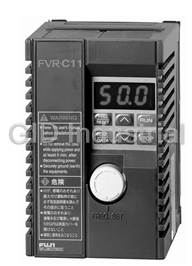


What they say about us
FANTASTIC RESOURCE
One of our top priorities is maintaining our business with precision, and we are constantly looking for affiliates that can help us achieve our goal. With the aid of GID Industrial, our obsolete product management has never been more efficient. They have been a great resource to our company, and have quickly become a go-to supplier on our list!
Bucher Emhart Glass
EXCELLENT SERVICE
With our strict fundamentals and high expectations, we were surprised when we came across GID Industrial and their competitive pricing. When we approached them with our issue, they were incredibly confident in being able to provide us with a seamless solution at the best price for us. GID Industrial quickly understood our needs and provided us with excellent service, as well as fully tested product to ensure what we received would be the right fit for our company.
Fuji
HARD TO FIND A BETTER PROVIDER
Our company provides services to aid in the manufacture of technological products, such as semiconductors and flat panel displays, and often searching for distributors of obsolete product we require can waste time and money. Finding GID Industrial proved to be a great asset to our company, with cost effective solutions and superior knowledge on all of their materials, it’d be hard to find a better provider of obsolete or hard to find products.
Applied Materials
CONSISTENTLY DELIVERS QUALITY SOLUTIONS
Over the years, the equipment used in our company becomes discontinued, but they’re still of great use to us and our customers. Once these products are no longer available through the manufacturer, finding a reliable, quick supplier is a necessity, and luckily for us, GID Industrial has provided the most trustworthy, quality solutions to our obsolete component needs.
Nidec Vamco
TERRIFIC RESOURCE
This company has been a terrific help to us (I work for Trican Well Service) in sourcing the Micron Ram Memory we needed for our Siemens computers. Great service! And great pricing! I know when the product is shipping and when it will arrive, all the way through the ordering process.
Trican Well Service
GO TO SOURCE
When I can't find an obsolete part, I first call GID and they'll come up with my parts every time. Great customer service and follow up as well. Scott emails me from time to time to touch base and see if we're having trouble finding something.....which is often with our 25 yr old equipment.
ConAgra Foods