

 Manufacturers
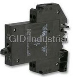
ETA-USA 2210-T210-K0M1-H121.5A
Description
ETA-USA 2210-T210-K0M1-H121.5A Circuit Breaker. Therm/Mag | 1A | 250V AC/65V DC
Part Number
2210-T210-K0M1-H121.5A
Price
Request Quote
Manufacturer
ETA-USA
Lead Time
Request Quote
Category
PRODUCTS - 2
Datasheet

Extracted Text
Thermal-Magnetic Circuit Breaker 2210-T2.. Description One, two and three pole thermal-magnetic circuit breakers with trip-free mechanism and toggle actuation (S-type TM CBE to EN 60934/IEC 934). Featuring a combi-foot design for both symmetric and asymmetric rail mounting. Available with auxiliary contact (1 x N/O or 1 x N/C) for status signalling. Two and three pole models are internally linked to ensure that both/all poles trip in the event of an overload on one pole, even if the actuator is held in the ON position. This CBE can be supplied in current ratings up to 32 A with a choice of characteristic curves. All screw terminals are recessed for safety. Approved to CBE standard EN 60934 (IEC 60934). Typical applications 2210-T2.. Process control equipment, robotics, machine tool control, 1-pole 3-pole 2 communications systems, instrumentation. Ordering information Technical data Type No. For further details please see chapter: Technical Information 2210 single and multipole thermal-magnetic circuit breaker Voltage rating AC 250 V; 3 AC 433 V (50/60 Hz); DC 65 V Mounting (UL: AC 277/480 V; DC 65 V) T rail mounting Current rating range 0.1...32 A for curves M1, T1, T2 Actuator design 0.1...16 A for curves F1, F2, M3 2 toggle Number of poles Auxiliary circuit 1 A, AC 240 V / DC 65 V 1 single pole protected Typical life 2 2-pole protected 3 AC 433 V; AC 250 V: 0.1...25 A 3 3-pole protected 10,000 operations at 1 x I , inductive N 5 2-pole, protected on one pole only DC 65 V: 0.1...32 A Accessories 10,000 operations at 1 x I , inductive N 0 without accessories 3 AC 433 V; AC 250 V: 32 A Terminal design (main contacts) 10,000 operations at 1 x I , resistive N K0 screw terminals Ambient temperature -30...+60 °C (-22...+140 °F) T 60 Characteristic curve F1 fast acting: therm.1.01-1.4xI ; magn.2-4xI DC (DC only) Insulation co-ordination rated impulse pollution N N F2 fast acting: therm.1.01-1.4xI ; (IEC 60664 and 60664 A) withstand voltage degree N magn.3,5-6,5xI AC/4,5-8,5xI DC 2.5 kV 2 N N M1 standard delay: therm. 1.01-1.4xI ; reinforced insulation in operating area N magn. 6-12xI AC, 7.8-15.6xI DC N N Dielectric strength T1 delayed: therm. 1.01-1.4 I ; magn. 10-20xI AC N N (IEC 60664 and 60664A) test voltage T2 thermal only, 1.01-1.4xI operating area AC 3,000 V N M3 standard delay, low resistance: therm. 1.4-1.8xI ; main/aux. circuit AC 3,000 V N magn. 6-12xI AC, 7.8-15.6xI DC pole/pole AC 1,500 V N N Auxiliary contact design Insulation resistance > 100 MΩ (DC 500 V) H without intermediate position Interrupting capacity I 0.1...5 A 400 A; 6...32 A 800 A; cn Auxiliary contacts curve T2 : 0.1...32 A 15 x I N 0 without auxiliary contacts curve M3: 0.1...2 A AC 200A /DC 400A 1 with auxiliary contacts Interrupting capacity 2 auxiliary contacts on pole 1 only (UL 1077) I 0.1...16 A 20...32 A (multipole devices) N 1- + 2-pole AC 277 V /5,000 A AC 277 V /2,000 A 3 auxiliary contacts on pole 1 and 3 3-pole 3 AC 480 V /5,000 A 3 AC 480 V /2,000 A (3-pole devices) 1- + 2-pole DC 65 V /2,000 A DC 65 V / 2,000 A Auxiliary contact function (see diagrams) 2 1 N/O contact Degree of protection operating area IP30 3 1 N/C contact (IEC 60529/DIN 40050) terminal area IP20 Auxiliary contact - terminal design Vibration curve F1: 1 screw terminals 3 g (57-500 Hz), ±0.23 mm (10-57 Hz) Current ratings curves M1, M3, T1, T2: 0.1...32 A 5 g (57-500 Hz), ±0.38 mm (10-57 Hz) to IEC 60068-2-6, test Fc 2210 - T 2 1 0 - K0 M1- H 1 2 1 - 10 A ordering example 10 frequency cycles/axis Shock curve F1: 25 g (11 ms), directions 1, 2, 3, 4, 5 10 g (11 ms), direction 6 curves M1, M3, T1, T2: 25 g (11 ms), directions 1, 2, 3, 4, 5 20 g (11 ms), direction 6 Approvals to IEC 60068-2-27, test Ea Corrosion 96 hours at 5 % salt mist Authority Voltage ratings Current ratings to IEC 60068-2-11, test Ka VDE (EN 60934) 3 AC 433 V; AC 250 V; DC 65 V 0.1...32 A Humidity 240 hours at 95 % RH UL, CSA 3 AC 480 V; AC 277 V; to IEC 60068-2-3, test Ca AC 277/480 V; DC 65 V 0.1...32 A Mass approx. 60 g per pole 06/07(070706) www.e-t-a.com 2 - 23 12A 12A 12A M1 M1 M1 Thermal-Magnetic Circuit Breaker 2210-T2.. Standard current ratings and typical internal resistance values Dimensions Current Internal resistance (Ω) 37.5 rating F1 F2 M1 T1 M3 T2 1.48 (A) fast acting fast acting standard delayed standard delay thermal 30.5 delay low resistance 1.20 for DC only for AC + DC for AC + DC nur für AC for AC + DC for AC + DC slot fitting labels from 45 25 toggles linked Phoenix 0.1 162 162 92 81 42 77 1.77 .984 for multipole Weidmüller 0.2 39.3 39.3 26.1 24.2 11.7 23 20 18 devices Wieland .787 .709 0.3 17.5 17.5 11.6 10.4 5.6 10.2 OFF ON 0.4 9.2 9.2 6,6 6.0 2.9 5.7 0.5 6.8 6.8 4,1 3.9 1.75 3,7 0.6 4.2 4.2 3 2.7 1.42 2.6 11.5 0.8 2.8 2.8 1.65 1.53 0.75 1.39 .453 9-12 .354-.472 1 1.6 1.6 1,10 0.98 0.5 0.9 1.5 0.78 0.78 0.47 0.42 0.22 0.36 2 2 0.42 0.42 0.28 0.24 0.136 0.19 Si Si 12-14 1 2 2.5 0.26 0,26 0.183 0.17 0.083 0.141 .472-.551 3 0.18 0.18 0.124 0.12 0.057 0.091 4 0.12 0.12 0.077 0.073 0.041 0.051 5 0.092 0.092 0.063 0.055 0.032 0.040 12.5 12.5 6 0.054 0.054 0.045 0.039 0.021 0.027 .492 .492 43.5 40 8 0.025 0.025 ≤ 0.02 ≤ 0.02 ≤ 0.02 ≤ 0.02 1.71 1.57 10 0.022 0.02 ≤ 0.02 ≤ 0.02 ≤ 0.02 ≤ 0.02 12 ≤ 0.02 ≤ 0.02 ≤ 0.02 ≤ 0.02 ≤ 0.02 ≤ 0.02 G-profile symmetric rail main contact terminal 16 ≤ 0.02 ≤ 0.02 ≤ 0.02 ≤ 0.02 ≤ 0.02 ≤ 0.02 2 EN 50035-G32 EN 50022-35x7.5 max. 6 mm (AWG 10) EN 50022-35x15/1.5 (rigid conductor) 20 - - ≤ 0.02 ≤ 0.02 - ≤ 0.02 tightening torque 0.5 Nm 25 - - ≤ 0.02 ≤ 0.02 - ≤ 0.02 Si-terminal M3 32 - - ≤ 0.02 ≤ 0.02 - ≤ 0.02 2 max. 1.5 mm (AWG 16) (rigid conductor) tightening torque 0.5 Nm Internal connection diagrams unit III unit II ...-H131-... unit I OFF position ON position line (Si) N/C contact line (Si) 0I 1 11 0I 1 11 Installation drawing 12 12 (Si) (Si) > I > I operating area (reinforced insulation) 2 2 ...-H121-... line (Si) N/O contact line (Si) 0I 1 13 0I 1 13 14 14 (Si) (Si) > > I I Si Si 2 2 1 2 Shock directions mounting area 56 1 2 3 4 mm This is a metric design and millimeter dimensions take precedence ( ) inch 2 - 24 www.e-t-a.com 06/07(070706) 12 .472 5.5 11.5 .217 .453 5.5 7.5 44 .217 .295 1.73 78.5 12.5 15 3.09 .492 .591 88.5 3.48 Thermal-Magnetic Circuit Breaker 2210-T2.. Accessories Typical time/current characteristics Connector bus links -K10 -F1 -F1 0.1 … 16 A 0.1 … 16 A DC only 2 X210 589 01/2.5 mm , (AWG 14) (black) up to 20 A max. load 10000 2 X210 589 02/1.5 mm , (AWG 16) (brown) up to 13 A max. load ø2.5 1000 50 pin lugs to .099 DIN 46230 tinned copper 100 10 1 Bus bar for 1-pole units (17-way), up to 70 A max. load 0.1 2 X221 498 01 16 x 12.5 = 200 0.01 16 x .492 = 7.87 12.5 .492 2.5 1.3 0.001 12 46810 20 40 6080100 .098 .051 … times rated current 1) -F2 0.1 … 7.5 A AC/ DC IEC 664 500 V/70 A (40 °C) CE 10000 ® E-T-A GERMANY 207 3.5 1000 8.15 .138 100 Bus bar for 2-pole units (2 x 10-way), up to 120 A max. load X221 497 01 10 9 x 25 = 225 9 x .984 = 7.87 25 1 .984 12.5 12.5 2.5 1.3 .492 .492 .098 .051 0.1 L1 L2 L1 L2 L1 L2 L1 L2 L1 L2 L1 L2 L1 L2 L1 L2 L1 L2 ® IEC 664 500 V/70 A (40°C) CE E-T-A GERMANY 0.01 250 6.5 9.84 .138 0.001 40 6080100 12 46810 20 … times rated current Bus bar for 2-pole units (2 x 4-way), up to 120 A max. load X222 002 01 1) -F2 8 …16 A AC/ DC 3 x 25 = 75 10000 3 x .984 = 2.95 25 .984 1000 2.5 1.3 12.5 .492 .098 .051 100 L1 L2 L1 L2 L1 L2 L1 L2 IEC 664 500 V/120 A (40°C) CE 10 ® E-T-A GERMANY 104 7 1 4.09 .276 Supply terminal for bus bar (up to 70 A max. load) 0.1 X221 496 01 0.01 0.001 12 46810 20 40 6080100 … times rated current +60 °C +23 °C -30 °C 4.6 +140 °F +73.4 °F -22 °F M5 .181 1) Magnetic tripping currents are increased by 30% on DC supplies. 2 conductor size max. 10 mm (AWG 8) single or stranded conductor 13 14.5 .512 .571 17 .669 mm This is a metric design and millimeter dimensions take precedence ( ) inch 06/07(070706) www.e-t-a.com 2 - 25 22 .866 9.7 11.3 .382 .445 ~70 ~2.76 2.5 1.3 .098 .051 14 .551 14 5.2 14 .551 .205 .551 29 1.14 29 29 1.14 1.14 Trip time in seconds Trip time in seconds Trip time in seconds Thermal-Magnetic Circuit Breaker 2210-T2.. Typical time/current characteristics The time/current characteristic curve depends on the ambient temperature Multi pole devices: all poles symmetrically loaded. With single pole prevailing. In order to eliminate nuisance tripping, please multiply the circuit overload, thermal tripping will be at max. 1.7 x I with curves F1, F2, M1 N breaker current ratings by the derating factor shown below. See also section 9 and T2, and at max. 2.2 x I with curve M3. N – Technical information. 1) Magnetic tripping currents are increased by 30% on DC supplies. Ambient temperature °F -22 -4 +14 +32 +73.4 +86 +104 +122 +140 °C -30 -20 -10 0 +23 +30 +40 +50 +60 Derating factor 0.76 0.79 0.83 0.88 1 1.04 1.11 1.19 1.29 1) 1) -M1 0.1 6 A AC/DC -M1 8 32 A AC/DC -T1 0.1 6 A AC only 10000 10000 10000 1000 1000 1000 100 100 100 2 10 10 10 1 1 1 0.1 0.1 0.1 0.01 0.01 0.01 0.001 0.001 0.001 12 46810 20 406080100 12 46810 20 406080100 12 46810 20 406080100 times rated current times rated current times rated current 1) 1) -T1 8 32 A AC only -M3 0.1 5 A AC/DC -M3 6 16 A AC/DC 10000 10000 10000 1000 1000 1000 100 100 100 10 10 10 1 1 1 0.1 0.1 0.1 0.01 0.01 0.01 0.001 0.001 0.001 12 46810 20 406080100 12 46810 20 406080100 12 46810 20 406080100 times rated current times rated current times rated current -T2 0.1 6 A AC/DC -T2 8 32 A AC/DC 10000 10000 1000 1000 100 100 10 10 1 1 0.1 0.1 0.01 0.01 0.001 0.001 12 46810 20 406080100 12 46810 20 406080100 times rated current times rated current +60 ¡C +23 ¡C -30 ¡C +140 ¡F +73.4 ¡F -22 ¡F All dimensions without tolerances are for reference only. In the interest of improved design, performance and cost effectiveness the right to make changes in these specifications without notice is reserved.Product markings may not be exactly as the ordering codes. Errors and omissions excepted. 2 - 26 www.e-t-a.com 06/07(070706) Trip time in seconds Trip time in seconds Trip time in seconds Trip time in seconds Trip time in seconds Trip time in seconds Trip time in seconds Trip time in seconds
Frequently asked questions
What makes Elite.Parts unique?

What kind of warranty will the 2210-T210-K0M1-H121.5A have?
Which carriers does Elite.Parts work with?
Will Elite.Parts sell to me even though I live outside the USA?
I have a preferred payment method. Will Elite.Parts accept it?


What they say about us
FANTASTIC RESOURCE
One of our top priorities is maintaining our business with precision, and we are constantly looking for affiliates that can help us achieve our goal. With the aid of GID Industrial, our obsolete product management has never been more efficient. They have been a great resource to our company, and have quickly become a go-to supplier on our list!
Bucher Emhart Glass
EXCELLENT SERVICE
With our strict fundamentals and high expectations, we were surprised when we came across GID Industrial and their competitive pricing. When we approached them with our issue, they were incredibly confident in being able to provide us with a seamless solution at the best price for us. GID Industrial quickly understood our needs and provided us with excellent service, as well as fully tested product to ensure what we received would be the right fit for our company.
Fuji
HARD TO FIND A BETTER PROVIDER
Our company provides services to aid in the manufacture of technological products, such as semiconductors and flat panel displays, and often searching for distributors of obsolete product we require can waste time and money. Finding GID Industrial proved to be a great asset to our company, with cost effective solutions and superior knowledge on all of their materials, it’d be hard to find a better provider of obsolete or hard to find products.
Applied Materials
CONSISTENTLY DELIVERS QUALITY SOLUTIONS
Over the years, the equipment used in our company becomes discontinued, but they’re still of great use to us and our customers. Once these products are no longer available through the manufacturer, finding a reliable, quick supplier is a necessity, and luckily for us, GID Industrial has provided the most trustworthy, quality solutions to our obsolete component needs.
Nidec Vamco
TERRIFIC RESOURCE
This company has been a terrific help to us (I work for Trican Well Service) in sourcing the Micron Ram Memory we needed for our Siemens computers. Great service! And great pricing! I know when the product is shipping and when it will arrive, all the way through the ordering process.
Trican Well Service
GO TO SOURCE
When I can't find an obsolete part, I first call GID and they'll come up with my parts every time. Great customer service and follow up as well. Scott emails me from time to time to touch base and see if we're having trouble finding something.....which is often with our 25 yr old equipment.
ConAgra Foods